Article

Evaluation of the Corrosion Resistance of Phosphate Coatings Deposited on the Surface of the Carbon Steel Used for Carabiners Manufacturing

by
Diana-Petronela Burduhos-Nergis
1,
Petrica Vizureanu
1,*,
Andrei Victor Sandu
1,2,3,* and
Costica Bejinariu
1,*
1
Faculty of Materials Science and Engineering, “Gheorghe Asachi” Technical University of Iași, Dimitrie Mangeron street, 67, 700050 Iași, Romania
2
Romanian Inventors Forum, Sf. P. Movila 3, 700089 Iasi, Romania
3
National Institute for Research and Development in Environmental Protection, 294 Splaiul Independentei Blvd, 060031 Bucharest, Romania
*
Authors to whom correspondence should be addressed.
Appl. Sci. 2020, 10(8), 2753; https://doi.org/10.3390/app10082753
Submission received: 18 March 2020 / Revised: 11 April 2020 / Accepted: 13 April 2020 / Published: 16 April 2020
(This article belongs to the Special Issue Obtaining, Characterization and Applications of Advanced Materials)

Abstract

:
This study aims to evaluate the corrosion resistance of carbon steel, used for carabiners manufacturing, coated with three different types of phosphate layer. The phosphate layers have been obtained by phosphate conversion coating with three different types of phosphate solutions: zinc-based solution, zinc-iron-based phosphate solution, and manganese-based phosphate solution. Additionally, the test was performed on zinc phosphate samples impregnated with molybdenum bisulfate-based oil and zinc phosphate samples further coated with a layer of elastomer-based paint. Considering the areas where the carabiners are used (civil engineering, navigation, oil industry, rescue operations, etc.), the corrosive environments studied are rainwater, Black Sea water, and fire extinguishing solution. The structure of the deposited layers was studied by scanning electron microscopy, while the interface structure between the alloy and corrosive environment was analyzed by electrochemical impedance spectroscopy. According to this study, the corrosion resistance of zinc-based phosphate coated samples and zinc/iron-based phosphate coated samples is higher than that of the studied carbon steel samples, despite the corrosion environment. Also, the most aggressive corrosion environment was the fire extinguishing solution.

1. Introduction

At the beginning of the 20th century, for safety reasons during climbing, the first safety rings were invented, previously in 1910, Hans Fiechtl invented and manufactured the python [1]. The geographical extension of mountaineering was an important factor in the modernization of height protection. In this regard, the python becomes a mandatory accessory even though it was difficult to use, however, this problem has been solved when carabiners were invented [2].
Carabiners are metal rings, with a locking element that always opens inwards, used to connect the components of the fall arrest safety system [3]. Over the years, carabiners have undergone a series of design, form, and manufacturing materials changes [4,5]. Currently, there are many types of carabiners, which are used in areas such as the oil industry, speleology, civil construction, arboriculture, etc. The most used materials from which the carabiners are made are aluminum and steel. Aluminum carabiners are used in places where weight is important (e.g., mountain climbing), while steel carabiners are used in places where mechanical or refractory properties are the priority (e.g., civil construction or in fire rescue/evacuation operations) [3,6].
According to previous studies [3,7,8,9,10,11], there are multiple factors that must be considered during designing the process of a carabiner. According to the EN 362: 2004 standard, prior and after each use, the body of the carabiner should be visually checked by the user. If during the inspection, the user notices pitting corrosion, it is recommended to withdraw the carabiner from use. Also, the carabiner should be withdrawn from use if the user notices deformations, cuts or cracks, which may occur after hitting the carabiner with other bodies. Moreover, if the carabiner has been dropped from a high height but visually does not show a crack, it must also be removed from use. Therefore, in the case of carabiners, new coatings must be developed that should provide increased corrosion resistance in multiple environments, but also, these coatings must be suitable for lubricant impregnation or further coatings.
The phosphate conversion coating is a process of depositing a layer of insoluble phosphates on the metal surface [12]. This method is encouraged by economical aspects and by its easy-to-use and feasibility characteristics. However, the structural, chemical, and mechanical characteristics of the deposited layer are highly dependent on the phosphate solution composition [13]. Therefore, the choice of the most suitable phosphate solution for carabiners coating must be done through experimental studies. Taking into account the corrosion mechanism of structure and characteristics (porosity, crystallinity, etc.) of the phosphate layers, the corrosion resistance of the deposited layers could be evaluated using electrochemical impedance spectroscopy (EIS).
The phosphate conversion coating is a process of depositing a layer of insoluble phosphates on the metal surface [12]. This method is encouraged by economical aspects and by its easy-to-use and feasibility characteristics. However, the structural, chemical, and mechanical characteristics of the deposited layer are highly dependent on the phosphate solution composition [13].
When a metal or alloy with a freshly sanded surface or coated with various films is introduced into an electrolytic environment, a series of interactions occur that modify the metal/electrolyte interface. The main interaction is the electrochemical corrosion reaction of the metal or alloy components, a process that is mainly an oxidation reaction [14]. Due to this, on the metal surface, a positive ions layer accumulates and in front of it, from the solution, a layer of negative ions is oriented, thus forming the electric double layer (EDL) [15]. This layer works as a protective barrier in the further development of the corrosion reaction and influences the reaction rate, thus representing the kinetic reaction factor. The reaction products can be soluble and pass through the corrosion medium or insoluble and can pass into the solution, and thus be deposited on the alloy surface without being too adherent or they can form a compact film that is strongly adherent to the metal. If the metal is coated with a porous layer, the insoluble reaction products can partially or completely clog the pores [16].
Another effect of the interaction between the alloy and the corrosion environment could be the partial degradation of the coating layer. Consequently, by absorbing the liquid, ions or by adsorption molecules from the corrosion environment, the pores can grow and the layer can detach from the metal surface, changing its thickness [17].

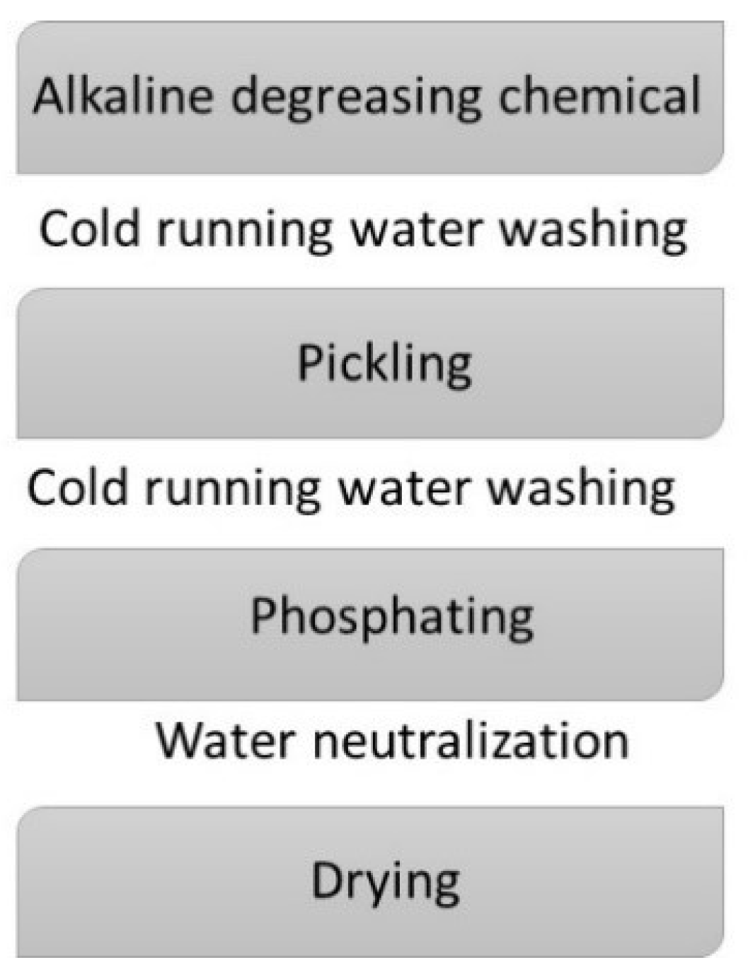
2. Materials and Methods

According to the chemical composition (Table 1), determined as presented in [13], the base material used in this study is C45 carbon steel. Before the phosphating process, the carbon steel round bar, used for carabiners manufacturing, was cut into cylindrical shape samples with dimensions of ø 10 mm × 3 mm.
The phosphating process used in this study consist of multiple stages, according to the process flow diagram presented in Figure 1.
The multistage phosphating process starts with the alkaline chemical degreasing, which aims to remove the grease and oils used in the obtaining of C45 round bars. The following stage, pickling, removes the impurities and the oxides from the surface of the sample. After the alkaline chemical degreasing, as well as after the pickling of the samples, they are rinsed in cold water in order to remove any residual solution from their surface. After pickling, the active surface is coated with a phosphate layer to maintain the samples in the phosphate bath for a specific period of time. The phosphating stage is followed by water neutralization in order to clean the phosphate salts from the surface of the sample. Finally, the samples are dried (drying) in a stove for 4 h at 120 °C [12,18]. The process parameters (time and temperature) for all the phosphate coatings, used in this study, are as follows: alkaline chemical degreasing for 10 min at 85 ±1 °C; pickling for 20 min at room temperature (22 ±2 °C); phosphating for 30 min at 90 ±1 °C.
Although the phosphate coating by the immersion process takes longer, compared to the sputtering process, due to the uniform coverage of the material surface and taking into account the size, shape, and manufacturing process of the carabiner, this method was considered as the most suitable for depositing the phosphate layer [3,18].
In order to obtain a phosphate layer that will improve the corrosion resistance of carbon steel, as well as, a layer that can be used as a substrate for further coatings, three phosphating solutions were used, the first is a zinc-based solution (I-Zn), the second solution contains zinc and iron (II-Zn/Fe) and the third is a manganese-based solution (III-Mn) [18]. As can be seen in Figure 2, the morphology of the phosphate layer depends on the phosphate bath chemical solution. Because the zinc phosphate coatings ensure increased durability of the painted parts in corrosive environments [11], the use of the I-Zn phosphate layer was chosen as the basic layer for the paint deposition. Both the molybdenum bisulfate-based oil and the paint used in this study were purchased from the market. The elastomers-based paint is a product used for car paint, which protects against external factors, such as impact with stones or other objects, due to the elasticity it possesses [19,20,21].
The EIS analyses were performed on C45 steel, on C45 phosphate steel with three types of phosphate solutions with different compositions, as well as, on C45 phosphate steel samples with a zinc-based solution and immersed in MoS2 oil or painted samples. The following notations were used to simplify writing:
  • C45—C45 steel sample;
  • I-Zn—The C45 steel phosphate in zinc-based solution sample;
  • II-Zn/Fe—The C45 steel phosphate in zinc/iron-based solution sample;
  • III-Mn—The C45 steel phosphate in manganese-based solution sample;
  • OPS—The C45 steel phosphate in zinc-based solution and immersed in MoS2 oil sample;
  • PPS—The C45 steel phosphate in zinc-based solution and painted sample.
The liquids used in this work as corrosion environments were noted with:
  • RW—Rainwater, pH = 6.5;
  • BSW—Black Sea water, pH = 6.15;
  • FES—Fire extinguishing solution, pH = 6.41.
The pH value of these solutions was determined with a pH meter RADELKIS OP-264/1 type.
The morphology of the deposited layers has been analyzed using a scanning electron microscope (SEM, TESCAN VEGA 3 LMH, Czech Republic).
EIS measurements were performed with the PGZ 301 potentiostat (Radiometer Analytical SAS, Villeurbanne Cedex, France), and the acquisition of the experimental data was performed with the VoltaMaster 4 software. The experimental data were processed with the ZSimpWin software, in which the spectra are evaluated by the fitting procedure developed by Boukamp, i.e., using the smallest squares method. In order to analyze the data acquired with the VoltaMaster 4 software, the files were converted using the EIS file converter software (Radiometer Analytical S.A.).
For the electrochemical impedance spectroscopy determinations, a corrosion cell with three electrodes was used. The glass cell, C145/170 type (Radiometer, France), allows the circulation of the corrosion environment liquid. The samples (discs of 10 mm in diameter and 3 mm in thickness) are fixed on the working electrode by means of Teflon washers, thus covering a small area of the sample. In the case of the studied samples, the area (S) of the exposed surface to the corrosion environment was of S = 0.503 cm2. As an auxiliary electrode, a platinum disk electrode with the exposed surface of 0.8 cm2 was used, and as the reference electrode, a saturated calomel electrode was used. All the potentials were measured in relation to this electrode, but for simplification of writing, this wasn’t specified in all the tables and discussion. Also, the corrosion resistance evaluation has been performed in normal environmental conditions, i.e., corrosion solution was naturally aerated and the working temperature was 25 °C.
The working sequence for all measurements was: working potential = open circuit potential, frequency range 104 ÷ 25·10−2 Hz, sinusoidal potential amplitude = 10 mV. Measurements at frequencies higher than 104 Hz were avoided because a series of preliminary tests [13,20] indicated the presence of a negative loop in the very high-frequency region in the Nyquist diagram. This behavior is probably due to the very high resistance of the reference electrode [22].
Electrochemical impedance data are represented in the form of two types of diagrams; the Nyquist diagram in which in the abscissa is represented by the real part of the impedance, and the ordinate, the imaginary part of the measured impedance (-ImZ vs. ReZ) and the Bode diagram in which the impedance module is represented by the logarithm frequency and phase angle as a function of frequency logarithm (lZl vs. frequency).
The equivalent circuits that are the most equivalent circuits by means of Boukamp encoding used in the ZSimpWin software, according to the procedure are presented in [23].

3. Results and Discussion

3.1. Structural Analysis

As can be seen in Figure 2, the morphology of the phosphate layer depends on the phosphate bath chemical solution. The microstructural analysis of the I-Zn (Figure 2a) and II-Zn/Fe (Figure 2b) samples shows multiple zinc phosphate tetrahydrate crystals of different sizes that are interwoven throughout the steel surface. Also, the layer shows some pores (black dots) and intercrystalline zones, which are related to the phosphate layer specific porosity [24]. The phosphate crystals present on the steel surface are fine, compact, and have the form of flowers or plates, this form being specific to the hopeite. The main difference between I-Zn and II-Zn/Fe samples is the size of the phosphate crystal, which is much smaller in the case of the II-Zn/Fe samples.
The manganese phosphate layer (Figure 2c) has a different morphology compared to the zinc phosphate and zinc/iron phosphate layers. Crystals corresponding to manganese phosphate are smaller compared to those of zinc phosphate. Due to the nickel and iron presence in the solution, the size of the phosphate crystals decreases, consequently, large surfaces being uniformly coated as a result of the overlapping of the crystals at the microscopic level. The layer morphology can be attributed to the accelerating effect of the galvanic couples formed between the iron and nickel ions, which act as crystallization centers in the formation process, increasing their number exponentially and resulting in a layer with a high number of small crystals.

3.2. Corrosion Resistance Evaluation

The processing of the experimental data for all the 18 systems of alloy/corrosion environments allowed the identification of 7 equivalent circuits with which the surface properties can be analyzed after one hour in the liquid environment. When choosing these circuits, it was taken into account that the value of the factor χ2 and the relative measurement error of the impedance εz to be as small as possible.

3.2.1. The Equivalent Circuit R(QR(LR))

The electrical equivalent circuit presented in Figure 3a describes the best experimental data for the C45/seawater system. The Nyquist diagram (Figure 3b) for this sample, after one hour of immersion in seawater, shows a depressed semicircle in the high-frequency region and an inductive loop in the low-frequency region. This inductive loop can be attributed to adsorption of ions, neutral molecules, or even of some particles (insoluble corrosion products) from the solution, but it may also indicate the existence of intermediate reactions related to the adsorption of aggressive chlorine ions, which produce instability of the electrode surface [25,26,27,28].
However, a better adjustment of the data was obtained by replacing the capacity of the double layer with a constant phase element, respectively constant phase element (CPE), which indicates the non-ideal behavior of the capacity of the double-electric layer (changing the capacity with frequency). The equivalent circuit R(QR(LR)) consists of a resistor (Rs) in series with a parallel combination of a CPE, a resistor (Rct), and a resistor-inductance series combination (RL, L). The values of the parameters that best satisfy the parameter data are presented in Table 2.
The χ2 parameter values and the Z percentage errors of the elements of this circuit show a satisfactory adjustment of the data with this circuit.
As can be seen in Table 2, the charge-transfer resistance (Rct) has a relatively low value indicating a high corrosion rate. Also, by corrosion, the surface of the sample becomes rough, which makes the capacity of the electric double layer unimportant, thus it is necessary to introduce the constant phase element. The deviation of the frequency exponent (n) from the value 1 is a measure of the deviation from the ideality of the capacitor that represents the capacity of the double-electric layer. The polarization resistance, in this case, is calculated with the relation: Rp = (Rct · RL)/(Rct + RL). On the surface of the sample, no continuous layer was formed, but only insoluble ions and/or corrosion products were adsorbed. Due to this fact in the equivalent circuit, the RL-L series group was introduced in parallel with the time constant characteristic for the double layer (CPE-Rct). The circuit element RL represents the resistance due to the components adsorbed on the surface and L is an inductor (coil), which in EIS describes the inductive loops in the low-frequency region.
The Bode diagram shows the existence of a single maximum on the curve θ = f(ν) (the phase angle depending on the frequency of the applied signal), which implies the existence of a single relaxation time constant.
In Black Sea water (BSW), due to the aggressiveness of the chlorine ions, the steel, especially the iron, is rapidly attacked, yet a continuous film of corrosion reaction products isn’t formed on the surface. In this case, the reaction products (oxides or oxy-hydroxides insoluble) take the form of granules being only partially adsorbed to the surface. Consequently, a negative loop in the low-frequency region appears on the Nyquist diagram, and a solenoid and RL resistor must be introduced into the equivalent circuit. Under these conditions, the polarization resistance is Rp = 1503 Ω·cm2.

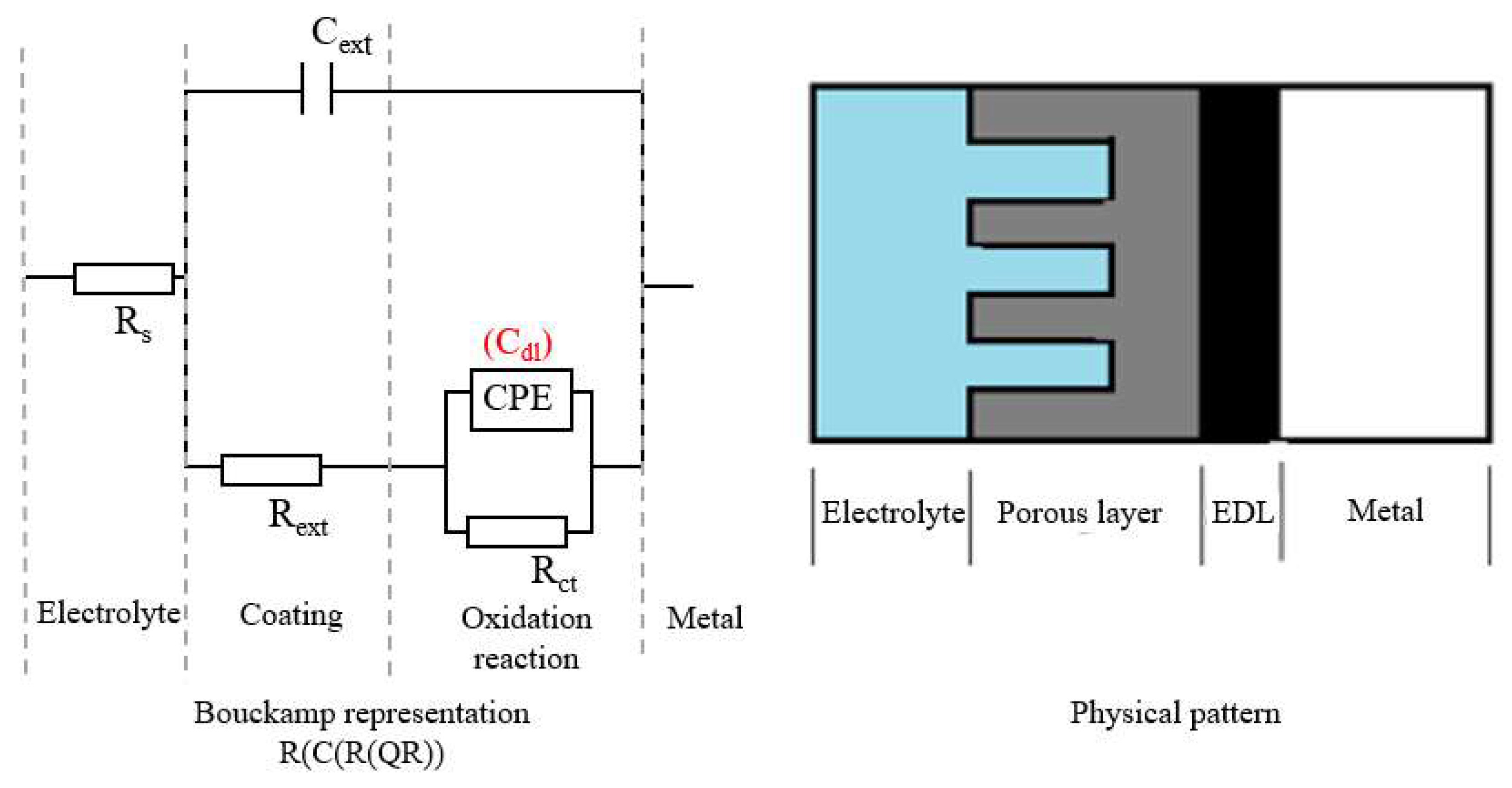
3.2.2. The Equivalent Circuit R(C(R(QR)))

The equivalent circuit shown in Figure 4 was the most suitable for fitting the data (empirical curve fitting) obtained for the C45/rainwater system, for all three phosphate samples in seawater (I-Zn/BSW, II-Zn/Fe/BSW and III-Mn/BSW) and for the oil sample/rainwater system (OPS/RW). The circuit describes a double-layer model, in which the pair (Rext, Cext) represents the properties of the coating layer, while the pair (CPE, Rct) represents the properties of the double-electric layer, which is responsible for the kinetics of the corrosion process. Rs is the uncompensated resistance of the electrolyte column between the reference electrode and the working electrode.
In the case of C45 immersed in rainwater, the surface layer is very thin and probably non-conductive, this being characterized by an extremely low electrical capacity (2.54 nF) and high electrical resistance (1014 Ω·cm2), as can be seen in Table 3.
For both C45 and the three phosphate samples, the surface layer is uniform, both in terms of composition and microstructure, so that the capacity of this layer is represented by an ideal capacitor.
In the case of the C45/rainwater system, the electric capacity of the surface layer is extremely low (2.54 pF). This is explained by the fact that although the thickness of the product layer formed in the initial moments is very small, it is impregnated with rainwater whose conductivity is low ( ε r = 81; ε = ε r ε 0 = 81 8 1 854.10 12 F/m). For the same reason, the strength of this layer is high. The resistance of the electric double layer (Rct—load transfer resistance) is also very high so that the polarization resistance here is: Rp = Rct + Rext = 4980 Ω·cm2.
For phosphate samples, the capacity is in the range of microfarads, these values are characteristic for porous layers. Because the pores are filled with the corrosion environment solution (in this case seawater) and their resistance is very low. For the I-Zn sample immersed in seawater, the charge transfer resistance is the highest; the phosphate layer deposited with the I-Zn solution provides better corrosion protection compared to the other two phosphate solutions. The frequency exponent value in this case (n = 0.51) indicates that the constant phase element that replaces the capacity of the electric double layer is, in fact, a Warburg element, which also indicates the influence of diffusion on the corrosion rate.
The load transfer resistance (Rct) decreases in the following order I-Zn> II-Zn / Fe> III-Mn, where I-Zn exhibits the best corrosion protection. The capacity of the electric double layer is represented by a non-ideal capacitor; therefore, it was necessary to introduce the constant phase element (CPE) because the deviation from ideal behavior is very high.
In the case of phosphate and impregnated oil samples immersed in rainwater, the resistance of the surface layer and especially the resistance of the electric double layer are very high, which is why the polarization resistance is in the order of tens of kΩ·cm2 (more precisely: Rp = 23, 9 kΩ·cm2). Therefore, the instantaneous corrosion rate could not be measured, and the constant phase element has the significance of a Warburg impedance.
The solution resistance in the case of the OPS/RW system is higher than in the case of the C45/RW system, although the geometry of the measuring cell is the same because the resistance of the oil film is added to the actual resistance of the solution.

3.2.3. The Equivalent Circuit R(Q(R(QR)))

The equivalent circuit shown in Figure 5 describes a two-layer physical state, identical to the one described by the circuit in Figure 4, with the difference that in these cases the electrical capacity of the surface layer is described by a non-ideal capacitor, represented by the CPE1 constant phase element.
This circuit was suitable for processing the EIS data recorded for I-Zn, II-Zn/Fe, and III-Mn after one hour of immersion in rainwater and in fire extinguishing solution. The parameter values of the circuit elements for these systems are presented in Table 4.
As well as for the other alloys immersed in rainwater, the surface layer of phosphate samples consists of an extremely thin film saturated with rainwater. This protecting layer has a very low electrical capacity, in the range of microamperes, and very high resistance, in the range of kΩ/cm2. Given that the frequency exponent of the expression of the constant phase element CPE1 is very close to the unit, it is, in fact, an almost ideal capacitor.
For the same systems, the charge transfer resistance is also high; therefore, the electric double layer acts as a barricade in the evolution of the corrosion reaction. Moreover, the electrical capacity of this layer is a non-ideal capacitor, probably due to the irregularity of the phosphating layer and its porosity.
The polarization resistance for the phosphate samples decreases in the following order:
I-Zn (44.0 kΩ⋅cm2)> II-Zn/Fe (3.85 kΩ⋅cm2)> III-Mn (2.86 kΩ⋅cm2)
This indicates that the sample phosphate in solution I-Zn has the best corrosion resistance when exposed to rainwater, while the sample phosphate in solution III-Mn shows the lowest corrosive resistance.
When exposed to fire extinguisher solution, the polarization resistances of the phosphate samples are much lower, and vary in the following order:
II-Zn/Fe (1.272 kΩ⋅cm2)> I-Zn (0.441 kΩ⋅cm2)> III-Mn (0.133 kΩ⋅cm2).
In this highly corrosive environment, the fire extinguishing solution, the most corroded material is also the sample phosphate in the III-Mn solution. Moreover, as can be seen, the best sample, in terms of corrosion resistance is II-Zn in this case. This order inversion that appears in the obtained results can be explained by the absorption and/or adsorption of some compounds from the solution in the pores of the phosphate layers, because the dimensions of the pores differ from one sample to another, depending on the phosphating conditions.

3.2.4. The Equivalent Circuit R(C(R(Q(RW))))

The experimental data for the C45/fire extinguishing solution system were processed with the equivalent circuit shown in Figure 6. This circuit is characteristic of a corrosive metal coated with a porous non-conducting layer in which the corrosion process is carried out under a mixed kinetic and diffusion control. In this case, the coating layer is formed by adsorption of the solution components on the surface of the freshly polished alloy. The deposited layer is compact enough to act as a barrier for the electrons transfer, which is taking place by diffusion.
In this equivalent circuit, Rs is the resistance of the solution, Rext and Cext are the resistance and the electric capacity of the coating layer, Rct and CPE are the resistance and the constant phase element that takes place from the capacity of the electric double layer (these control the reaction rate from the kinetic point of view), and W is the characteristic constant from the diffusion impedance expression, this is the parameter that controls the reaction rate through the influence of the diffusion of oxidizing and reducing species to and from the metal. The experimental values of the parameter for the elements of this circuit are presented in Table 5.
In the fire extinguishing solution, even if the surface of the alloy is freshly polished, because the solution or one of its components adhere to the surface of the metal, from the initial moments it is necessary to use a double-layer model. Also, the diffusion must be taken into account because on the metal surface a very thin layer is formed. Due to the fact that the film is porous and therefore its resistance is very low, it does not influence the resistance of the solution or the resistance of the charge transfer. Moreover, this surface layer is uniform so that its capacity is represented by an ideal capacitor. The resistance of the electric double layer is relatively high, much higher than the value of the polarization resistance evaluated from the linear polarization curve, in the present case. However, the EIS method underestimates the conductive properties of the electric double layer.

3.2.5. The Equivalent Circuit R(Q(R(Q(RW))))

The circuit shown in Figure 7 was used to describe the superficial properties of the OPS samples immersed in water from the Black Sea and fire extinguishing solution for one hour (the OPS/RW and OPS/FES systems). As in the case of the circuit described prior, this system consists of a double-layer structure in which the reaction rate is controlled by kinetics and diffusion. The main difference, compared to the previous system, is that the capacity of the surface layer is represented by a non-ideal capacitor emphasized by the constant phase element CPE1. The experimental values obtained for the parameters of this circuit are presented in Table 6.
The polarization resistance value (RP = Rext + Rct) for the OPS/BSW system (8.65 kΩ cm2) is double than the value for the OPS/fire extinguishing solution system (4.51 kΩ·cm2). Also, the effect of the diffusion on the decrease of the corrosion rate favors the OPS/RW system (the diffusion impedance ZW is inversely proportional to W). The sum of these components (kinetic and diffusion) leads to a significant reduction in the corrosion rate, which is incomparably lower than that obtained for the C45 sample and the phosphate samples in the same solutions (2 to 5 times in the case of seawater and 2 to 6 times in the case of the fire extinguishing solution); furthermore, the instantaneous diffusion rate is 114 µm/year in seawater, while in fire extinguishing solution the rate is of 243 µm/year.

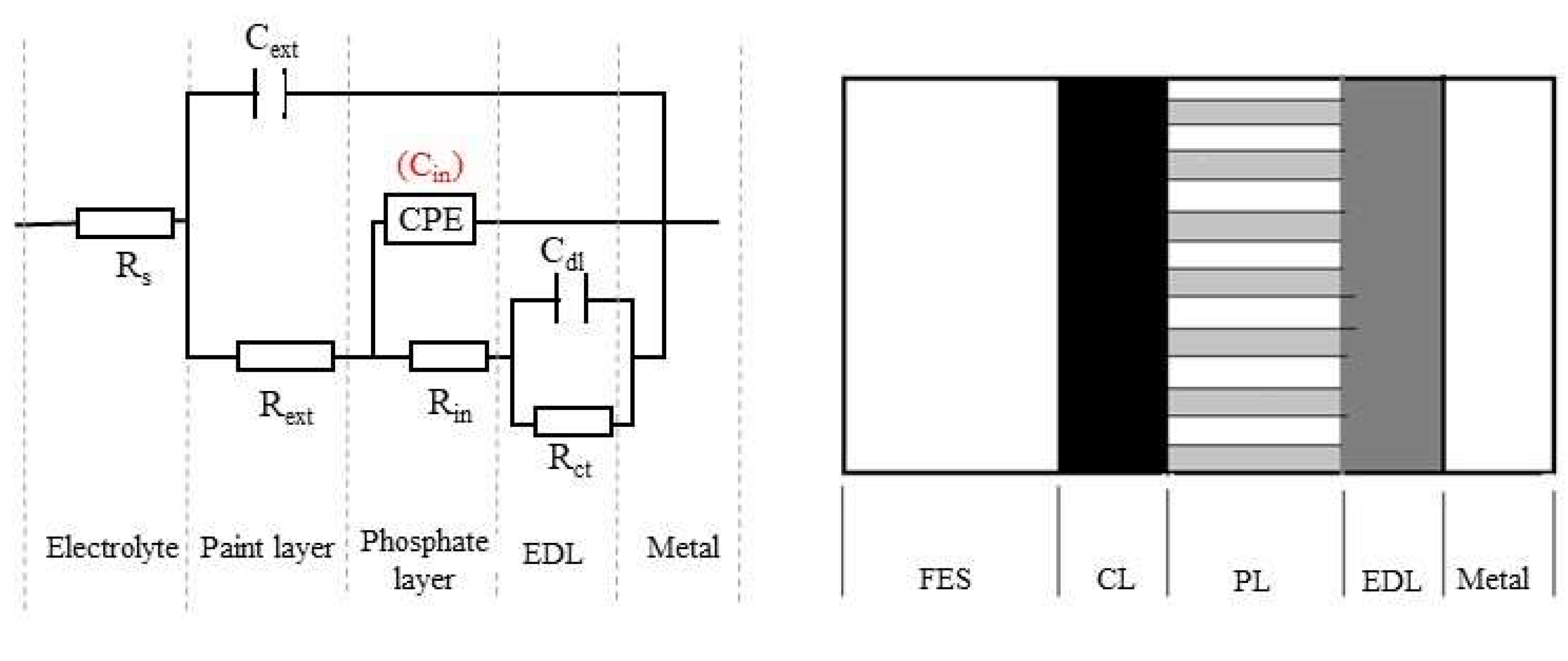
3.2.6. The Equivalent Circuit R(C(R(Q(R(CR)))))

The equivalent circuit shown in Figure 8 describes a three-layer physical state, which is suitable for the C45 phosphate and painted steel samples immersed in all three corrosion environments. In this case, the surface layer is the paint film (CL) that has a very low electrical conductivity, very thin, while having high resistance and very high electrical capacity in rainwater. However, in seawater, the paint layer exhibits very low resistance, and it seems that it is rapidly deteriorating. The experimental values obtained for the parameters of this circuit are presented in Table 7.
The resistance of the porous phosphate layer (PL) is lower for PPS than in the case of the I-Zn sample. This change can be due to the fact that the pores are no longer clogged with compounds from the fire extinguishing solution or with reaction products, because in this case, the reaction rate is very low and the quantity of reaction products is very small. Also, the electrical capacity of this layer is represented by non-ideal capacitors as a consequence of the high surface roughness.
In rainwater, the charge transfer resistance (Rct) is very high and it can be correlated with the resistance of the other layers, the polarization resistance is very high (Rp = Rext + Rin + Rct = 10.4 kΩ·cm2). In the case of immersion in seawater, Rct has the lowest value and thus the polarization resistance is also very low (RP = 1.22 kΩ·cm2), therefore, the paint layer does not provide satisfactory protection in seawater.

4. Conclusions

In order to evaluate the corrosion resistance of surfaces with high electrochemical impedance, the method of electrochemical impedance spectroscopy (EIS) is suitable, especially to study the degradation of metals covered with organic layers (paints). Moreover, in this study all the experimental data for the six alloys immersed in three corrosion environments could be processed with only three equivalent cell types.
According to the EIS experimental data:
-
the C45 samples exhibit a double layer structure with high polarization resistance and low corrosion rate when exposed to rainwater (RW). When exposed to Black Sea water (BSW), due to the aggressiveness of the chlorine ions, the steel, especially the iron, is rapidly attacked, consequently, the polarization resistance is 3.3 times lower and the corrosion rate is higher. In the fire extinguishing solution (FES), the equivalent circuit used is characteristic to a corrosive metal coated with a porous non-conducting layer in which the corrosion process is carried out under a mixed, kinetic and diffusion control. The estimated corrosion rate of the C45 samples exposed to FES is close to the value which corresponds to BSW;
-
the phosphate samples (I-ZN, II-Zn/Fe and III-Mn) exhibit a double-layer structure when exposed to RW, where the I-ZN sample (based on Zn3 (PO4)2) exhibits the best corrosion resistance - more than 10 times higher than that presented by the II-ZN/Fe and III-Mn samples. The sample with the lowest corrosion resistance is the III-Mn sample which was coated with an Mn3 (PO4)2 + Fe + Ni-based solution. The corrosion rates of phosphate samples are higher when exposed to BSW, compared to RW, also, the I-Zn phosphate sample provides the best corrosion protection, while the III-Mn phosphate sample the lowest. In FES, the II-Zn/Fe sample appears as the sample with the highest corrosion resistance, while the I-Zn sample is the second.
-
the phosphate and oil immersed samples (OPS) show a very low corrosion rate in OPS/RW system. In the case of OPS/RW and OPS/FES systems, the circuit used describes a double-layer physical system with kinetic and diffusion mixed corrosion rate control. The capacities (expressed by the constant phase elements CPE1 and CPE2), the resistances (Rext and Rct) and the Warburg constant (W) obtained for OPS samples in both corrosion environments are in the same range. Given the very low values of the constant W, the diffusion impedance (ZW) is very high. The sum of kinetic (Rct + Rext) and diffusional (ZW) components leads to a very high polarization resistance and a significant reduction in corrosion rate, moreover, the instantaneous diffusion rate is 114 µm/year in seawater, while in FES it is of 243 µm/year.
-
the phosphate and rubber painted samples (PPS) were analyzed with a circuit that describes a three-layer physical state, with kinetic control of the corrosion rate. This type of sample shows high corrosion resistance in RW and FES, yet, in BSW the rubber layer is rapidly dissolved.
The aggressiveness of the corrosion environments is controlled by their composition (aggressive ions, inhibitors of neutral molecules, etc.) and by their electrical conductivity. The highest mean electrical conductivity value is presented by the fire extinguishing solution (Rs 4.71 ± 0.14 Ω·cm2), while for the seawater the value is eight times higher (Rs = 38.55 ± 1.45 Ω·cm2).

Author Contributions

Writing original draft and investigation, D.-P.B.-N.; data curation and validation, A.V.S.; validation and writing—reviewing and editing, P.V.; validation and writing, project administration and scientific supervision, C.B. All authors have read and agreed to the published version of the manuscript.

Funding

This research received no external funding.

Conflicts of Interest

The authors declare no conflicts of interest.

References

  1. Samet, M. The Climbing Dictionary: Mountaineering Slang, Terms, Neologisms & Lingo: An Illustrated Reference to More Than 650 Words; Mountaineers Books: Seattle, WA, USA, 2011; ISBN 9781594855023. [Google Scholar]
  2. Bright, C.M. A History of Rock Climbing Gear Technology and Standards; ScholarWorks@UARK: Fayetteville, NC, USA, 2014. [Google Scholar]
  3. Burduhos-Nergis, D.P.; Baciu, C.; Vizureanu, P.; Lohan, N.M.; Bejinariu, C. Materials types and selection for carabiners manufacturing: A review. IOP Conf. Ser. Mater. Sci. Eng. 2019, 572, 012027. [Google Scholar] [CrossRef]
  4. Aliha, M.R.M.; Bahmani, A.; Akhondi, S. Fracture and fatigue analysis for a cracked carabiner using 3D finite element simulations. Strength Mater. 2015, 47, 890–902. [Google Scholar] [CrossRef]
  5. Blair, K.B.; Custer, D.R.; Graham, J.M.; Okal, M.H. Analysis of fatigue failure in D-shaped karabiners. Sports Eng. 2005, 8, 107–113. [Google Scholar] [CrossRef]
  6. Burduhos Nergiş, D.P.; Nejneru, C.; Achiţei, D.C.; Cimpoieşu, N.; Bejinariu, C. Structural Analysis of Carabiners Materials Used at Personal Protective Equipments. IOP Conf. Ser. Mater. Sci. Eng. 2018, 374, 012040. [Google Scholar] [CrossRef]
  7. Zafren, K.; Durrer, B.; Herry, J.P.; Brugger, H. Lightning injuries: Prevention and on-site treatment in mountains and remote areas: Official guidelines of the International Commission for Mountain Emergency Medicine and the Medical Commission of the International Mountaineering and Climbing Federation (ICAR and UIAA MEDCOM). Resuscitation 2005, 65, 369–372. [Google Scholar]
  8. Scott, V. Design of a Composite Carabiner for Rock Climbing; Final Report; Allen Institute for AI: London, UK, 2008. [Google Scholar]
  9. Smith, R.A. The development of equipment to reduce risk in rock climbing. Sports Eng. 1998, 1, 27–39. [Google Scholar] [CrossRef] [Green Version]
  10. Harutyunyan, D.; Milton, G.W.; Dick, T.J.; Boyer, J. On ideal dynamic climbing ropes. Proc. Inst. Mech. Eng. Part P J. Sports Eng. Technol. 2017, 231, 136–143. [Google Scholar] [CrossRef] [Green Version]
  11. Nergis, D.P.B.; Cimpoesu, N.; Vizureanu, P.; Baciu, C.; Bejinariu, C. Tribological characterization of phosphate conversion coating and rubber paint coating deposited on carbon steel carabiners surfaces. Mater. Today Proc. 2019, 19, 969–978. [Google Scholar] [CrossRef]
  12. Bejinariu, C.; Burduhos-Nergiș, D.P.; Cimpoeșu, N.; Bernevig-Sava, M.A.; Toma Ștefan, L.; Darabont, D.C.; Baciu, C. Study on the anticorrosive phosphated steel carabiners used at personal protective. Calitatea 2019, 20, 71. [Google Scholar]
  13. Burduhos-Nergiș, D.P.; Nejneru, C.; Cimpoeșu, R.; Cazac, A.M.; Baciu, C.; Darabont, D.C.; Bejinariu, C. Analysis of chemically deposited phosphate layer on the carabiners steel surface used at personal protective equipments. Qual. Access Success 2019, 20, 77–82. [Google Scholar]
  14. Etteyeb, N.; Sanchez, M.; Dhouibi, L.; Alonso, C.; Andrade, C.; Triki, E. Corrosion protection of steel reinforcement by a pretreatment in phosphate solutions: Assessment of passivity by electrochemical techniques. Corros. Eng. Sci. Technol. 2006, 41, 336–341. [Google Scholar] [CrossRef]
  15. Jegdić, B.V.; Bajat, J.B.; Popić, J.P.; Stevanović, S.I.; Mišković-Stanković, V.B. The EIS investigation of powder polyester coatings on phosphated low carbon steel: The effect of NaNO2 in the phosphating bath. Corros. Sci. 2011, 53, 2872–2880. [Google Scholar] [CrossRef]
  16. Manna, M. Characterisation of phosphate coatings obtained using nitric acid free phosphate solution on three steel substrates: An option to simulate TMT rebars surfaces. Surf. Coat. Technol. 2009, 203, 1913–1918. [Google Scholar] [CrossRef]
  17. Dhouibi, L.; Triki, E.; Salta, M.; Rodrigues, P.; Raharinaivo, A. Studies on corrosion inhibition of steel reinforcement by phosphate and nitrite. Mater. Struct. 2003, 36, 530–540. [Google Scholar] [CrossRef]
  18. Burduhos-Nergis, D.-P.; Bejinariu, C.; Toma, S.-L.; Tugui, A.-C.; Baciu, E.-R. Carbon steel carabiners improvements for use in potentially explosive atmospheres. MATEC Web Conf. 2020, 305, 00015. [Google Scholar] [CrossRef]
  19. Burduhos-Nergis, D.-P.; Sandu, A.-V.; Burduhos-Nergis, D.-D.; Darabont, D.-C.; Comaneci, R.-I.; Bejinariu, C. Shock Resistance Improvement of Carbon Steel Carabiners Used at PPE. MATEC Web Conf. 2019, 290, 12004. [Google Scholar] [CrossRef]
  20. Burduhos Nergis, D.P.; Nejneru, C.; Burduhos Nergis, D.D.; Savin, C.; Sandu, A.V.; Toma, S.L.; Bejinariu, C. The galvanic corrosion behavior of phosphated carbon steel used at carabiners manufacturing. Revista de Chimie 2019, 70, 215–219. [Google Scholar] [CrossRef]
  21. Nejneru, C.; Perju, M.C.; Nergis, D.D.B.; Sandu, A.V.; Bejinariu, C. Galvanic Corrosion Behaviour of Phosphate Nodular Cast Iron in Different Types of Residual Waters and Couplings. Revista de Chimie 2019, 70, 3597–3602. [Google Scholar] [CrossRef]
  22. Cottis, R.; Turgoose, S. Electrochemical Impedance and Noise; Syrett, B.C., Ed.; NACE International: Houston, TX, USA, 1999; ISBN 157-590-0939. [Google Scholar]
  23. Huang, J.; Li, Z.; Liaw, B.Y.; Zhang, J. Graphical analysis of electrochemical impedance spectroscopy data in Bode and Nyquist representations. J. Power Sources 2016, 309, 82–98. [Google Scholar] [CrossRef]
  24. Teixeira, C.H.S.B.; Alvarenga, E.A.; Vasconcelos, W.L.; Lins, V.F.C. Effect of porosity of phosphate coating on corrosion resistance of galvanized and phosphated steels Part I: Measurement of porosity of phosphate. Mater. Corros. 2011, 62, 771–777. [Google Scholar] [CrossRef]
  25. Itagaki, M.; Taya, A.; Watanabe, K.; Noda, K. Deviations of capacitive and inductive loops in the electrochemical impedance of a dissolving iron electrode. Anal. Sci. 2002, 18, 641–644. [Google Scholar] [CrossRef] [PubMed] [Green Version]
  26. Cao, C.; Zhang, J. Introduction of Electrochemical Impedance Spectroscopy; Science Press of China: Beijing, China, 2002; ISBN 7-03-009854-4. [Google Scholar]
  27. Chen, M.; Du, C.Y.; Yin, G.P.; Shi, P.F.; Zhao, T.S. Numerical analysis of the electrochemical impedance spectra of the cathode of direct methanol fuel cells. Int. J. Hydrogen Energy 2009, 34, 1522–1530. [Google Scholar] [CrossRef]
  28. Nakayama, S.; Kaji, T.; Notoya, T.; Osakai, T. Mechanistic study of the reduction of copper oxides in alkaline solutions by electrochemical impedance spectroscopy. Electrochim. Acta 2008, 53, 3493–3499. [Google Scholar] [CrossRef]
Figure 1. Phosphating process flow diagram.
Applsci 10 02753 g001
Figure 2. Morphology of the phosphate layers: (a) I-Zn; (b) II-Zn/Fe; (c) III-Mn.
Applsci 10 02753 g002
Figure 3. Equivalent circuit (a), Nyquist diagram (b) and Bode diagrams (c) for the C45/BSW system after one hour of immersion.
Applsci 10 02753 g003
Figure 4. The equivalent circuit for the corrosion of a coated metal. EDL, electric double layer.
Applsci 10 02753 g004
Figure 5. The equivalent circuit R(Q(R(QR))) for all phosphate samples immersed in rainwater and fire extinguishing solution.
Applsci 10 02753 g005
Figure 6. The equivalent circuit R(C(R(Q(RW)))) for a corrosive alloy under mixed kinetic and diffusion control.
Applsci 10 02753 g006
Figure 7. The equivalent circuit for a corrosive alloy with kinetic and diffusion evolution of reaction rate II.
Applsci 10 02753 g007
Figure 8. The equivalent circuit R(C(R(Q(R(CR))))) for EIS data fitting for the PPS samples immersed in RW, BSW and fire extinguishing solution.
Applsci 10 02753 g008
Table 1. Chemical composition of C45 steel.
ElementCSiMnPCuCrFe
wt, %0.450.220.980.020.150.17balance
Table 2. Equivalent circuit parameters for C45 after one hour of immersion in Black Sea water.
Rs,
Ω cm2
CPERct,
Ω cm2
RL,
Ω cm2
L,
H cm2
1032εz *
Q,
Ssn/cm2
n
39.63.418 × 10−40.78058810074965.926.34
εEC**, %1.225.61.593.955.42.87--
* εz—inductance measurement error; ** εEC—relative error.
Table 3. Equivalent circuit parameters for the systems analyzed with the circuit presented in Figure 4.
SystemRs,
Ω·cm2
Cext,
µF/cm2
Rext,
Ω·cm2
CPERct,
Ω·cm2
103χ2εZ
Q
S·sn/cm2
n
C45/RW13862.54 × 10−310141.00 × 10−40.6535960.9323.05
I-Zn/BSW36.30.10630.826.20 × 10−50.5119825.777.59
II-Zn/Fe/BSW40.42.87011.042.51 × 10−40.618830.6942.44
III-Mn/BSW37.94.462.765.31 × 10−20.734630.1091.02
OPS/RW19692.06 × 10−613931.48 × 10−50.492.19 × 1041.894.68
Table 4. Parameter values of equivalent circuit elements R(Q(R(QR))) for phosphate C45 samples, after one hour of immersion in rainwater and fire extinguishing solution respectively.
SystemRs,
Ω cm2
CPE 1Rext
Ω cm2
CPE 2Rct
Ω cm2
103χ2εZ
Q1
Ssn/cm2
n1Q2
Ssn/cm2
n2
I-Zn/RW29137.78 × 10−100.9048949.53 × 10−60.523.91 × 1040.251.57
II-Zn/Fe/RW23281.63 × 10−90.9519871.58 × 10−40.6818580.211.44
III-Mn/RW21592.45 × 10−90.9515071.51 × 10−30.7213575.527.5
I-Zn/FES4.591.14 × 10−30.791157.22 × 10−30.643260.882.97
II-Zn/Fe/FES4.643.80 × 10−40.632832.03 × 10−30.539892.264.75
III-Mn/FES4.963.47 × 10−20.801303.62 × 10−20.782.970.211.46
Table 5. The values of the equivalent circuit elements for C45 immersed for one hour in fire extinguishing solution.
SystemRs,
Ω cm2
Cext
µF/cm2
Rext
Ω cm2
CPERct
Ω cm2
W
S s½/c
103χ2εZ
Q
S.sn/cm2
n
C45/FES4.641.716.421.43 × 10−30.6515440.2770.552.3
Table 6. The values of the equivalent circuit elements for OPS samples immersed in seawater and fire extinguishing solution.
SystemRs,
Ω cm2
CPE 1Rext,
Ω cm2
CPE 2Rct
Ω cm2
W
Ss½/cm2
103χ2εZ
Q1
Ssn/cm2
n1Q2
Ssn/cm2
n2
OPS/RW28.833.16 × 10−50.5447535.44 × 10−50.7338935.00 × 10−47.88.8
OPS/FES6.696.95 × 10−50.712713.63 × 10−50.7042468.30 × 10−48.89.4
Table 7. The values of the equivalent circuit for PPS samples immersed in RW, BSW and fire extinguishing solution.
SystemRs
Ω·cm2
Cext
F/cm2
Rext
Ω·cm2
CPERin
Ω·cm2
Cdl
F/cm2
Rct
Ω·cm2
103χ2εZ
Q
S·sn/cm2
n
OFV/RW14990.73 × 10−1247093.83 × 10−40.59521161.752080.862.95
OFV/BSW107.10.17519.126.51 × 10−40.6316.520.411790.582.41
OFV/FES16.852.81191.80 × 10−40.7657617516040.472.17

