Article

Fermi-Level Pinning Mechanism in MoS2 Field-Effect Transistors Developed by Thermionic Emission Theory

1
School of Materials Science and Engineering, Shanghai University, Shanghai 200444, China
2
Organic Optoelectronics Engineering Research Center of Fujian’s Universities, College of Electronics and Information Science, Fujian Jiangxia University, Fuzhou 350108, China
3
College of Science, Shanghai Institute of Technology, Shanghai 201418, China
*
Authors to whom correspondence should be addressed.
Appl. Sci. 2020, 10(8), 2754; https://doi.org/10.3390/app10082754
Submission received: 28 February 2020 / Revised: 11 April 2020 / Accepted: 13 April 2020 / Published: 16 April 2020
(This article belongs to the Section Electrical, Electronics and Communications Engineering)

Abstract

:
Molybdenum disulfide (MoS2) field-effect transistors (FETs) with four different metallic electrodes (Au,Ag,Al,Cu) of drain-source were fabricated by mechanical exfoliation and vacuum evaporation methods. The mobilities of the devices were (Au) 21.01, (Ag) 23.15, (Al) 5.35 and (Cu) 40.52 cm2/Vs, respectively. Unpredictably, the on-state currents of four devices were of the same order of magnitude with no obvious difference. For clarifying this phenomenon, we calculated the Schottky barrier height (SBH) of the four metal–semiconductor contacts by thermionic emission theory and confirmed the existence of Fermi-level pinning (FLP). We suppose the FLP may be caused by surface states of the semiconductor produced from crystal defects.

1. Introduction

Two-dimensional (2D) materials have attracted great attention with the birth of graphene in 2004 [1]. 2D materials are planar materials with atomic thickness [2]. They have excellent electrical properties, outstanding flexibility and good transparency [3,4]. These new physical properties can meet the needs of different applications such as electronics, photo electricity, energy storage and conversion [5]. In recent years, the transition metal dichalcogenides (TMDs), as an important part of 2D materials, have attracted great interest due to their various electrical properties including metal [6], semi-conducting [7], superconducting [8], charge density wave [9] and so on.
Molybdenum disulfide (MoS2) is a typical material of TMDs. It is one of the most promising candidates to be the semiconductor of the next generation [5]. MoS2 has a direct bandgap of 1.8 eV, which is suitable for developing field-effect transistors (FETs) with low static power consumption and high carrier mobility [10]. In the past decade, studies around MoS2-FET were focused on devices preparation [11], electrode contact [12], hysteresis phenomenon [13], heterojunction structure [14], material modification [15], and so on. However, the research on the comparison of different typical electrode materials in MoS2-FET are relatively rare.
In this paper, we prepared MoS2 materials through a classical mechanical exfoliation method [1], fabricated the devices with different metallic electrodes, and characterized them subsequently. We found that the on-state currents of four devices were of the same order of magnitude with no obvious difference. In order to clarify the internal mechanism, we calculated the Schottky barrier height (SBH) of the four metal–semiconductor contacts by thermionic emission theory and discovered that there may exist Fermi-level pinning (FLP) between the contacts in four devices [16].

2. Experiment

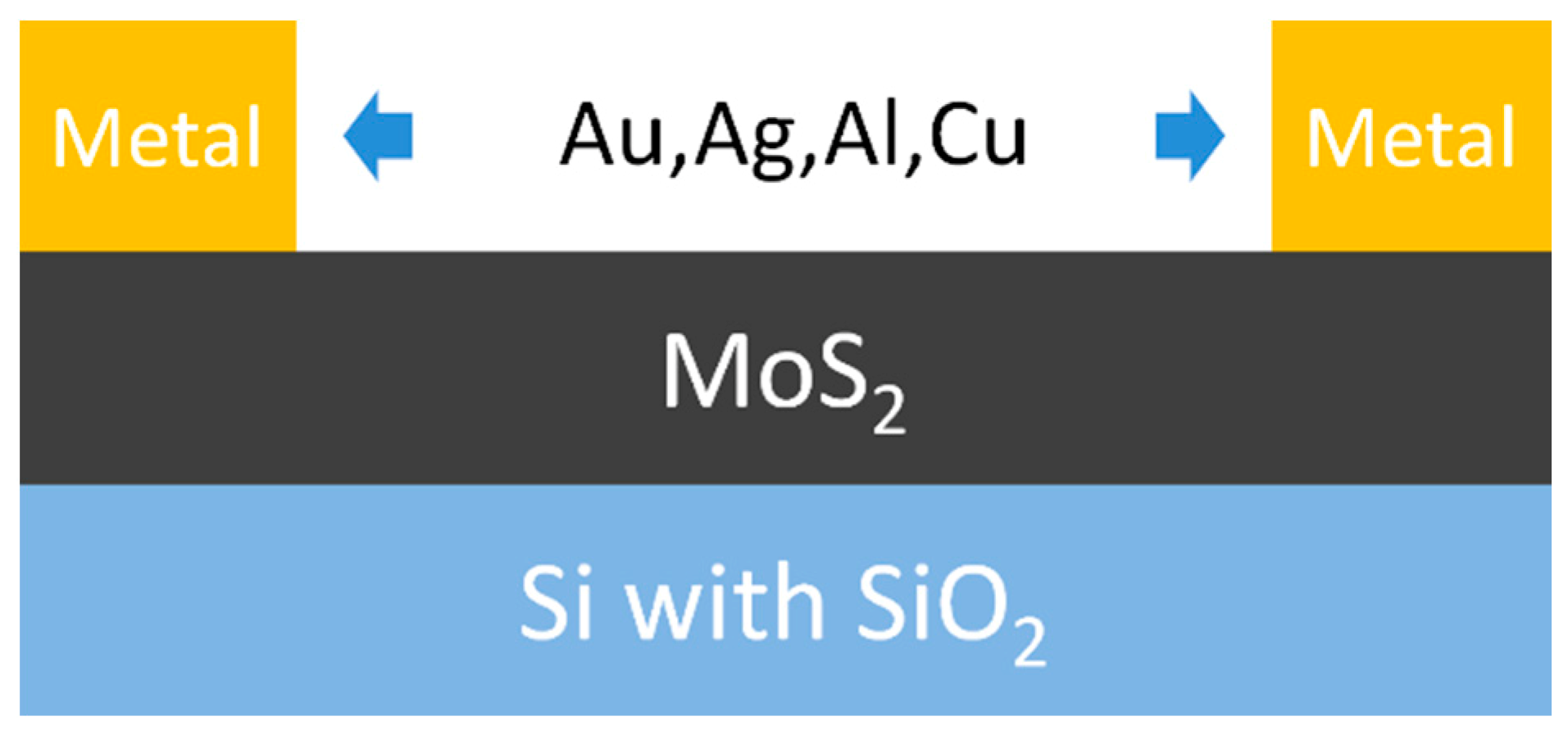
MoS2 materials were purchased from a 2D semiconductors company. We exfoliated MoS2 flakes with 3M Scotch tapes pasting for several times. Then, a substrate of n-type silicon wafer with 300 nm-thick silicon oxide was prepared. It was cleaned with acetone (for 20 min) and isopropanol (for 20 min) by ultrasonic. Then, the MoS2 flake was transferred to the substrate by 3M Scotch tapes. Next, the substrate covered with MoS2 was sent to the vacuum chamber. The first electrode material of Au was evaporated in the chamber through a shadow mask with 50 μm length channel. The fabrication process and structure of FET devices are shown in Figure 1 and Figure 2, respectively. Three other materials of Ag, Al and Cu were used as electrodes in the other three devices fabricated by the process mentioned above. Finally, four FET devices were prepared. The micro-images of the devices were obtained by optical microscope (LEICA DM 2700M), as shown in Figure 3a–d. The electrical properties of the devices were characterized by semiconductor characterization analyzer (Keithley 4200).

3. Results and Discussion

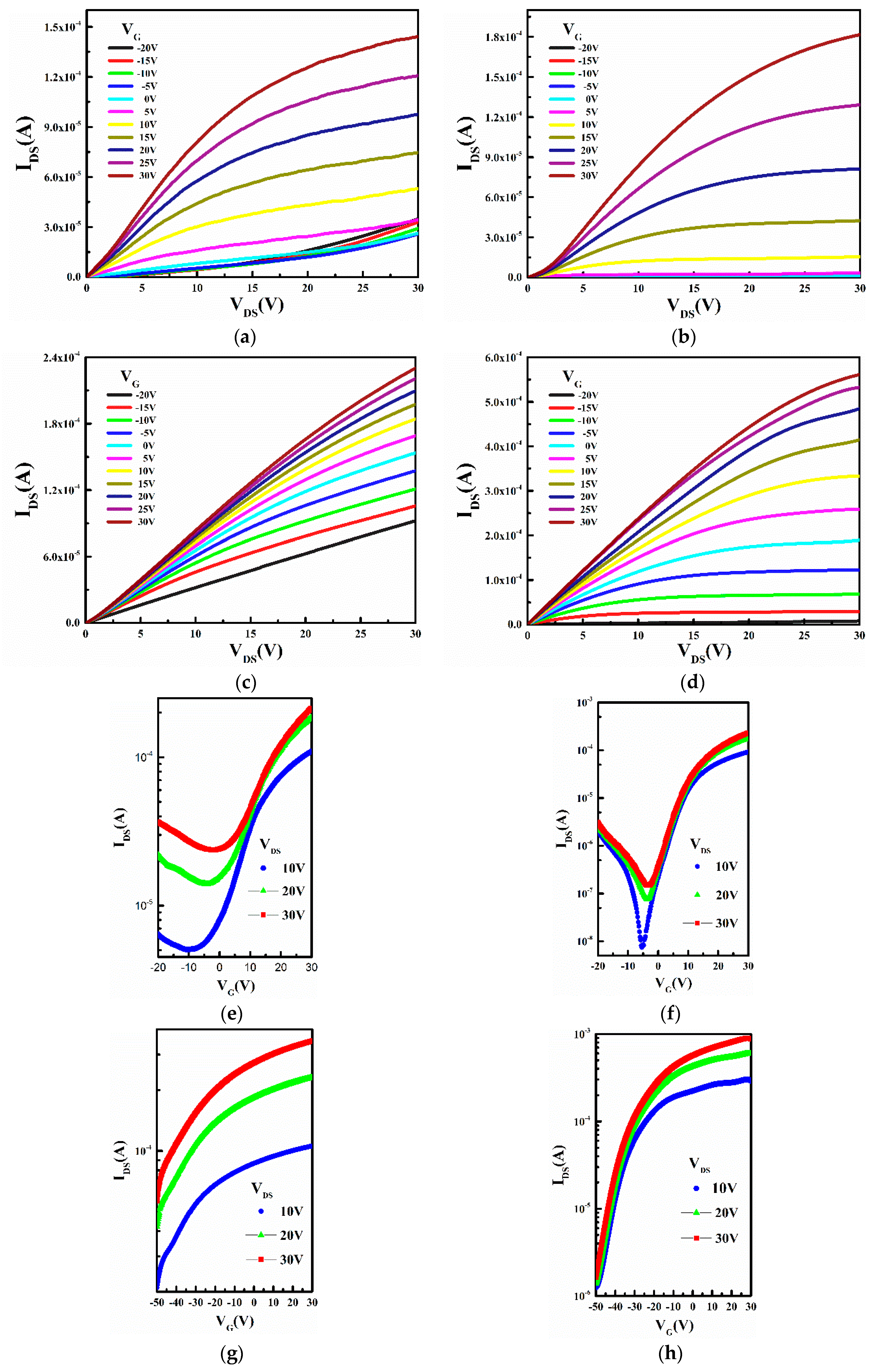
The output and transfer curves of the devices with four types of metallic electrodes are shown in Figure 4. We can find that the devices are n-type depletion FETs as the current appeared in the negative coordinates in the transfer curve with the drain-source voltage of 10 V, 20 V and 30 V, as shown in Figure 4e–h. This result is consistent with previous studies. Meanwhile, we obtained the on/off ratio, threshold voltage (Vth) from the curves and calculated the carrier mobility [15] through the Equation (1). Where W denotes the channel width, L denotes channel length, Ci stands for the capacitance per unit area of silicon oxide.
μ c a r r i e r = W L C i V D S I D S ( V GS V t h )
The characteristics of the devices are as shown in Table 1. We can find that the device with silver electrode has the relative ideal performance with a carrier mobility of 23.15 cm2/Vs, the largest on/off ratio of 1.23 × 10⁴ and the lowest threshold voltage of 2.21 V. This phenomenon may attributed to the fact that the work function of silver (4.26 eV) is close to the conduction band of molybdenum disulfide.
The property of metal–semiconductor contact is essential to modern electronics and optoelectronics [17]. According to the thermionic emission theory, the mean free path of the majority of carriers (electrons) in n-type semiconductor-metal contact is much larger than the Schottky barrier width, so the collision of electrons in the barrier region can be neglected. The influence of the barrier shape is not prominent, and the Schottky barrier height (SBH) plays a decisive role here. SBH represents the energy required for a single charge carrier to transfer between semiconductor and metal. It fundamentally determines the efficiency of charge transfer and directly affects device performance [18]. Meanwhile, SBH is derived from the difference of work functions between metal and semiconductor, which can lead to discrepancies in barrier height and charge injection quantity [19]. All of these factors will eventually cause an obvious disparity in on-state current, which is presented on the transfer characteristic curve. Figure 5 is the on-state current of MoS2 devices with four metallic electrodes at three types of drain-source voltage. The difference in the on-state currents in the transfer curve is less than 0.63 orders of magnitude that cannot fit with the gaps in the work functions of the four metals.
As mentioned above, electrons in semiconductors can enter metals through barriers as long as they have enough energy to cross barriers. Similarly, electrons in metals can also enter semiconductors. Based on the above conditions, the calculation of current can be reduced to the calculation of the number of carriers crossing the barrier, as shown in Equation (2) [16], where A is the Richardson constant (120 A/cm2·K2), T is the thermodynamic temperature (300 K), K0 is the Boltzmann constant (1.380 × 10⁻²³ J/K), VDS is the drain-source voltage (10 V), qΦSB is SBH, q is the electron charge (1.602 × 10⁻¹⁹ C), and J is the current density between semiconductor and metal. It is known that the drain-source current (IDS) is the product of the current density (J) and the average contact area S of the electrode in the device, as shown in Equation (3). We substituted it into Equation (2) to obtain Equation (4). SBHs corresponding to different gate voltages between metals and semiconductors can be calculated with the known constant and IDS in the device transfer characteristic curve at VDS = 10 V.
J = A T 2 exp ( q Φ S B k 0 T ) exp ( q V D S k 0 T )
I d s = J S
Φ S B = ln ( I D S A T 2 S ) k 0 T q + V D S
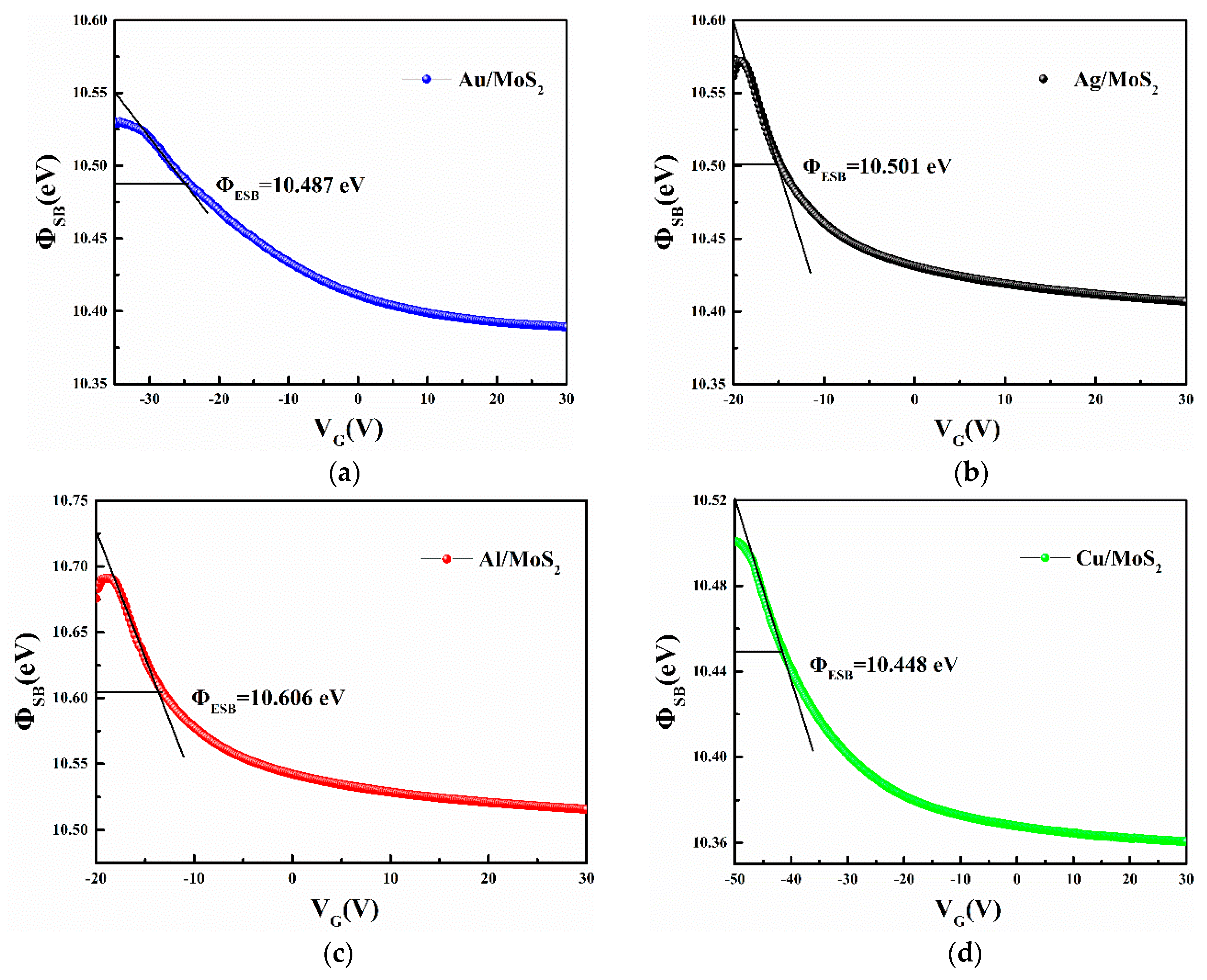
The effective barrier height (ΦESB), defined as the SBH when Vg equals to flat-band voltage (VFB), can be represented as the longitudinal coordinate value corresponding to an intersection point of the tangent of the descending position and the curve, as shown in Figure 6. It can be seen that ΦESB values of the four types of metal–semiconductor contacts ranged from 10.448 to 10.606 eV with a difference of no more than 0.16 eV. In ideal metal–semiconductor contact, SBH can be well predicted by the Schottky–Mott rule, as shown in Equations (5) and (6) [20], where ΦM is the work function of metals; XS and IS are the electron affinity and ionization potential of semiconductors; ΦSB,n and ΦSB,p are the SBH of electrons and holes, respectively. The Schottky–Mott rule shows that ΦSB is linearly related to the work function of metals, and its relationship curve has a uniform slope, as shown in Equation (7). In Equation (7), if S = 1, the metal–semiconductor system conforms to Schottky–Mott rule. However, the calculation based on the experimental data in this paper shows that there is no linear correlation between ΦSB and metal work function for S = 0.11 in the four metal material systems as shown in Figure 7a. Theoretically, the above results are due to the effect of Fermi-level pinning (FLP). Meanwhile, the results we obtained were concluded from the statistical data based on a certain number of devices that meant the experimental results have high repeatability. Moreover, we present another group of four devices with the calculated S value of 0.019 in Figure 7b. This result is in good accordance to the former group.
We suppose the main causes of FLP are the surface states of semiconductors [20,21] formed by crystal defects [20,21,22,23] such as interface reconstruction. If the surface density of states of MoS2 is very large, the metal semiconductor system will screen the effect of metal contact on the barrier. Here, the barrier height at the metal-semiconductor interface is mainly determined by the surface properties of MoS2, but not the work function of the metal. In general, due to the difference in the surface density of states, a part of the contact potential difference will fall in the semiconductor with metal–semiconductor contact, so the work function of metal may still impact on the surface barrier, but to a small extent. This is in accordance with our calculated results for the barrier heights of the four devices.
Φ S B , n = Φ M X s
Φ S B , p = I s Φ M
S = | d Φ S B d Φ M |

4. Conclusions

In this paper, the FLP mechanism was found in the MoS2-FETs by calculating the barrier height through thermionic emission theory. The FLP limits some performance of the FETs with different electrodes and may be caused by the surface states of semiconductors produced from crystal defects. Current studies will be helpful for obtaining a deep understanding of the metal–MoS2 contact mechanism and can lay a foundation for the preparation of high performance MoS2-FET devices.

Author Contributions

Perform experiment and writing: Y.Z., X.C., Y.W., X.G.; data test: S.H., J.Z., G.W., J.Q.; Super vision and review: X.W., J.W., H.Z. All authors have read and agreed to the published version of the manuscript.

Funding

This work was supported by Technology and the Natural Science Foundation of Fujian Province, China (Grant No. 2017J01733, 2018J01641, 2019J01880) and “Scientific Research Guidance Project” (Grant No. 2017H0004) of Fujian provincial department of science.

Conflicts of Interest

The authors declare no conflict of interest.

References

  1. Novoselov, K.; Geim, A.K.; Morozov, S.; Jiang, D.; Zhang, Y.; Dubonos, S.V.; Grigorieva, I.V.; Firsov, A.A. Electric Field Effect in Atomically Thin Carbon Films. Science 2004, 306, 666–669. [Google Scholar] [CrossRef] [PubMed] [Green Version]
  2. Novoselov, K.S.; Geim, A.K.; Morozov, S.V.; Colombo, L.; Gellert, P.R.; Schwab, M.G.; Kim, K. A Roadmap for Grapheme. Nature 2012, 490, 192–200. [Google Scholar] [CrossRef] [PubMed]
  3. Xu, X.; Yao, W.; Xiao, D.; Heinz, T.F. Spin and pseudospins in layered transition metal dichalcogenides. Nat. Phys. 2014, 10, 343–350. [Google Scholar] [CrossRef]
  4. Balabai, R.; Solomenko, A. Flexible 2D layered material junctions. Appl. Nanosci. 2018, 9, 1011–1016. [Google Scholar] [CrossRef]
  5. Halim, U.; Zheng, C.R.; Chen, Y.; Lin, Z.; Jiang, S.; Cheng, R.; Huang, Y.; Duan, X. A Rational Design of Cosolvent Exfoliation of Layered Materials by Directly Probing Liquid-solid Interaction. Nat. Commun. 2013, 4, 2213. [Google Scholar] [CrossRef] [PubMed]
  6. Duan, X.; Wang, C.; Pan, A.; Yu, R. ChemInform Abstract: Two-Dimensional Transition Metal Dichalcogenides as Atomically Thin Semiconductors: Opportunities and Challenges. ChemInform 2016, 47, 81–87. [Google Scholar] [CrossRef]
  7. Hong, X.; Kim, J.; Shi, S.; Zhang, Y.; Jin, C.; Sun, Y.; Tongay, S.; Wu, J.; Zhang, Y.; Wang, F. Ultrafast charge transfer in atomically thin MoS2/WS2 heterostructures. Nat. Nanotechnol. 2014, 9, 682–686. [Google Scholar] [CrossRef] [Green Version]
  8. Ugeda, M.M.; Bradley, A.J.; Zhang, Y.; Onishi, S.; Chen, Y.; Ruan, W.; Ojeda-Aristizabal, C.; Ryu, H.; Edmonds, M.T.; Tsai, H.-Z.; et al. Characterization of collective ground states in single-layer NbSe2. Nat. Phys. 2015, 12, 92–97. [Google Scholar] [CrossRef]
  9. Hoesch, M.; Cui, X.; Shimada, K.; Battaglia, C.; Fujimori, S.; Berger, H. Splitting in the Fermi surface of ZrTe3: A surface charge density wave system. Phys. Rev. B 2009, 80, 075423. [Google Scholar] [CrossRef] [Green Version]
  10. Radisavljevic, B.; Radenovic, A.; Brivio, J.; Giacometti, V.; Kis, A. Single-layer MoS2 transistors. Nat. Nanotechnol. 2011, 6, 147–150. [Google Scholar] [CrossRef]
  11. Yi, M.; Shen, Z. A review on mechanical exfoliation for the scalable production of graphene. J. Mater. Chem. A 2015, 3, 11700–11715. [Google Scholar] [CrossRef]
  12. Liu, H.; Si, M.; Deng, Y.; Neal, A.T.; Du, Y.; Najmaei, S.; Ajayan, P.M.; Lou, J.; Ye, P.D. Switching Mechanism in Single-Layer Molybdenum Disulfide Transistors: An Insight into Current Flow across Schottky Barriers. ACS Nano 2013, 8, 1031–1038. [Google Scholar] [CrossRef] [PubMed] [Green Version]
  13. Di Bartolomeo, A.; Genovese, L.; Giubileo, F.; Iemmo, L.; Luongo, G.; Foller, T.; Schleberger, M. Hysteresis in the transfer characteristics of MoS2 transistors. 2D Mater. 2017, 5, 015014. [Google Scholar] [CrossRef] [Green Version]
  14. Zhang, Y.; Ye, J.; Matsuhashi, Y.; Iwasa, Y. Ambipolar MoS2 Thin Flake Transistors. Nano Lett. 2012, 12, 1136–1140. [Google Scholar] [CrossRef] [PubMed]
  15. Das, S.; Chen, H.-Y.; Penumatcha, A.V.; Appenzeller, J. High Performance Multilayer MoS2 Transistors with Scandium Contacts. Nano Lett. 2012, 13, 100–105. [Google Scholar] [CrossRef] [PubMed]
  16. Lee, S.; Tang, A.; Aloni, S.; Wong, H.-S.P. Statistical Study on the Schottky Barrier Reduction of Tunneling Contacts to CVD Synthesized MoS2. Nano Lett. 2015, 16, 276–281. [Google Scholar] [CrossRef]
  17. Das, S.; Appenzeller, J. Where Does the Current Flow in Two-Dimensional Layered Systems? Nano Lett. 2013, 13, 3396–3402. [Google Scholar] [CrossRef]
  18. Kaushik, N.; Nipane, A.; Basheer, F.; Dubey, S.; Grover, S.; Deshmukh, M.M.; Lodha, S. Schottky barrier heights for Au and Pd contacts to MoS2. Appl. Phys. Lett. 2014, 105, 113505. [Google Scholar] [CrossRef]
  19. Guo, Y.; Liu, D.; Robertson, J. 3D Behavior of Schottky Barriers of 2D Transition-Metal Dichalcogenides. ACS Appl. Mater. Interfaces 2015, 7, 25709–25715. [Google Scholar] [CrossRef] [Green Version]
  20. Liu, Y.; Guo, J.; Zhu, E.; Liao, L.; Lee, S.-J.; Ding, M.; Shakir, I.; Gambin, V.; Huang, Y.; Duan, X. Approaching the Schottky–Mott limit in van der Waals metal–semiconductor junctions. Nature 2018, 557, 696–700. [Google Scholar] [CrossRef]
  21. Sankey, O.F.; Allen, R.E.; Dow, J.D. Si/transition-metal Schottky barriers: Fermi-level pinning by Si dangling bonds at interfacial vacancies. Solid State Commun. 1984, 49, 1–5. [Google Scholar] [CrossRef]
  22. Zan, R.; Ramasse, Q.M.; Jalil, R.; Georgiou, T.; Bangert, U.; Novoselov, K.S. Control of Radiation Damage in MoS2 by Graphene Encapsulation. ACS Nano 2013, 7, 10167–10174. [Google Scholar] [CrossRef] [PubMed] [Green Version]
  23. Zhao, B.; Shang, C.; Qi, N.; Chen, Z.; Chen, Z. Stability of defects in monolayer MoS2 and their interaction with O2 molecule: A first-principles study. Appl. Surf. Sci. 2017, 412, 385–393. [Google Scholar] [CrossRef]
Figure 1. Fabrication process of field-effect transistor (FET) devices.
Applsci 10 02754 g001
Figure 2. Molybdenum disulfide (MoS2) FET devices structure.
Applsci 10 02754 g002
Figure 3. Microscope images of FET devices with the electrode of (a) Au; (b) Ag; (c) Al; (d) Cu.
Applsci 10 02754 g003
Figure 4. Output curve of (a) Au, (b) Ag, (c) Al, (d) Cu and transfer curve of (e) Au, (f) Ag, (g) Al, (h) Cu.
Applsci 10 02754 g004
Figure 5. The comparison of the on-state current of MoS2 devices with 4 different metallic electrodes at 3 different types of drain-source voltage of (a) 10 V; (b) 20 V; (c) 30 V.
Applsci 10 02754 g005
Figure 6. Barrier heights of MoS2-FETs constructed by electrode of (a) Au; (b) Ag; (c) Al;(d) Cu.
Applsci 10 02754 g006
Figure 7. Calculated interface S values of devices comparing to Schottky–Mott rule in (a) Group 1 and (b) Group 2.
Applsci 10 02754 g007
Table 1. Characteristic data of the MoS2-FET devices (VDS = 10 V).
ElectrodeMobility (cm2/Vs)On/Off RatioThreshold Voltage(V)
Au21.012.18 × 101−3
Ag23.151.23 × 1042.21
Al5.354.14 × 100−55
Cu40.522.25 × 102−55