Article

Experimental Investigation of Stochastic Mechanical Behavior of Cement Emulsified Asphalt Mortar under Monotonic Compression

1
School of Civil Engineering, Central South University, 22 Shaoshan Road, Changsha 410075, China
2
National Engineering Laboratory for High Speed Railway Construction, 22 Shaoshan Road, Changsha 410075, China
*
Author to whom correspondence should be addressed.
Appl. Sci. 2020, 10(8), 2860; https://doi.org/10.3390/app10082860
Submission received: 14 March 2020 / Revised: 14 April 2020 / Accepted: 15 April 2020 / Published: 20 April 2020

Abstract

:
Experimental investigation on cement emulsified asphalt mortar (CA mortar) under uniaxial monotonic compression by taking into account the stochastic properties were investigated. An analytical constitutive model based on the statistic damage approach capable of mimicking the stochastic mechanical responses of CA mortar under uniaxial compression was proposed. The comparison between the experimental results and the predictions demonstrated that the proposed model was able to characterize the salient features for CA mortar under uniaxial monotonic compression. Furthermore, the compressive stochastic evolution (SE) of CA mortar tested in this work and comparative analyses among typical China Railway Track System-I (CRTS-I) type CA mortar and concrete in several aspects were examined and performed; it was revealed that the Lognormal distribution density function can well represent the damage probability density for CA mortar, and its stochastic constitutive relationship can be reflected by a media process of transition from microscale to macroscale.

1. Introduction

Cement and emulsified asphalt mortar (CA mortar) is an inorganic–organic composite material, which mainly consists of cement, emulsified asphalt, sand, and admixtures and is considered as a key material used in the construction of high-speed railway and road pavement [1,2,3,4,5,6]. In China, CA mortar is employed as the cushion layer and casted between the ballastless track slab and the concrete bed plate for providing leveling, load bearing and transmitting, vibration absorption, segregation and geometrical adjustment in CRTS (China Railway Track System) type I and II track structure [7,8].
To date, much effort has been directed towards the exploration of relevant properties for CA mortar due to its crucial role in safety and life control for railway track structures. Generally, three major categories can be identified in present research topics referring to CA mortar: (a) physical and chemical properties of fresh CA mortar [9,10,11,12,13,14,15,16,17,18,19], which mainly incorporate the properties of rheology, water absorption and expansibility, seepage, and expansibility; (b) mechanical properties of hardened CA mortar [8,20,21,22,23,24,25,26,27,28,29,30,31,32,33,34,35,36], where particular attention is chiefly paid to the issues of critical compressive strength, Young’s modulus, strain–stress relationship, strain rate effect, and temperature sensitivity; (c) investigations of the durability properties of hardened CA mortar [37,38,39,40,41,42,43,44,45,46,47], which primarily aim at the behaviors of fatigue properties, creep and stress relaxation, freezing resistance, and water erosion.
Among foregoing categories of research topics, the mechanical behavior of CA mortar is recognized as paramount. In view of CA mortar normally being under the coupling effect of varied loading frequencies and temperatures during the service condition, the mechanical properties have been usually examined incorporated with strain rate effects and temperature sensitivity. Such approaches have been applied successfully to deal with relative topics, and a variety of works can be traced [8,21,23,24,25,26,28,29,30,31,32,33,45]. In detail, several conclusions are can be drawn according to those researches: (1) the compressive strength, compressive strain, and the elastic modulus are much more sensitive than traditional Portland cement mortar and concrete to strain rate effect [28]; (2) the peak strength, discrete dynamic Young’s modulus, and specific energy absorption increase with strain rate [8,21,23,25,26,31]; (3) the compressive strength and elastic modulus increase monotonically with confining pressure [24]; (4) increasing temperature results in the decrease of mechanical properties such as resilient modulus, compressive strength, and flexural strength, the temperature sensitivity and loading rate dependence for mechanical properties with higher asphalt-to-cement content ratio (A/C) are greater than those with lower A/C [22,25,32,33,45]; (5) the storage modulus gradually decreases with increasing temperature and decreases with the increase of A/C and water content [29].
As a fundamental problem with respect to mechanical behaviors, the constitutive relationship of the material is regarded as the basis of the research on the performance of structural analysis. Up until now, a variety of empirical or theoretical approaches have been successfully developed and applied in modelling such behaviors for different materials [8,21,22,23,24,25,35,46,48]. However, relevant studies for CA mortar are limited at present. From a summary standpoint, present research can be classified into two categories: (a) Empirical or semi-empirical models, where the constitutive relationship are accounted for based on the observation of the experimental results; for example, Wang et al. [24] developed a modified Domaschuk model to characterize the full deviatoric stress–strain relationship of CA mortar in both the confined and uniaxial cases based on the experimental results of a triaxial compressive test. Further, by coupling of the effects of loading rate and temperature sensitivity, Wang et al. [25] proposed a stress–strain model for CA mortar by using a modified Guo’s model. Although such empirical models may have the advantage of simplifying relative design/analysis process towards certain problems, the formulated equations can be only used for representing a specific observed phenomenon. (b) Theoretical analysis models mainly based on adopting the statistical damage approach [8,21,23,35]; the basic idea of this approach is to use mesoscopic elements for delineating the damaging process and failure characteristics of the macroscopic behavior of materials caused by the initiation, growth, and coalescence of micro cracks during the loading. Normally, the introduction of suitable probability density functions for the failure behavior of the mesoscopic elements plays an essential role. In terms of failure behavior, two types of formalisms for the strength criterion are used to govern the fracture of such elements, viz., the stress space or strain space. For instance, Fu et al. [35] proposed a statistical damage constitutive model by adopting the Weibull distribution function and incorporating the Mises strength criterion, to describe the stress–strain relationships for CA mortar under monotonic uniaxial compression. Later, based on the Kelvin model, Fu et al. [23] developed a model by employing the same distribution function to the strength criterion in terms of fracture strain. This model is able to describe the stress– strain relationship of CA mortar with the strain rate effect. Similar attempts could be also found in his work [8] on characterizing the stress–strain relationship of CA mortar under dynamic compressive loading.
However, even above-mentioned models are capable of addressing and modelling the nonlinearity emerged in stress-strain relationship of CA mortar, they are in deficiency of describing relative stochastic properties (e.g., the variation of strain–stress relationships induced by loading for a group of identical specimens), which limit the application of CA mortar in the engineering field inevitably. Usually, nonlinearity and randomness are two essential characteristics of materials’ mechanical behaviors and could be easily observed in experiments [47,49,50,51,52,53,54]. For heterogeneous material subjected to external load, internal pre-existing flaws (initial damage) will develop and further result in the appearance of nonlinearity in the stress–strain relationship. Meanwhile, due to the randomly distributed properties of the components for heterogeneous material, the initial damage and subsequent damage evolution process are also endowed with random characteristics, which finally cause the emergence of the variations in strength and the constitutive relationship. Hence, the coupling effects of the nonlinearity and randomness for certain materials will cause the fluctuations in nonlinearity and variability of relative structures’ behaviors, which are directly related to the safety of structures. In fact, the characteristic of such randomness for other materials (e.g., concrete, rock) has already attracted the attention of several intensified studies by researchers for years, and a variety of experimental investigations and stochastic constitutive models have been conducted and developed [47,49,50,51,52,53,54]. With the aid of those stochastic constitutive models, the randomness emerging in a material’s mechanical behaviors can be addressed, which enables us to gain comprehensive information to characterize relative structural performances.
Precisely, CA mortar is a heterogeneous material that inevitably contains randomly distributed pre-existing flaws with assorted mechanical behaviors. During the loading phase, its stochastic response can therefore be assumed as the coactions of a number of factors, including ingredient proportions, flaw distribution, grain size, and bonding capacity. Therefore, the success of a mechanics-based design of relevant structures depends heavily on the development of appropriate constitutive models of CA mortar capable of accounting for stochastic mechanical behaviors. Unfortunately, up to now, systematic experimental data and suitable constitutive models for delineation of the stress–strain response for CA mortar incorporating the stochastic responses are still lacking, which restricts the development and verification of stochastic constitutive models for CA mortar in relevant structural analyses and safety control.
Therefore, based on the above assertions, the main objective of the current research is to experimentally investigate both the mean and variation of the mechanical properties for CA mortar under uniaxial compressive loading and further develop an analytical model which is able to effectively predict the stochastic constitutive relationship. With this objective, the remainder of this work is organized as follows. In Section 2, the materials and experimental methods in this work are firstly introduced; then the experimental results are investigated by examining the representative mechanical properties, especially the mean and the standard variation (STD) of the stress–strain curves. In Section 3, after a brief recall of a statistical damage model named fiber bundle-plastic chain model (BCM), an analytical model for predicting the stochastic constitutive relationship of CA mortar is developed and the effectiveness of the proposed model is also verified against experimental results and one existing model. It is then followed by Section 4, where the transition process for CA mortar under compression and the comparisons of the constitutive relationships among CA mortar investigated in this work, CRTS-I type CA mortar and typical concrete, are analyzed and discussed. The conclusions of this work are finally given in Section 5.

2. Experimental Program

2.1. Raw Materials

CA mortar specimens were prepared with anionic emulsified asphalt, P.II 52.5R Portland cement (Asia Cement Holdings Corporation, Nanchang, China), pelletized sand (Tiancheng Limited, Changsha, China), aluminum powder (Oumanke Limited, Wuxi, China), thickening agent (Wacker Chemie AG, Munchen, Germany), tap water, and other additives. The anionic emulsified asphalt with 60% residue was used with its main physical properties are given in Table 1 In addition, antifoaming agent (Daochun Chemical Technology Limited, Zhengzhou, China) and polycarboxylate superplasticizers (Kao Chemical Corporation, Shanghai, China) were applied in order to eliminate the air bubbles entrapped during the mixing process and adjust the workability of CA mortar specimens. Aluminum powder complying with the Chinese National Standard GB/T 2085.1-2007 [55] was employed for enhancing the damping ability of CA mortar. The physical properties of Portland cement, pelletized sand, and aluminum powder are presented in Table 2, Table 3 and Table 4, respectively. The ratio of emulsified asphalt and cement by mass (A/C) for specimen in this work was determined as 0.3. A detailed mix proportion of the specimen is listed in Table 5.

2.2. Specimens Preparation

In order to prepare CA mortar specimens, a specific mechanical CA mortar mixer with rotating speeds ranging from 140 rpm to 285 rpm was employed. The volume capacity of the stirring pot is 60 L. The following mixing procedures were taken into consideration: Initially, P.II 52.5R Portland cement, pelletized sand, aluminum powder, and thickening agent were blended in a specific CA mortar stirring pot (50 L volume capacity) and stirred at a speed of 140 rpm for 2 min. Second, after the well-mixed dry powder was removed for later use, the emulsified asphalt and tap water were poured into a new stirring pot and mixed at the same speed of 140 rpm for 1 min. During this stirring process, after a certain amount of antifoaming agent (3.75 g/L) was added, the pre-mixed dry powder was gradually introduced at a proper rate within 30 s to avoid lumps of dry powder. Finally, after continually stirring for 1 min at the same speed, the stirring speed was turned into 285 rpm for 2 min and then back to 140 rpm for another 30 s. It is worth mentioning that during the final stirring stage (30 s), another amount of antifoaming agent (1.25 g/L) was added in order to eliminate the small bubbles produced during the mixing process. The fluidity and gas content of fresh mortar were tested immediately after the stirring procedure was finished according to the standard of DSTMRPRC 74-2008 [56]. Test results showed the fluidity was 97.20 s and the gas content was 4.36%.
The fresh mortar was placed into polyvinyl chloride (PVC) molds with inner dimensions of 101.6   mm × 100   mm for the monotonic compressive test in this study, considering cost limitation and simplicity. In addition, three standard cubic molds with dimensions of 100   mm × 100   mm × 300   mm were used for curing the fresh mortar in order to determine the 1 day and 28 days compressive strength according to the Chinese National Standard GB/T 17671-1999 [57]. Polyethylene film was applied for covering both surfaces of each PVC mold to prevent moisture from evaporating of the specimens. Once the specimen was demolded (typical after 24 h of placing), the mortar specimens were kept in a condition with a temperature of 23 ± 2   ° C and relative humidity of 65 % ± 5 % for 28 days. Test results showed the average compressive strength at 1 day and 28 days were 2.5 MPa and 15.6 MPa, tested in accordance with Chinese National Standard GB/T 17671-1999 [57], which fulfill the standard of DSTMRC 74-2008 [56].
The demolded CA mortar specimens were polished by a double-end face automatic polishing machine before the experiment to ensure the upper and lower surfaces were parallel; the horizontal error of double-end faces was controlled to be less than 0.05 mm. The polished specimens are shown in Figure 1.

2.3. Experimental Setup

The behaviors of CA mortar specimens, with the cylindrical dimensions of 101.6   mm × 100   mm subjected to uniaxial compressive loading were investigated in this study. A total of 12 specimens were tested to pursue not only the precise complete stress–strain curves but also the variance among them.
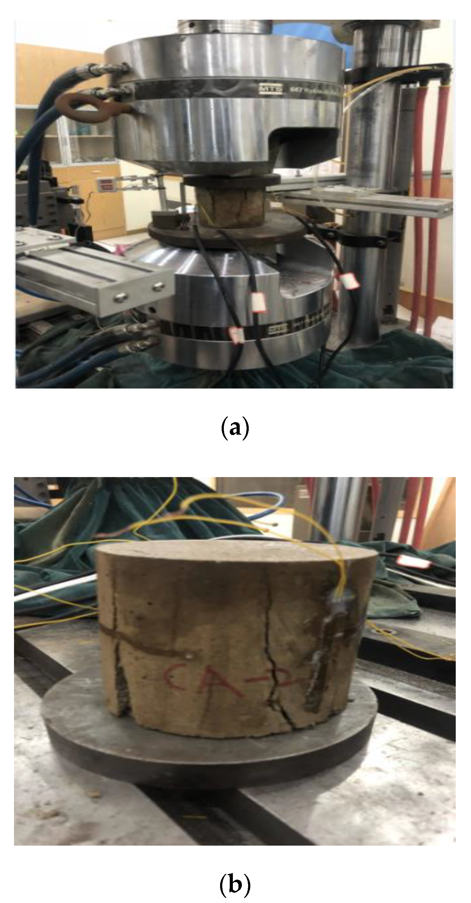
The uniaxial monotonic compressive tests were performed on an electric hydraulic servo-controlled material testing system (MTS-322-T, MTS Systems Corporation, Eden Praire, MN, USA) with a maximum capacity of 500 kN and accuracy of ± 0.5 % as shown in Figure 2. In order to avoid the apparent increase of the compressive strength of specimen due to a restraint effect caused by friction between the CA mortar specimen and the loading platens [58], a specially treated smooth steel pad was inserted between specimens and loading platens during the experiment.
In this study, a displacement-controlled loading mode was selected with a constant rate of 0.5 mm/min. The specimens were preloaded three times under approximately one-third of the compressive strengths (5 MPa) before formal experiments. In order to obtain relevant mechanical behaviors of CA mortar, the global deformations in the vertical direction of specimens were monitored by setting up an extensometer as illustrated in Figure 3. The outputs of the extensometers (MTS Systems Corporation, Eden Praire, MN, USA) were collected by means of the built-in data acquisition system of the closed-loop control system. The whole process of loading was recorded until the specimen completely failed.

3. Experimental Results and Discussion

3.1. Failure Mode

Due to the complexity of the damage and failure evolution in CA mortar, the failure modes are strongly dependent on the loading and boundary conditions during the test. In order to have a clear understanding of the mechanical properties of CA Mortar and relative failure mechanism during this test, it is necessary to study the failure modes of specimens. Figure 3b shows the observed failure of CA mortar. It can be seen that a typical ductile failure mode appeared during the experiment, since several cracks could be noticed with partial splitting, the specimens also maintained their integrity. Under axial loading, microcracks in the transition zone linking hardened cement paste and asphalt membrane expanded rapidly, forming several randomly distributed observed macrocracks nucleated and propagated parallel to the loading direction in the specimen until splitting into several parts. The experimentally observed crack usually occurred when axial strain was up to 2.5%–4%. In addition, due to the stability of the ascending and descending stage by using strain-controlled loading pattern, large deformations were observed before failure for CA mortar specimens.

3.2. Strengths and Critical Strain

The strengths and critical strain data are summarized in Table 6. In this study, critical strain is defined as the strain measured at the ultimate compressive strength of the CA mortar. In detail, the values of the compressive strengths are fluctuated between 14.09 MPa and 17.65 MPa, with a mean value of 15.23 MPa and standard deviation of 1.83 MPa.

3.3. Young’s Modulus

3.3.1. Initial Young’s Modulus

The initial elastic modulus is taken as the slope of the best-fit line through the stress–strain curve between 0% and 30% of the peak stress and is provided in Table 7. Specifically, the values of the Young’s modulus fluctuated between 2350.86 MPa and 4239.79 MPa, with a mean value of 3359.53 MPa and standard deviation of 611.00 MPa.

3.3.2. Secant Young’s Modulus

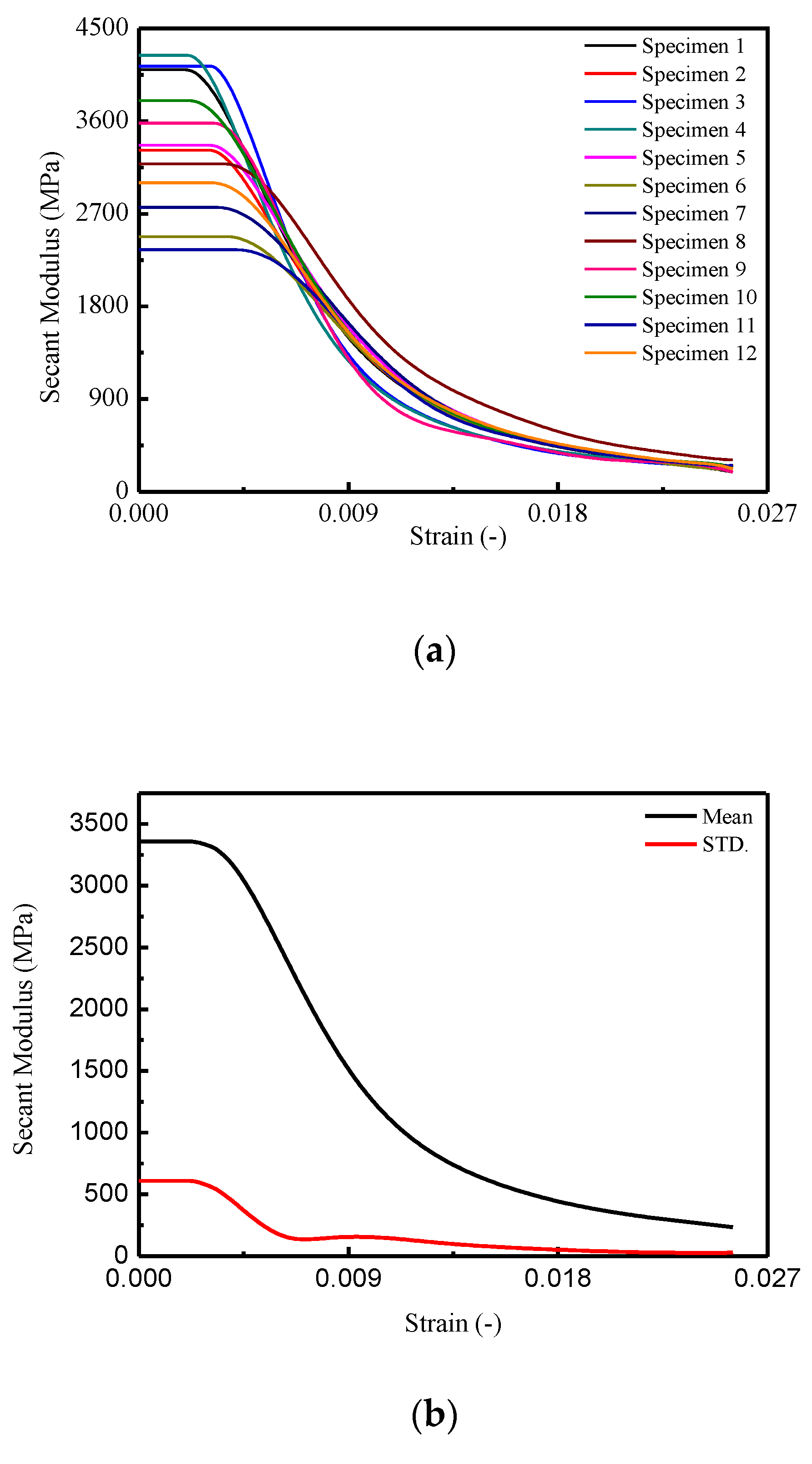
The secant Young’s modulus E s i for a certain stress–strain curve and the mean and standard deviation values of the secant Young’s modulus, E s ( ε ) and S T D E s . ( ε ) , are obtained from the following equations, the results of which are plotted in Figure 4.
E s i ( ε ) = σ i ε i
E s ( ε ) = 1 N j = 1 N E s j ( ε )
S T D E S . ( ε ) = 1 N 1 j = 1 N [ E s j ( ε ) E s ¯ ( ε ) ] 2
where E si , σ i , and ε i denote the i-th secant Young’s modulus, stress and strain for a certain stress–strain curve, respectively. E s ( ε ) and S T D E s . ( ε ) denote the values of the mean and standard deviation of the secant modulus for the 12 stress–strain curves, respectively. N denotes the total numbers of the stress–strain curves.
In Figure 4a, it is observed that the maximum secant modulus ranged from 2350.86 MPa to 4239.79 MPa and underwent different descending branches until to the minimum value ranged from 190.33 MPa to 309.92 MPa at a corresponding strain of 0.0255. In Figure 4b, the mean secant modulus was initially 3359.53 MPa, then decreased with increasing of strain to 233.83 MPa. The STD E s . ( ε ) for the specimens is varied from 611.00 MPa to 30.25 MPa. Precisely, it is found that after a dramatic drop before the strain reached 0.0065, the curve of S T D E s . ( ε ) began to decrease at a slower rate.

3.4. Complete Stress–Strain Curves

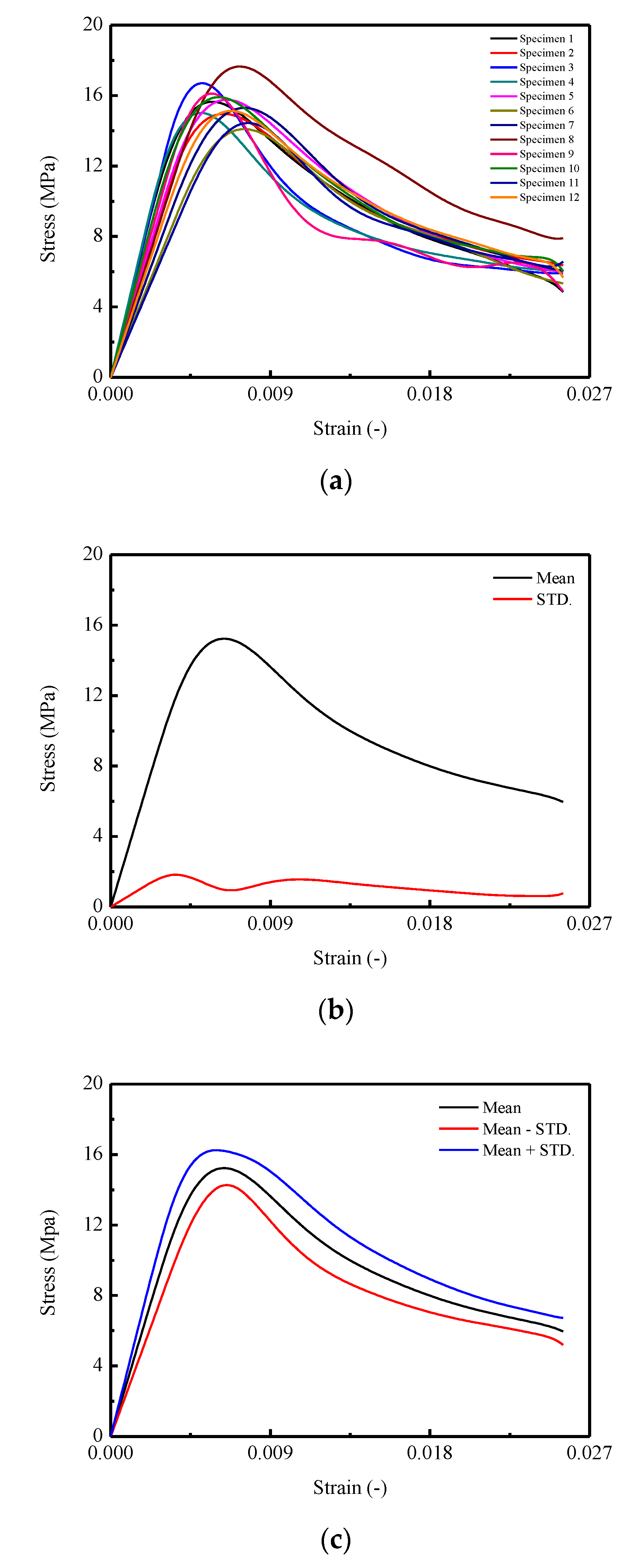
Stress–strain behavior is one of the most important features in evaluating the mechanical characteristics of the materials. Therefore, the complete stress–strain curves under uniaxial compression were obtained and plotted in Figure 5. Due to the intrinsic randomness and complexity of CA mortar, there was a certain variance among those full curves measured under the same loading conditions.
In detail, assume σ i = σ i ( ε ) represents the i-th full curve measured in the experiment. According to the statistics theory, the average curve (mean stress σ ¯ ( ε ) ) and the standard deviation STD σ . ( ε ) are capable of representing the integral trend and the variability for the experimental results. By adopting the following equations, the resulting mean stress–strain curve and the standard deviation curve are plotted in Figure 5b.
σ ¯ ( ε ) = 1 N i = 1 N σ i ( ε )
S T D σ . ( ε ) = 1 N 1 i = 1 N [ σ i ( ε ) σ ¯ ( ε ) ] 2
where σ ¯ ( ε ) and STD σ . ( ε ) denote the mean stress and the standard deviation corresponds to the strain ε , respectively. N denotes the total number of stress–strain curves, and σ i ( ε ) denotes the stress corresponding to the strain ε in i-th stress–strain curve.
The complete stress–strain curves are plotted in Figure 5a, in which the nonlinearities of the stress–strain behaviors are fully captured while some researchers focus on discovering certain mechanical behaviors (e.g., strength, Young’s modulus) [11,22,48,59,60]. The corresponding average curve and standard deviation curve generated by Equations (4) and (5) are illustrated in Figure 5b. In Figure 5c, the mean and mean   ±   STD. curves are obtained. It is observed that the CA mortar shows apparent stochastic responses during the uniaxial monotonic compression test. In Figure 5a, it is found that the peak stresses in the stress–strain curves are varied from approximately 14.44 MPa to 17.65 MPa, with the corresponding strains of 0.0077 and 0.0073. In Figure 5b, the peak stress σ p in the mean stress–strain curve is 15.23 MPa with a corresponding strain of 0.0064, and the residual stress σ s is found to be around 6.01 MPa. Moreover, in the standard deviation curve, the peak stress is 1.83 MPa with a corresponding strain of 0.0037. It is also noted that, the strain corresponding to the peak stress is significantly larger than that in the mean stress–strain curve. In Figure 5c, it is shown that, in the ascending branch, the area enveloped by the mean ± STD. of the stress–strain curve is less than that in the descending post-peak (softening) branch, which reveals a smaller degree of variation appeared during the early loading stage.

3.5. Energy Dissipation

Energy dissipation reveals the damage evolution process for material under external load. In a closed system, the total input energy of certain material in monotonic compression case could be obtained by the following equation [8,61,62]:
U = U d + U e
where U ,   U d ,   U e denote the total input energy, dissipated strain energy, and elastic strain energy, respectively.
The total input energy U can be calculated as:
U = A h σ d ε
where A and h denote the cross-section area and the height of the specimen, respectively.
The elastic strain energy is calculated as:
U e = A h σ 2 2 E 0
where E 0 denotes the Young’s modulus of the material. It is worth stressing that when a material is subjected to an external load less than its yield strength, the difference between unloading modulus E u and Young’s modulus E 0 is negligible. However, by adopting the above equation, after the external load exceeded its yield strength, an underestimation will have occurred in the results of the elastic strain energy U e . Nevertheless, due to the fact of lacking experimental results for determining the unloading modulus E u and for simplicity purposes, the modulus adopted for relative calculations is selected as the Young’s modulus E 0 in this work with reference to the literature [8,62].
Therefore, the dissipated strain energy U e can be calculated as:
U d = U U e = A h ( σ d ε σ 2 2 E 0 )
Since the specimens for this test were of the same size, the input strain energy, dissipated strain energy, and elastic strain energy can be further expressed as:
A h W = A h W d + A h W e
where W ,   W d ,   W e denote the total input strain energy density, dissipated strain energy density, and elastic strain energy density, respectively.
Hence, the relationship among the input strain energy density, dissipated strain energy density, and elastic strain energy density can be expressed as:
W = W d + W e
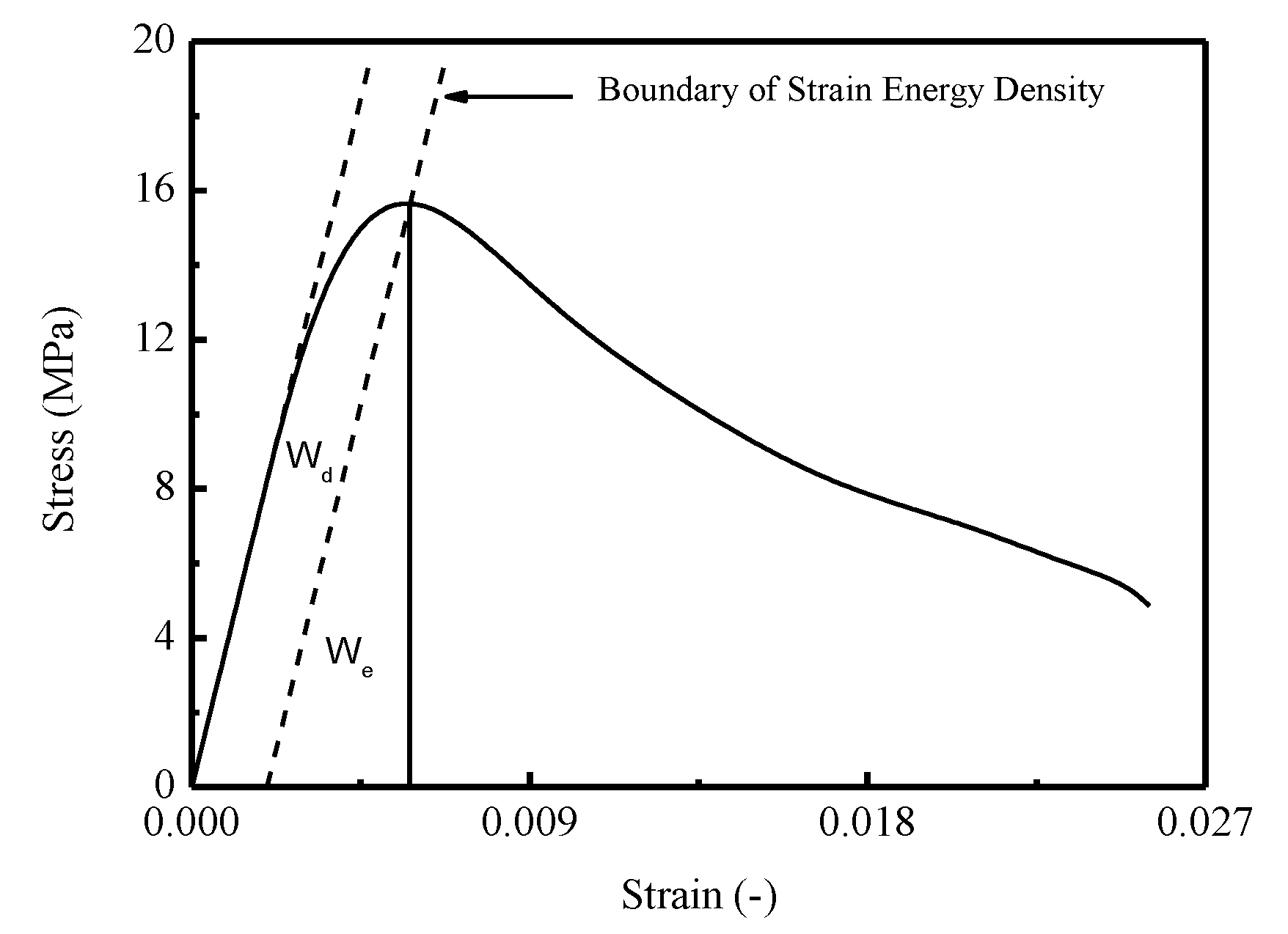
where W ,   W d ,   W e denote the total input strain energy density, dissipated strain energy density, and elastic strain energy density, respectively. A schematic diagram is illustrated in Figure 6.
Specifically, in Figure 6, the boundary of strain energy density is defined as a straight line with slope equals to the Young’s modulus of material. By constructing a line perpendicular to the horizontal axis from the point of intersection between the boundary of strain energy density and the stress–strain curve, the accumulative elastic strain energy density W e can be addressed. Moreover, the total input strain energy density W could be represented as the enclosed area by stress–strain curve, horizontal axis, and the line perpendicular to the x-axis correspond to current strain.
The total input strain energy density can be calculated by following equation:
W = 0 ε σ d ε
By assuming the strain energy boundary intersects with the stress–strain curve at point ( ε 1 , σ 1 ), it can be expressed as:
σ = E 0 ε + q
where q denotes the intercept between strain energy boundary and vertical axis.
Then the elastic strain energy density can be calculated by Equation (14):
W e = 1 2 ( ε 1 E 0 ε 1 σ 1 E 0 ) σ 1
The dissipated strain energy density is determined by the following equation:
W d = W W e
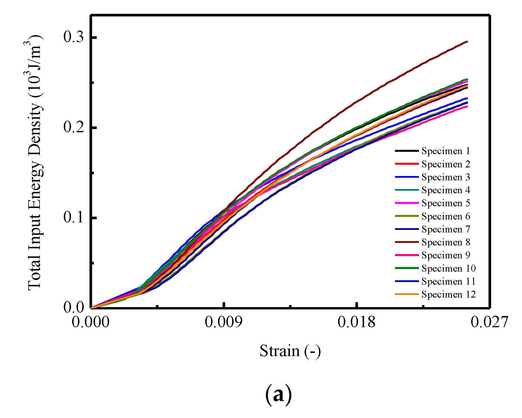
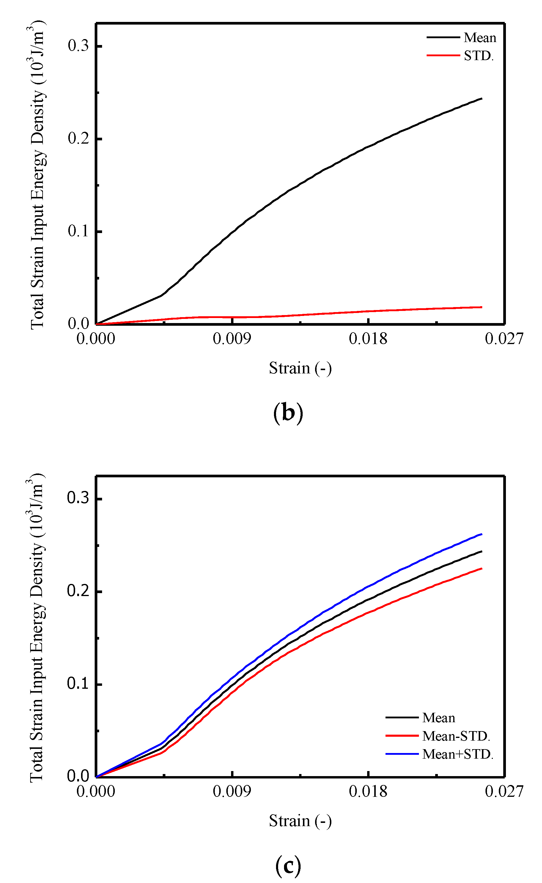
The calculated results of relative energy density with increased strain are shown in Figure 7. In Figure 7a, the total input strain energy density of CA mortar specimens under monotonic compression tests are given, with the mean and STD. curves illustrated in Figure 7b. It is found that for each specimen in Figure 7a, the total input strain energy density increased linearly until the strain reached approximately 0.005; then it turned into nonlinearity. The maximum total input strain energy densities varied between 0.224 ×   10 3   J / m 3 to 0.296 ×   10 3   J / m 3 . In Figure 7b,c, it is observed that the mean value and the STD. of the maximum input strain energy density are 0.244 ×   10 3   J / m 3 and 0.019 ×   10 3   J / m 3 .
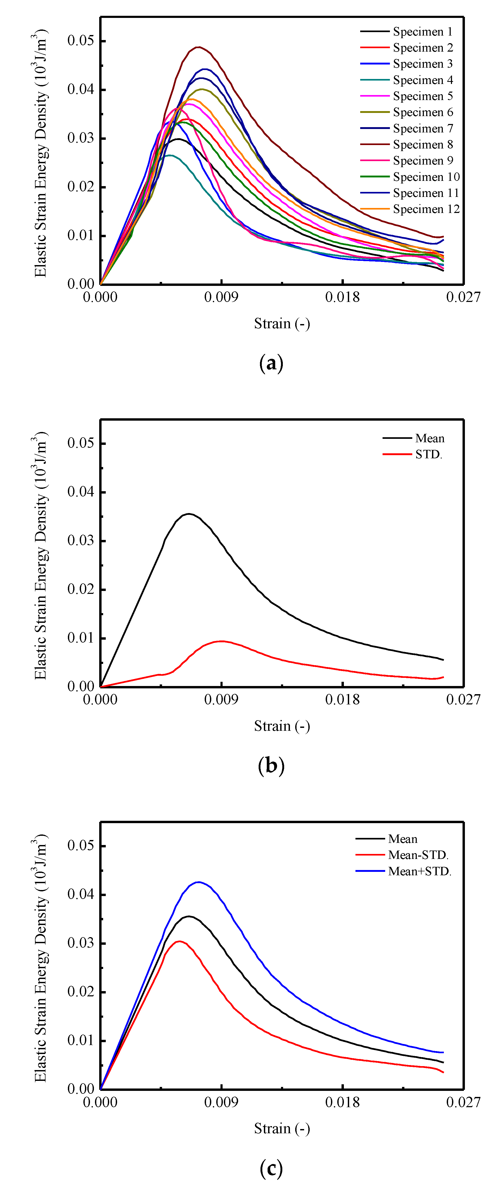
In Figure 8a, it is found that the curves of the elastic energy density for CA mortar specimens are similar to the stress–strain curves. In detail, during the early loading stage, the elastic strain energy densities linearly increased until the stress reached 80% of the peak stress, then the growing rates began to decrease. The maximum elastic strain energy densities varied between 0.027 ×   10 3   J / m 3 and 0.049 ×   10 3   J / m 3 . In Figure 8b,c, the maximum mean elastic strain energy density is 0.036 with a corresponding strain of 0.0066. The STD. of the elastic strain energy densities for CA mortar specimens first increased to 0.0025 ×   10 3   J / m 3 at the point of 80% of the peak stress approximately. Then it went up to the maximum value of 0.0094 ×   10 3   J / m 3 and decreased at a comparatively slowly rate to 0.00207 ×   10 3   J / m 3 .
In Figure 9a, the curves of dissipated strain energy densities for CA mortar specimens are similar to the total input strain energy density curves. The final values for the dissipated strain energy densities ranged from 0.219 ×   10 3   J / m 3 to 0.286 ×   10 3   J / m 3 . It is observed that in Figure 9b,c, the maximum mean dissipated strain energy density is 0.238 ×   10 3   J / m 3 with a corresponding STD. of 0.018 ×   10 3   J / m 3 .

3.6. Damage Model of Stress–Strain Relationship

In this section, a damage model able to characterize the stochastic behaviors of CA mortar during uniaxial compression is developed based on the BCM model proposed in the literature [53].

3.6.1. Brief Review of BCM

The BCM is developed based on the classical fiber bundle model (FBM) for characterizing the mechanical behaviors of materials. The model is considered as consisting of a bundle of parallel linearly elastic fibers assigned random fracture thresholds with a probability density of P d ( ε ) and a chian of linked perfect plastic sliders with random yield thresholds and a probability density P r ( ε ) .
After each failure event, the load carried by the intact fibers are redistributed (i.e., the equal-load sharing pattern), and the same plastic strain is produced by an individual slider after each sliding event once the yielding threshold is reached. Hence, the damage variable d(ε) (i.e., the accumulative distribution of the probability density) and the plastic variable (plastic ratio) r(ε) (i.e., the accumulative distribution of Pr(ε)) can be calculated based on the statistical method such as:
d ( ε ) = 0 ε P d ( ε ) d ε
r ( ε ) = 0 ε P r ( ε ) d ε
Hence, the total damage variable coupling the effects of both the elastic damage and plasticity, named plastic-damage variable dr ( ε ) , is defined as:
d r ( ε ) = d ( ε ) + r ( ε ) = 0 ε P d ( ε ) d ε + 0 ε P r ( ε ) d ε
Thus, the constitutive relationship for CA mortar can be modeled as follows:
σ = [ 1 d ( ε ) ] E 0 ε
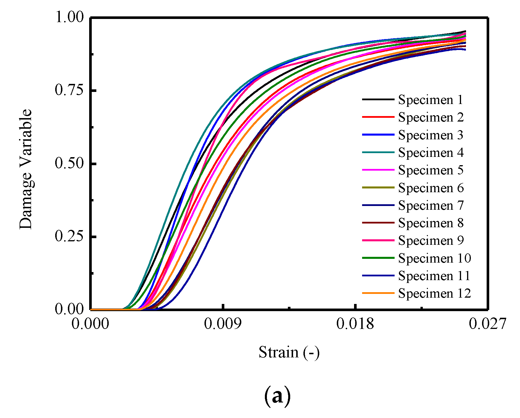
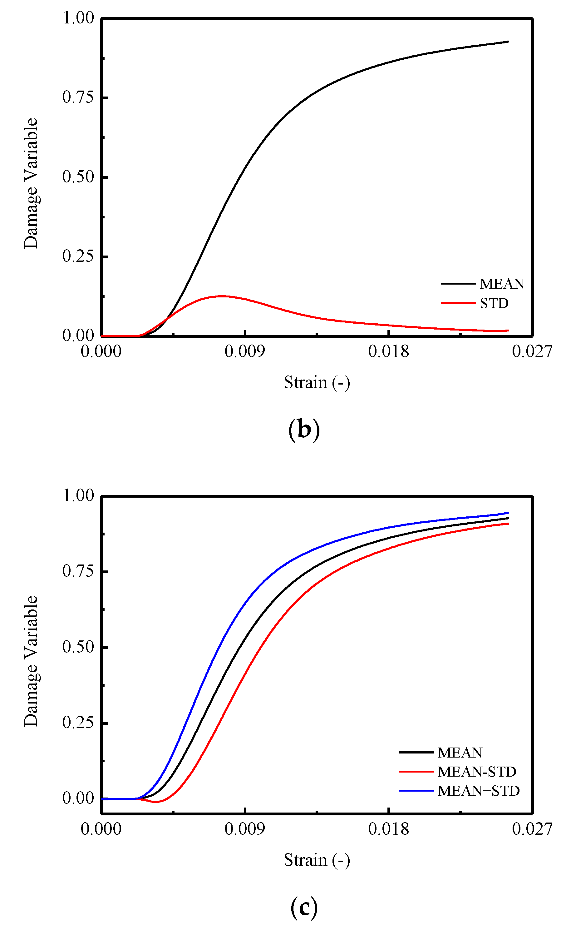
It is assumed in the monotonic compressive case, the plastic-damage variable is not involved during the loading process in this work. Hence, the values of the total damage for a certain stress–strain curve, as well as mean and standard deviations of the damage, for the twelve CA mortar specimen can be calculated by following equations, the results of which are plotted in Figure 10.
d i = 1 σ i / ε i E 0
d ( ε ) = 1 N j = 1 N d i ( ε )
S T D . ( ε ) = 1 N 1 j = 1 N [ d i ( ε ) d ¯ ( ε ) ] 2
where d i , σ i , ε i are the i-th damage variables, stress and strain for a certain stress–strain curve, respectively. D ( ε ) and STD ( ε ) denote the mean damage and its standard deviations for the ten stress–strain curves, respectively. N denotes the numbers of the stress–strain curves.

3.6.2. Analytical Model of CA Mortar

In order to develop an analytical constitutive model for CA mortar capable of characterizing the stochastic behaviors, the expressions for the mean and STD. of the damage variable d should be initially determined. By observing the calculated results illustrated in Figure 10, a logistic type function was adopted to depict the mean of the damage variable μ d ( ε ) :
μ d ( ε ) = A 1 A 2 1 + ( ε ε 0 ) p + A 2
where A 1 , A 2 , ε 0 , p denote the parameters relating to the mean of the stochastic damage evolution process. The parameters of the proposed model are determined by using a fitting method based on the experimental results shown in Figure 10b. The determined values of the parameters are listed in Table 8.
An Extreme type function was used to characterize the STD. of the damage variable S T D d ( ε ) in terms of total strain ε :
S T D d ( ε ) = A 3 e ( e Z Z + 1 )
Z = ( ε A 4 ) w
where A 3 , A 4 , and w denote the parameters related to the variation of the stochastic damage evolution process. The parameters of the proposed model were determined by using a fitting method based on the experimental results shown in Figure 10b. The determined values of the parameters are listed in Table 9.
Therefore, the mean stress–strain curve can be addressed in conjunction with Equation (19):
μ σ ( ε ) = ( 1 μ d ( ε ) ) E 0 ε
where μ σ ( ε ) denotes the mean stress corresponds to strain ε .
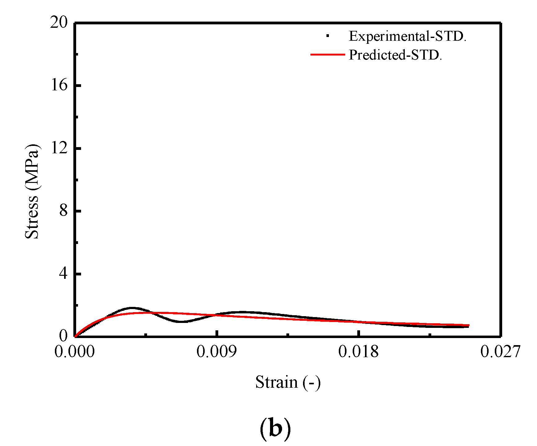
For characterizing the standard deviation of the stress–strain curve, the STD. of the stress S T D σ ( ε ) that corresponds to the strain ε is obtained by direct fitting of the experimental results in Figure 5b by adopting the Nelder type function:
S T D σ ( ε ) = ε b 0 + b 1 ε + b 2 ε 2
where b 0 , b 1 , and b 2 represent the parameters related to the stochastic behaviors of the stress–strain curve that appeared during loading. The determined values of the parameters are listed in Table 10.

3.6.3. Model Verification

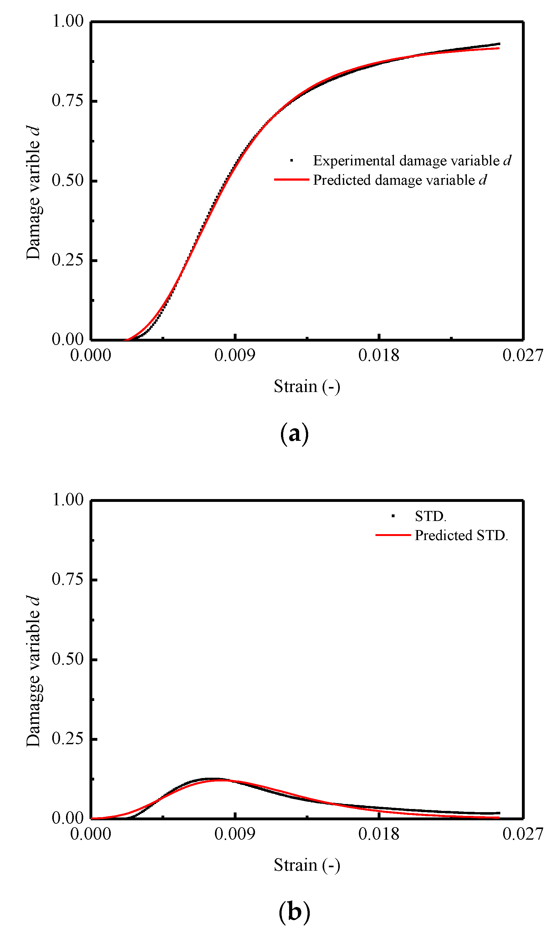
In order to verify the effectiveness of the proposed model in this work, it has been validated by means of comparison with the predictions and experimental results. Figure 11 and Figure 12 show the comparison of the results in terms of mean and STD. of the damage variable d and stress–strain curves for CA mortar specimens, respectively. It is observed that a very good matching between the predicted and experimental results in both of the two figures is obtained. However, in Figure 11a, the predicted mean of the damage variable μ d ( ε ) is found to be somewhat underestimated when compared to the experimental result. Consequently, it results in an overestimation for the value of mean stress μ σ ( ε ) after the corresponding strain exceeding 0.20.
In summary, by examining the comparison results between the predictions and the experimental results in this work, it is verified that the proposed model is able to characterize the stochastic constitutive relationship (nonlinear and random stress–strain behaviors) of CA mortar under uniaxial monotonic compression with clear physical meaning based on a statistical damage approach, while some researchers used empirical relationships to predict certain mechanical behaviors of materials [11,22,24,25,48,59,60].
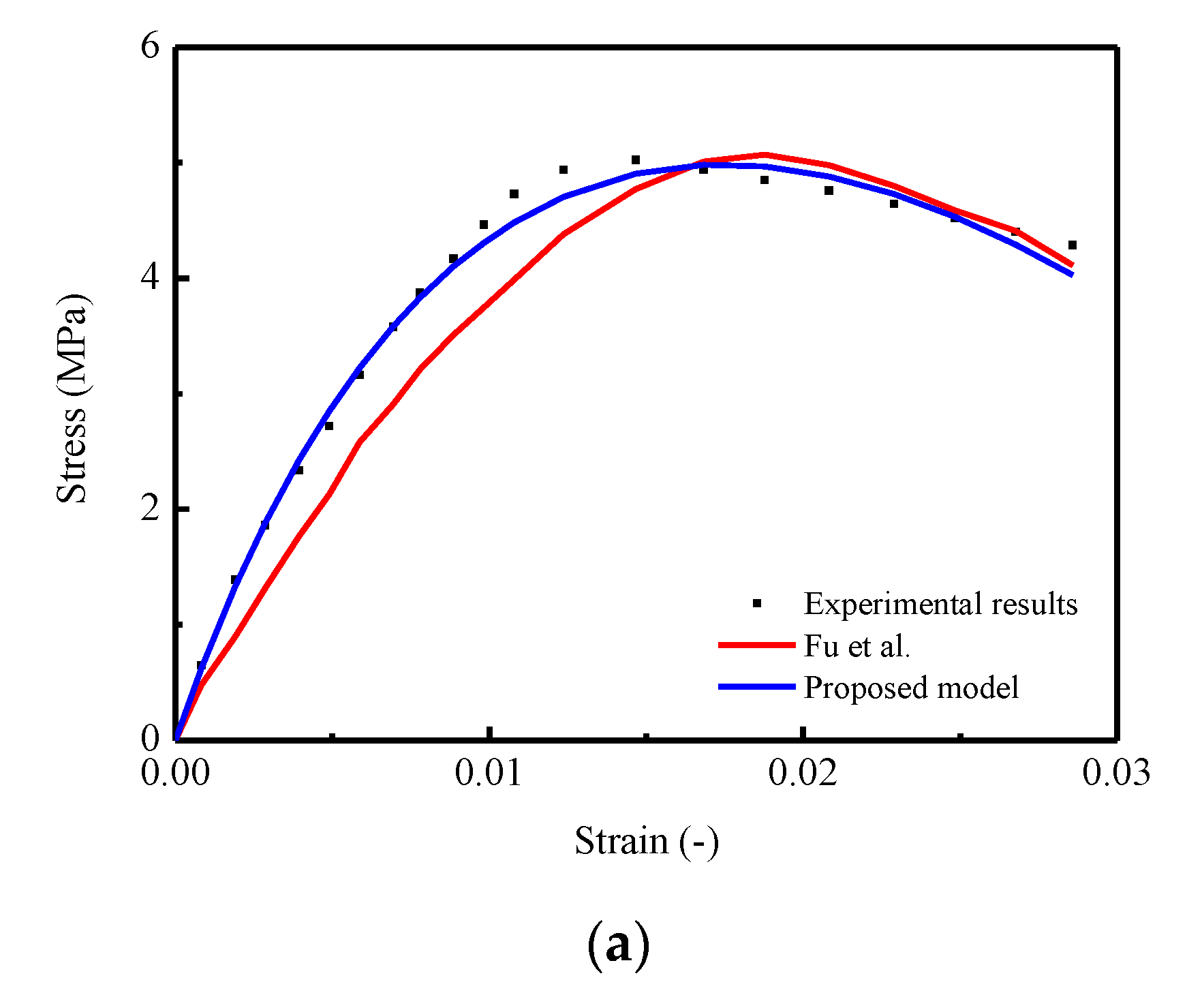
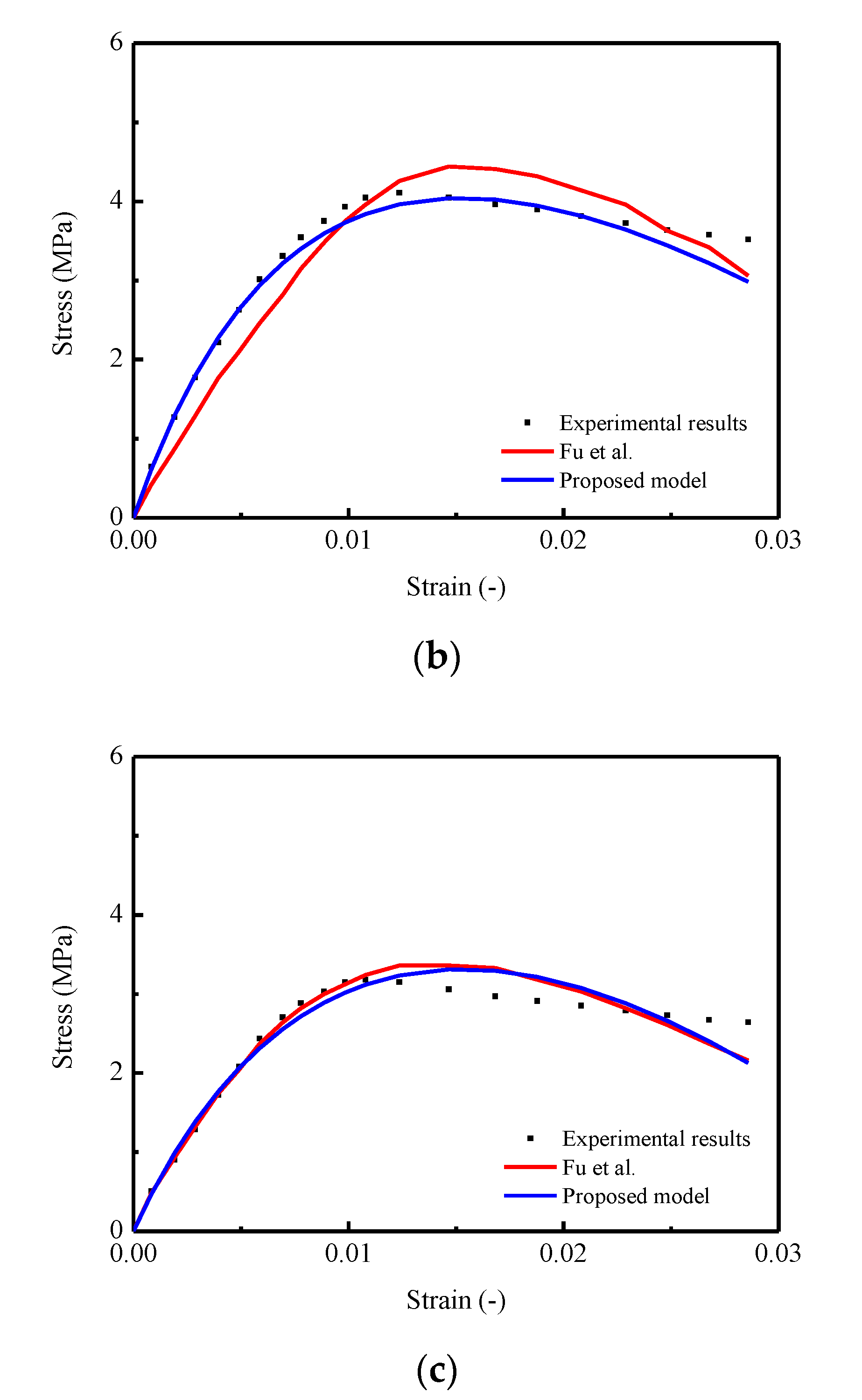
In addition, from a practical point of view, although the proposed model can capture the nonlinearity and randomness of the stress–strain behavior, a number of models based on empirical and theoretical approaches proposed in foregoing studies [8,21,22,23,24,25,35,46,47,48,49,50,51,52,53,54,59,60,63] also provide lucid and acceptable results to predict relevant mechanical properties of certain materials. Thus, in order to further verify the applicability and accuracy for the proposed model, a comparison between the predicted mean stress–strain curve by using the proposed model and the model developed by Fu et al. mentioned in the literature [35] were conducted. In detail, three stress–strain curves of CA mortar under uniaxial monotonic compressive test with strain rates of 0.0033 / m s 1 , 0.17 / m s 1 , and 1.7 / m s 1 were selected for the verification process, and the results are illustrated diagrammatically in Figure 13. The observation shows that the predicted stress–strain curve generated by the proposed model is closer to the experimental results. Specifically, in Figure 13a,b, a certain degree of underestimations of the stresses in the ascending branch and overestimations in the descending branch are found for the predictions by Fu et al. In Figure 13c, it seems that the differences in the predicted curves by these two models are relatively small. Furthermore, by considering the lack of capability for characterizing the stochastic behaviors (variance), the applicability of the proposed model is wider, to some extent, compared with the presented model mentioned in this work.

4. Further Discussion

4.1. Transition from Microscale to Macroscale

For the purpose of understanding the intrinsic random nature for materials in the aspect of varied scales, it is essential to focus on the issue of the media process in terms of the transition from microscale to macroscale.
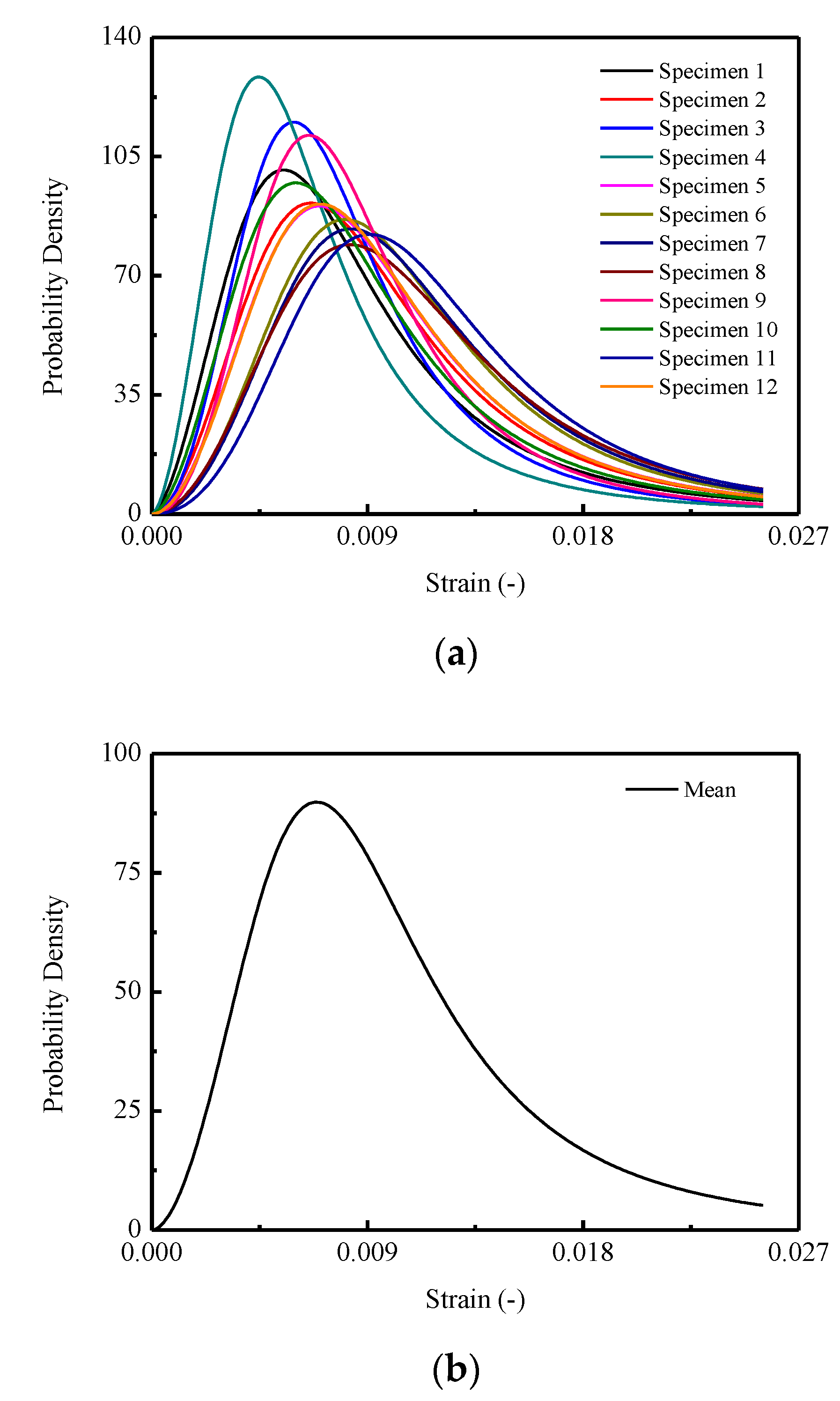
Figure 14 demonstrates the stochastic and the mean behaviors of the probability density for the damage variable d in the perspective of microscale. The probability density can be obtained by differentiating the relative damage evolution function, viz., Equation (23). Specifically, in Figure 13a, it is illustrated that different probability densities are endowed for CA mortar specimens induced by the randomness of the microstructure, consequently resulting in the varieties of the damage evolution processes during loading stage.
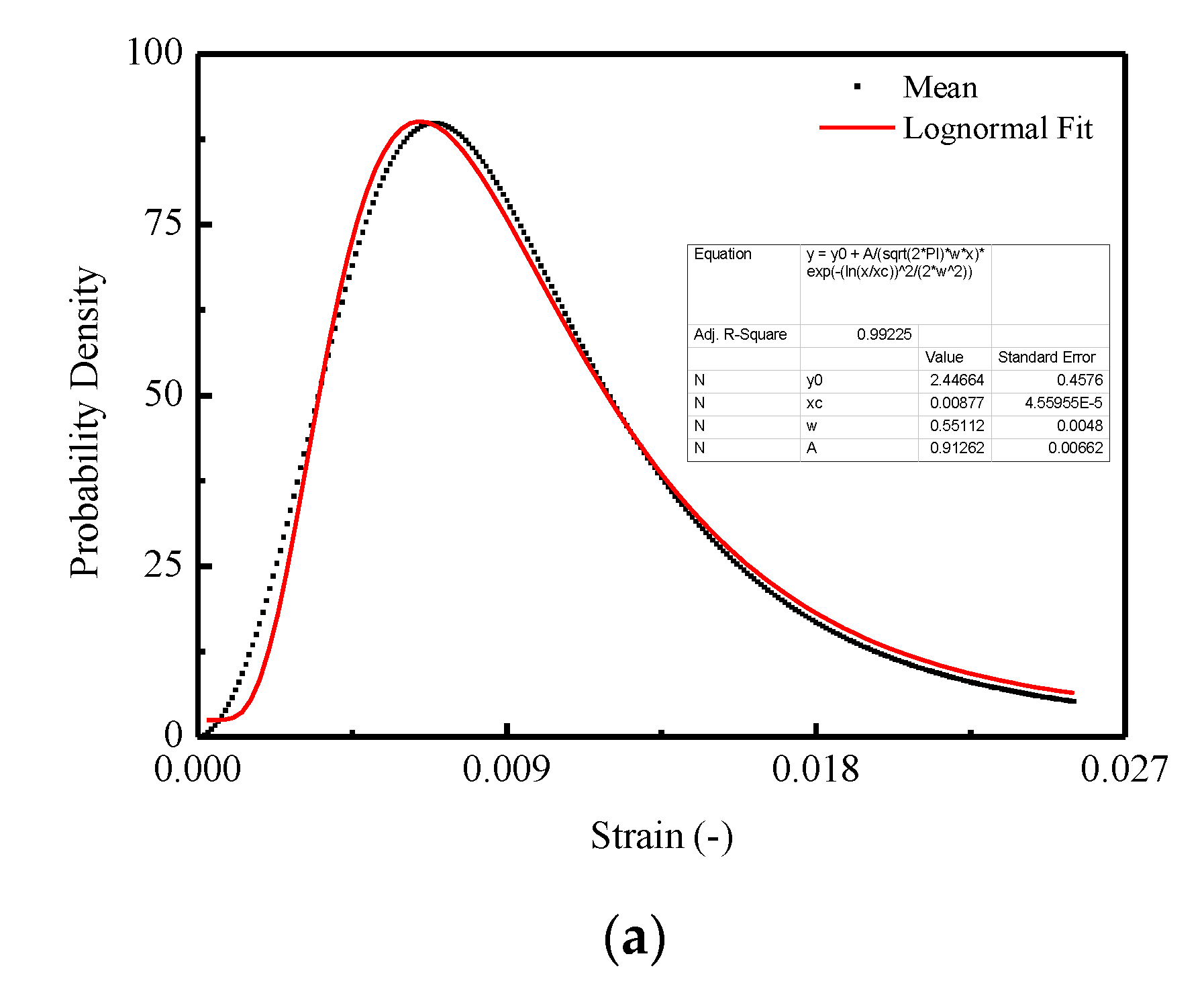
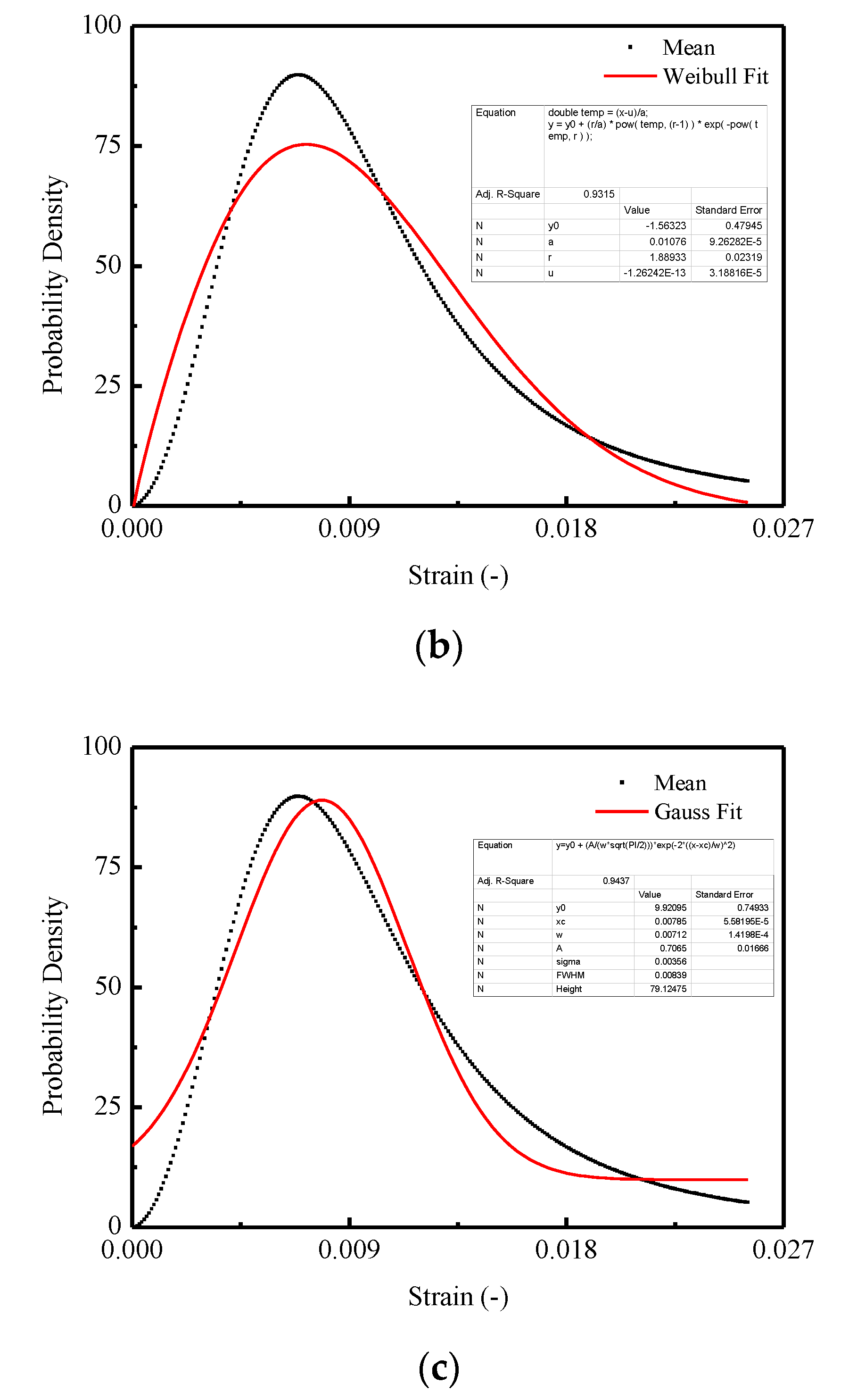
In Figure 15, three commonly used density functions in the statistical damage approach are examined by fitting the mean curve shown in Figure 13b. It is indicated that the best agreement is obtained for CA mortar by adopting the Lognormal distribution function, which is represented in Figure 15a, when compared with the Weibull distribution function in Figure 15b and Gauss distribution function in Figure 15c.
Moreover, the stochastic evolution (SE) illustrated in Figure 4 (in terms of elastic modulus degradation) and in Figure 10 (in terms of damage accumulation) are also indispensable for investigating the media process of CA mortar under loading. Precisely, the SE demonstrates the stochastic media process of transition from microscale (microstructure) to macroscale (macroresponse). It is concluded that the progressive accumulation of the damage with different probability densities mentioned above is treated as the main cause for the SE of the damage variable d . The SE of the damage variable d results in the stochastic degradation of the elastic modulus plotted in Figure 4 and the stochastic damage evolutions in Figure 10, which consequently result in the stochastic stress–strain relationships of CA mortar.

4.2. Comparison of Constitutive Relationships among CA Mortar for CRTS I, II and Concrete under Monotonic Uniaxial Compression

In this section, the comparisons of the mean compressive constitutive relationships among the CA mortar studied in this work (CRTS-II type CA mortar), typical CRTS-I CA mortar, and concrete are obtained by examining on the strain–stress responses, evolutions of damage variables, and probability density. The relevant experimental data used in this sub-section are obtained from the literature [21,51].
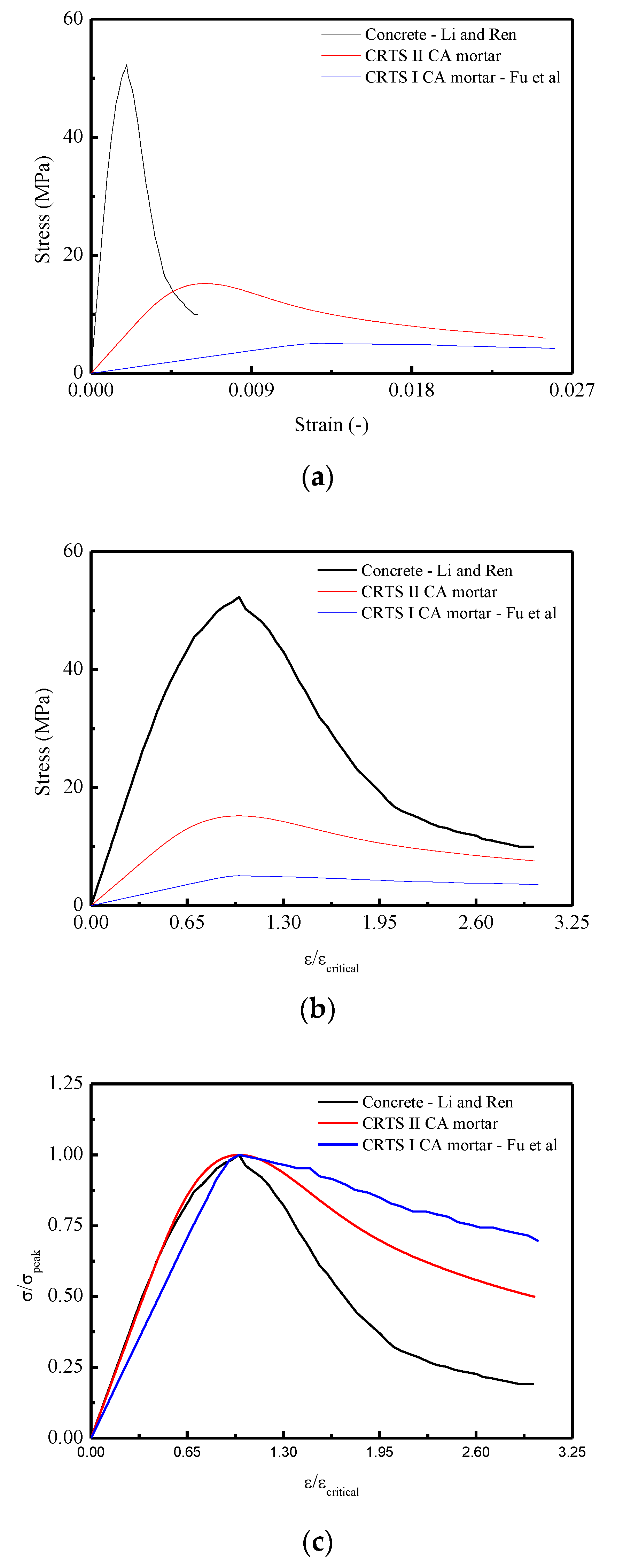
Figure 16a shows the compressive stress–strain responses for the three materials. It is found that the largest peak stress occurs in the stress–strain curve of concrete, which is approximately 3.5 times larger than CRTS-II type CA mortar and 10 times larger than CRTS-I type CA mortar. Figure 16b,c represents the stress–strain responses by examining the relationships of normalized strain ( ε / ε c r i t i c a l ) versus stress σ and normalized strain ( ε / ε c r i t i c a l ) versus normalized stress ( σ / σ p e a k ) . It is revealed that the flattest response appeared in the relevant curve for CRTS-I CA mortar. The reasons can be attributed to CRTS-I type CA mortar being more ductile when compared with concrete and CRTS-II type CA mortar, which results in the appearance of the lowest peak stress among the three materials.
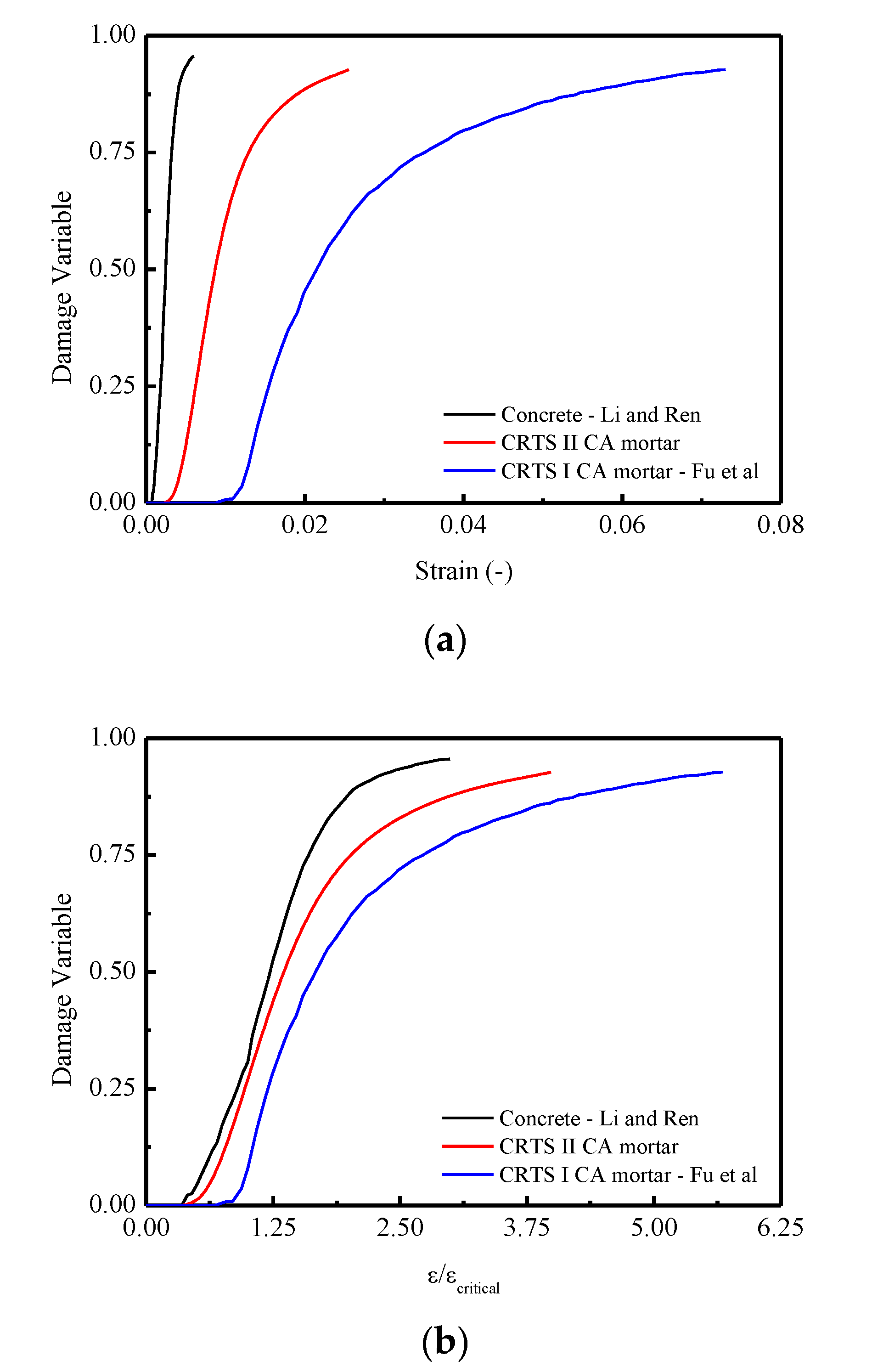
Figure 17a,b illustrated the evolution of the damage variable in terms of strain ε and normalized strain ( ε / ε c r i t i c a l ) . It is found that that concrete has the most intensive development of the damage, as shown in Figure 17a, when compared to CRTS-II and I type CA mortars. A more apparent appearance can be noticed in Figure 17b when the curve is constructed in terms of damage variable versus the normalized strain ( ε / ε c r i t i c a l ) . More precisely, it is observed that when the value of normalized strain ( ε / ε c r i t i c a l ) reaches approximately 2.99, the values of the damage variable d for CRTS II CA mortar, CRTS I CA mortar, and concrete are 0.877, 0.789, and 0.956, respectively. The reasons can be concluded as follows: due to the existence of the viscoelasticity or viscoplasticity in the CRTS II CA mortar and CRTS I CA mortar, the evolution of the damage for these two materials are comparatively slower than a quasi-brittle material like concrete.
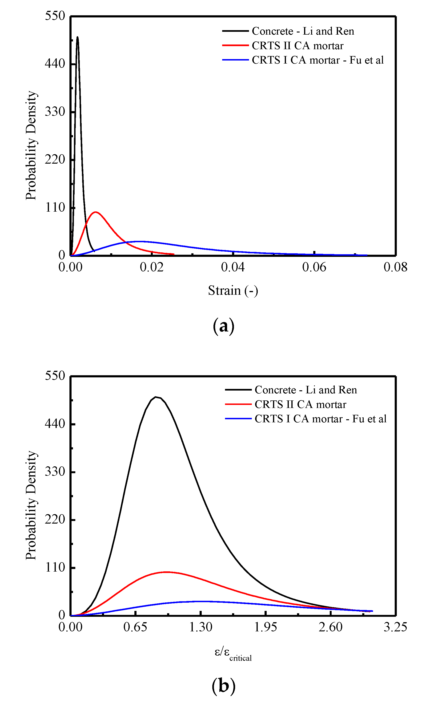
Figure 18 plots the developments of probability density in terms of strain and normalized strain ( ε / ε c r i t i c a l ) , respectively. It is observed that the two curves are similar to the stress–strain curve discussed above. It is concluded that the lowest concentration of the probability density curve of CRTS-I CA mortar contributes to a less intensive development of the damage variable and consequently leads to the most ductile stress–strain response. In detail, the causes for such different probability densities emerging in the three materials could be attributed to their various microstructures: Concrete is a quasi-brittle material and considered a three-phase composite material, consisting of aggregated particles, the cement paste matrix, and the interfacial transition zones around the aggregated particles [64]. Different from concrete, CA mortar is considered a two-phase composite composed of inorganic binder-cement and organic binder-asphalt [22,65,66]. Mechanical performance of such composites is a joint reflection of both binders’ properties. Thus, the cement is a hydraulic binder and its hydration products are brittle, whereas the asphalt is a viscoelastic binder with a much lower stiffness [46,67]. At low asphalt emulsion contents (CRTS-II type CA mortar), the phase of the cement hydrates acts as a bulk matrix in the binder of mortar with asphalt dispersed in it. For CA mortar with higher emulsion contents (CRTS-I type CA mortar), the asphalt phase becomes dominant and the cement hydrates play the role of the dispersed phase [68,69].

5. Conclusions

In this work, the compressive behaviors of CA mortar under uniaxial monotonic loading were experimentally investigated by taking into account the stochastic properties. In order to characterize the stochastic behaviors of CA mortar, an analytical stochastic constitutive model based on the statistical damage approach was proposed. Furthermore, the media process of transition from microscale to macroscale for CA mortar under compression and the comparisons with typical CRTS I CA mortar and concrete in terms of constitutive behaviors have also been demonstrated and conducted. Conclusions can be drawn as follows:
(1)
The experimental results indicate that there are considerable variations in the mechanical responses including: compressive strength, critical strain, Young’s modulus, and stress–strain curve for CA mortar specimens with the same mix proportions, even when identically prepared.
(2)
An analytical model based on the statistical damage approach was developed to describe the stochastic constitutive stress–strain relationship of CA mortar. The proposed model is capable of evaluating the mean and the standard deviation of stress–strain curves. The validation of the proposed model was performed by comparison between the predictions and the experimental results. It was shown that there is a relatively good coincidence between the predictions and the experimental results. In addition, a comparison of predictions in terms of the mean stress–strain curve by the proposed model and those obtained by the model in a previous study was also conducted, which revealed that by adopting the proposed model, the accuracy of prediction is improved.
(3)
Further exploration of the behaviors of CA mortar was obtained by examining the media process in terms of transition from microscale (microstructure) to macroscale (macroresponse). It is found that the Lognormal distribution density function can well represent the damage probability density for CA mortar under compression when compared to the Weibull and Gauss distribution density functions. It is also summarized that the stochastic behaviors that emerged for CA mortar are attributed to the randomness of the damage probability density at the microscale. The media process of the transition during the loading process is represented by the stochastic evolution (SE) of specific variables at the macroscale.
(4)
Comparisons of the constitutive relationships among the CA mortar used in this work, typical CRTS-I type CA mortar, and concrete were conducted. It was demonstrated that the most ductile stress–strain response was obtained by CRTS-I CA mortar due to its lowest concentration in the probability density curve induced by the microstructure.

Author Contributions

Writing—original draft preparation, X.L.; investigation, P.L.; conceptualization, Z.Y. and Z.S.; methodology, Z.M. All authors have read and agree to the published version of the manuscript.

Funding

This study was funded by the National Natural Science Foundation of China, grant numbers 51778632, U1434204, U1934217 and 51408614, the China Postdoctoral Science Foundation, grant numbers 2016M600675, 2017T100647 and 2018M642658, the Basic Research on Science and Technology Program of Shenzhen, grant numbers JCYJ20170818143541342 and JCYJ20180305123935198, the National Engineering Laboratory for High Speed Railway Construction of China, grant number HSR201903, and the Natural Science Foundation of Hunan Province of China, grant number 2017JJ3385.

Conflicts of Interest

The authors declare no conflict of interest.

References

  1. Esveld, C. Recent development in slab track. Eur. Railw. Rev. 2003, 9, 81–85. [Google Scholar]
  2. Miura, S.; Takai, H.; Uchida, M.; Fukada, Y. The mechanism of railway tracks. Jpn. Railw. Transp. Rev. 1998, 15, 38–45. [Google Scholar]
  3. Katsuoshi, A. Development of slab tracks for Hokuriku Shinkaren line, Quarterly Report of RITI. Railw. Tech. Res. Inst. 2003, 42, 35–41. [Google Scholar]
  4. Du, J.C.; Kuo, M.F.; Yeh, J.C. Properties of cement asphalt emulsion mortar for pavement. Cem. Concr. Res. Adv. Mater. Res. 2013, 723, 466–473. [Google Scholar] [CrossRef]
  5. Li, G.; Zhao, Y.; Pang, S.S.; Huang, W. Experimental study of cement-asphalt emulsion composite. Cem. Concr. Res. 1998, 5, 635–641. [Google Scholar] [CrossRef]
  6. Wang, J.; Molenaar, A.A.A.; van de Ven, M.F.C.; Wu, S. Behaviour of asphalt concrete mixtures under tri-axial compression. Constr. Build. Mater. 2016, 105, 269–274. [Google Scholar] [CrossRef]
  7. Ouyang, J.; Han, B.G.; Cao, Y.; Zhou, W.J.; Li, W.; Shah, S.P. The role and interaction of superplasticizer and emulsifier in fresh cement asphalt emulsion paste through rheology study. Constr. Build. Mater. 2016, 125, 643–653. [Google Scholar] [CrossRef] [Green Version]
  8. Xie, Y.J.; Fu, Q.; Zheng, K.R.; Yuan, Q.; Song, H. Dynamic mechanical properties of cement and asphalt mortar based on SHPB test. Constr. Build. Mater. 2014, 70, 217–225. [Google Scholar] [CrossRef]
  9. Zeng, X.H.; Xie, Y.J.; Deng, D.H. Conductivity behavior of the fresh CA mortar and its relationship with the fluidity properties. Constr. Build. Mater. 2012, 36, 890–894. [Google Scholar] [CrossRef]
  10. Wang, F.Z.; Liu, Z.C.; Hu, S.G. Early age volume change of cement asphalt mortar in the presence of aluminum powder. Mater. Struct. 2010, 43, 493–498. [Google Scholar] [CrossRef]
  11. Wang, Z.J.; Shu, X.; Rutherford, T.; Huang, B.S.; Clake, D. Effects of asphalt emulsion on properties of fresh cement emulsified asphalt mortar. Constr. Build. Mater. 2015, 75, 25–30. [Google Scholar] [CrossRef]
  12. Tan, Y.Q.; Ouyang, J.; Li, Y.L. Factors influencing rheological properties of fresh cement asphalt emulsion paste. Constr. Build. Mater. 2014, 68, 611–617. [Google Scholar] [CrossRef]
  13. Peng, J.W.; Deng, D.H.; Huang, H.; Yuan, Q.; Peng, J.G. Influence of superplasticizer on the rheology of fresh cement asphalt paste. Case Stud. Constr. Mater. 2015, 3, 9–18. [Google Scholar] [CrossRef] [Green Version]
  14. Peng, J.W.; Deng, D.H.; Liu, Z.Q.; Yuan, Q.; Ye, T. Rheological models for fresh cement asphalt paste. Constr. Build. Mater. 2014, 71, 254–262. [Google Scholar] [CrossRef]
  15. Ouyang, J.; Tan, Y.Q. Rheology of fresh cement asphalt emulsion pastes. Constr. Build. Mater. 2015, 80, 236–243. [Google Scholar] [CrossRef]
  16. Peng, J.W.; Deng, D.H.; Yuan, Q.; Liu, Z.Q.; Fang, L. Study of the rheological behavior of fresh cement emulsified asphalt paste. Constr. Build. Mater. 2014, 66, 348–355. [Google Scholar] [CrossRef]
  17. Zhang, Y.R.; Kong, X.M.; Hou, S.S.; Liu, Y.L.; Han, S. Study on the rheological properties of fresh cement asphalt paste. Constr. Build. Mater. 2012, 27, 534–544. [Google Scholar] [CrossRef]
  18. Ouyang, J.; Tan, Y.Q.; Corr, D.J.; Shah, S.P. The thixotropic behavior of fresh cement asphalt emulsion paste. Constr. Build. Mater. 2016, 114, 906–912. [Google Scholar] [CrossRef]
  19. Wang, T.; Jia, H.Q.; Li, H.G.; Li, H.Y.; Shao, P.Y. Research on water seepage of cement asphalt emulsified (CA) mortar. Constr. Build. Mater. 2016, 125, 595–599. [Google Scholar] [CrossRef]
  20. Song, H.; Do, J.; Soh, Y. Feasibility study of asphalt-modified mortars using asphalt emulsion. Constr. Build. Mater. 2006, 20, 332–337. [Google Scholar] [CrossRef]
  21. Fu, Q.; Xie, Y.J.; Song, H.; Zhou, X.L. Model for Mechanical Properties of Cement and Asphalt Mortar. J. Chin. Ceram. Soc. 2014, 42, 1396–1403. (In Chinese) [Google Scholar]
  22. Rutherford, T.; Wang, Z.J.; Shu, X.; Huang, B.S.; Clarke, D. Laboratory investigation into mechanical properties of cement emulsified asphalt mortar. Constr. Build. Mater. 2014, 65, 76–83. [Google Scholar] [CrossRef]
  23. Fu, Q.; Xie, Y.J.; Zheng, K.R.; Song, H.; Zhou, X.L. Strain Rate Effect and Modeling of Mechanical Properties of CRTS II Type Cement and Asphalt Mortar. J. Chin. Ceram. Soc. 2014, 42, 989–995. (In Chinese) [Google Scholar]
  24. Wang, J.F.; Chen, Y.R.; Fan, X.L.; Li, J.Z. Effects of strain rate and confining pressure on compressive behavior of cement asphalt mortar. Mater. Des. 2015, 65, 772–779. [Google Scholar] [CrossRef]
  25. Wang, J.F.; Wu, X.; Fan, X.L.; Chen, Y.R. Stress-strain model of cement asphalt mortar subjected to temperature and loading rate. Constr. Build. Mater. 2016, 111, 164–174. [Google Scholar] [CrossRef]
  26. Wang, F.Z.; Liu, Z.C.; Hu, S.G. Influence of loading rate on compressive strength of CA mortar. Beijing Univ. Technol. 2008, 34, 59–65. (In Chinese) [Google Scholar]
  27. Liu, X.Y.; Wang, P. Dynamics of Vehicle-Track-Subgrade System; SWJT University Press: Chengdu, China, 2010. (In Chinese) [Google Scholar]
  28. Zeng, X.H.; Xie, Y.J.; Deng, D.H.; Wang, P.; Qu, F.L. A study of the dynamic mechanical properties of CRTS I type CA mortar. Constr. Build. Mater. 2016, 112, 93–99. [Google Scholar] [CrossRef] [Green Version]
  29. Fu, Q.; Xie, Y.J.; Long, G.C.; Niu, D.T.; Song, H. Dynamic mechanical thermo-analysis of cement and asphalt mortar. Powder Technol. 2017, 313, 36–43. [Google Scholar] [CrossRef]
  30. Cao, J.Y.; Chung, D.D.L. Effect of strain rate on cement mortar under compression, studied by electrical resistivity measurement. Cem. Concr. Res. 2002, 32, 817–819. [Google Scholar] [CrossRef]
  31. Fu, Q.; Xie, Y.J.; Long, G.C.; Niu, D.T.; Song, H.; Liu, X.G. Impact characterization and modelling of cement and asphalt mortar based on SHPB experiments. Int. J. Impact Eng. 2017, 106, 44–52. [Google Scholar] [CrossRef]
  32. Liu, Y.L.; Kong, X.M.; Zhang, Y.R.; Yan, P.Y. Static and dynamic mechanical properties of cement-asphalt composites. J. Mater. Civ. Eng. 2013, 25, 1489–1497. [Google Scholar]
  33. Kong, X.M.; Liu, Y.L.; Zhang, Y.R.; Zhang, Z.L.; Yan, P.Y.; Bai, Y. Influences of temperature on mechanical properties of cement asphalt mortars. Mater. Struct. 2014, 47, 285–292. [Google Scholar] [CrossRef]
  34. Fu, Q.; Xie, Y.J.; Zheng, K.; Song, H.; Zhou, X.L. Influence of asphalt on mechanical properties of cement and asphalt mortar. J. Chin. Ceram. Soc. 2014, 42, 642–647. (In Chinese) [Google Scholar]
  35. Fu, Q.; Xie, Y.J.; Zheng, K.; Zeng, X.H. Statistical damage constitutive model of cement and asphalt mortar. J. Southwest Jiao Tong Univ. 2014; 49, 111–118. (In Chinese) [Google Scholar]
  36. Xie, Y.J.; Fu, Q.; Long, G.C.; Zheng, K.R.; Song, H. Creep properties of cement and asphalt mortar. Constr. Build. Mater. 2014, 70, 9–16. [Google Scholar] [CrossRef]
  37. Fu, Q.; Xie, Y.J.; Long, G.C.; Meng, F.; Song, H. Temperature sensitivity and model of stress relaxation properties of cement and asphalt mortar. Constr. Build. Mater. 2015, 84, 1–11. [Google Scholar] [CrossRef]
  38. Wang, F.Z.; Liu, Z.C. Research on the fatigue behavior of CA mortar used in ballastless slab track of high speed railway. J. Wuhan Univ. Technol. 2008, 30, 79–81. (In Chinese) [Google Scholar]
  39. Li, Y.; Xie, B.; Hu, S.G.; Zhou, F.Z. The influences of fatigue load types on the residual strength of CRTS II CA mortar. China Civ. Eng. J. 2010, 43, 358–362. (In Chinese) [Google Scholar]
  40. Mao, J.D. Frost and Fatigue Resistance of CA Mortar in Ballastless Slab Track. Master’s Thesis, Zhejiang University of Technology, Hangzhou, China, 2012. (In Chinese). [Google Scholar]
  41. Tian, D.M. Research on Degradation and Invalidation Mechanism of Cement Emulsified Asphalt mortar in Slab Track. Ph.D. Thesis, Central South University, Changsha, China, 2013. (In Chinese). [Google Scholar]
  42. Sun, H.Y.; Li, Y.; Wang, P.; Zeng, X.H. Research on temperature fatigue of CA mortar used for CRTS II slab-type ballastless track. Railw. Eng. 2015, 2, 134–136. (In Chinese) [Google Scholar]
  43. Li, Y.; Sun, H.Y.; Zeng, X.H.; Wang, P. Study of the effects of water immersion and temperature on mechanical properties of CA mortar. Railw. Stand. Des. 2015, 59, 40–42. (In Chinese) [Google Scholar]
  44. Yi, X.W.; Fu, Q.; Dong, C.Z.; Zhao, C.Y.; Yang, J.; Gao, Y. Influence of drying and wetting cycles on the mechanical properties of CA motar. J. Yangtze River Sci. Res. Inst. 2013, 30, 91–96. (In Chinese) [Google Scholar]
  45. Qiu, K.C.; Chen, H.S.; Ye, H.P.; Hong, J.X.; Sun, W.; Jiang, J.Y. Thermo-mechanical coupling effect on fatigue behavior of cement asphalt mortar. Int. J. Fatigue 2013, 51, 116–120. [Google Scholar] [CrossRef]
  46. Ye, Y.; Yang, X.H.; Chen, C.Y. Experimental researches on visco-elastoplastic constitutive model of asphalt mastic. Constr. Build. Mater. 2009, 23, 3161–3165. [Google Scholar] [CrossRef]
  47. Li, J.; Wu, J.Y.; Chen, J.B. Stochastic Damage Mechanics of Concrete Structures; Science Press: Beijing, China, 2014. (In Chinese) [Google Scholar]
  48. Li, H.B.; Zhao, J.; Li, J.R.; Liu, Y.Q.; Zhou, Q.C. Experimental studies on the strength of different rock types under dynamic compression. Int. J. Rock Mech. Min. Sci. 2004, 41. [Google Scholar] [CrossRef]
  49. Li, J. Research on the stochastic damage mechanics for concrete. J. Tongji Univ. (Nat. Sci.) 2004, 32, 1270–1277. (In Chinese) [Google Scholar]
  50. Kandarpa, S.; Kirkner, D.J. Stochastic damage model for brittle material subjected to monotonic loading. J. Eng. Mech. ASCE 1996, 126, 788–795. [Google Scholar] [CrossRef]
  51. Li, J.; Ren, X.D. Stochastic damage model for concrete based on energy equivalent strain. Int. J. Solids Struct. 2009, 46, 2407–2419. [Google Scholar] [CrossRef] [Green Version]
  52. Ren, X.D.; Yang, W.Z.; Zhou, Y.; Li, J. Behavior of high-performance concrete under uniaxial and biaxial loading. ACI Mater. J. 2008, 105, 548–557. [Google Scholar]
  53. Shan, Z.; Yu, Z.W. A fiber bundle-plastic chain model for quasi-brittle materials under uniaxial loading. J. Stat. Mech. Theory Exp. 2015, 2015, 11010. [Google Scholar] [CrossRef]
  54. Li, X.; Shan, Z.; Yu, Z.W.; Gao, J.; Mao, J.F. Stochastic constitutive relationship of self-compacting concrete under uniaxial compression. Adv. Civ. Eng. 2018, 2018, 1–14. [Google Scholar] [CrossRef]
  55. Chinese National Standard GB/T 2085.1-2007, 2007. Aluminium Powder-Part 1: Air Atomized Aluminium Powder; Standards Press of China: Beijing, China, 2017. [Google Scholar]
  56. Provisional Technical Specifications of Cement-Emulsified Asphalt Mortar of CRTS II Ballastless Track on Passenger Dedicated Line No.74; The Science and Technology Department of the Ministry of Railways: Beijing, China, 2008.
  57. Chinese National Standard GB/T 17671-1999, 1999. Method of Testing Cements-Determination of Strength; Standards Press of China: Beijing, China, 2019. [Google Scholar]
  58. Kupfer, H.B.; Hilsdorf, H.K.; Rush, H. Behavior of concrete under biaxial stresses. ACI J. Proc. 1969, 66, 656–666. [Google Scholar]
  59. Ferdous, W.; Manolo, A.; Wong, H.S.; Abousnina, R.; Alajarmeh, O.S.; Zhuge, Y.; Schubel, P. Optimal design for epoxy polymer concrete based on mechanical properties and durability aspects. Constr. Build. Mater. 2020, 232, 117229. [Google Scholar] [CrossRef]
  60. Khotbehsara, M.M.; Manalo, A.; Aravinthan, T.; Reddy, K.R.; Ferdous, W.; Wong, H.; Nazari, A. Effect of elevated in-service temperature on the mechanical properties and microstructure of particulate-filled epoxy polymers. Polym. Degrad. Stab. 2019, 170, 108994. [Google Scholar] [CrossRef]
  61. Xie, H.P.; Ju, Y.; Li, L.Y. Criteria for strength and structural failure of rocks based on energy dissipation and energy release principles. Chin. J. Rock Mech. Eng. 2005, 24, 3003–3010. (In Chinese) [Google Scholar]
  62. Fu, Q.; Xie, Y.J.; Zeng, X.H. Energy mechanism of mechanical property of cement-emulsified asphalt mortar. J. South China Univ. Technol. (Nat. Sci. Ed.) 2014, 42, 107–113. (In Chinese) [Google Scholar]
  63. Breccolotti, M.; Bonfigli, M.F.; D’Alessandro, A.; Materazzi, A.L. Constitutive modeling of plan concrete subjected to cyclic uniaxial compressive loading. Constr. Build. Mater. 2015, 94, 172–180. [Google Scholar] [CrossRef]
  64. Elaqra, H.; Godin, N.; Peix, G.; R’Mili, M.; Fantozzi, G. Damage evolution analysis in mortar, during compressive loading using acoustic emission and X-ray tomography: Effects of the sand/cement ratio. Cem. Concr. Res. 2007, 37, 703–713. [Google Scholar] [CrossRef]
  65. Qin, X.T.; Zhu, S.Y.; Chen, S.F.; Li, X.; Dou, H.B. Comparative study on the deformation behaviors of cement emulsified asphalt mortars. Mater. Struct. 2015, 48, 3241–3247. [Google Scholar] [CrossRef]
  66. Zhang, H.T.; Meng, L.; Zhang, G.K. Comparative study on mechanical performance of asphalt-cement mortar and emulsified asphalt-cement mortar. Road Mater. Pavement Des. 2017, 5, 1239–1250. [Google Scholar] [CrossRef]
  67. Miljkovic, M.; Radenberg, M. Effect of compaction energy on physical and mechanical performance of bitumen emulsion mortar. Mater. Struct. 2016, 49, 193–205. [Google Scholar] [CrossRef]
  68. Al-Khateeb, G.G.; Al-Akhras, N.M. Properties of Portland cement-modified asphalt binder using Superpave tests. Constr. Build. Mater. 2011, 25, 926–932. [Google Scholar] [CrossRef]
  69. Fu, Q. Study on Viscoelastic Mechanical Properties of Cement and Asphalt Mortar. Ph.D. Thesis, Central South University, Changsha, China, 2014. (In Chinese). [Google Scholar]
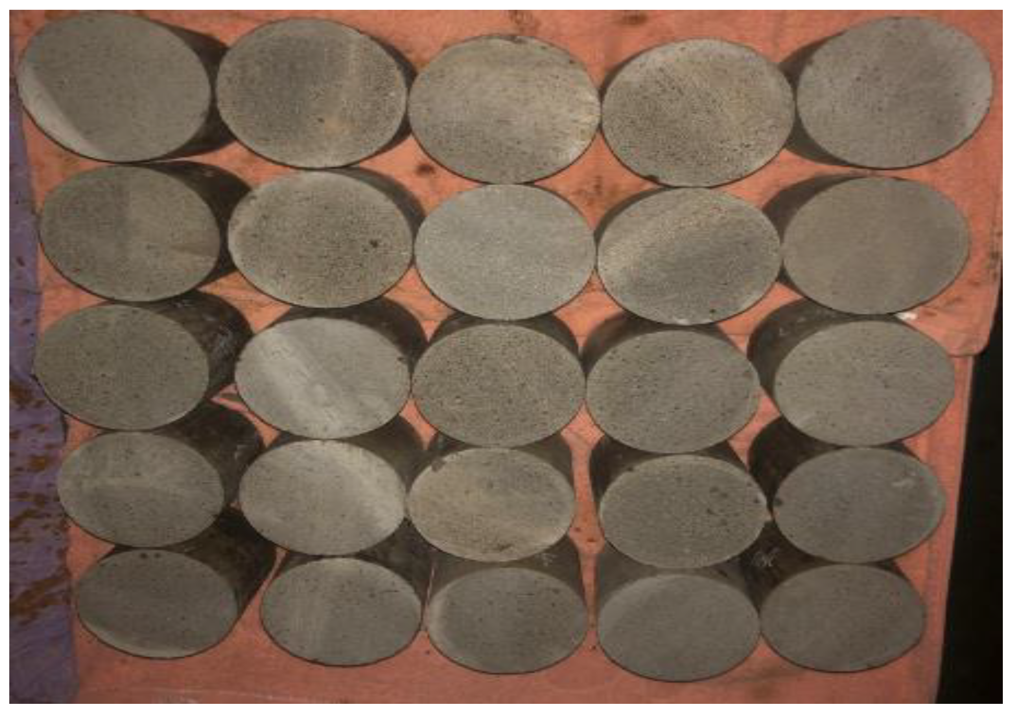
Figure 1. Polished CA mortar specimens.
Applsci 10 02860 g001
Figure 2. The uniaxial compressive test machine and control system for CA mortar: (a) MTS322-T type machine; (b) The closed-loop control system; (c) The setup of extensometer.
Applsci 10 02860 g002
Figure 3. The monotonic compression test for CA mortar: (a) The monotonic compression test; (b) Typical failure mode for CA mortar.
Applsci 10 02860 g003
Figure 4. Secant modulus of CA mortar specimens: (a) secant modulus; (b) mean and STD. of secant modulus; (c) Mean ± STD. of secant modulus.
Applsci 10 02860 g004aApplsci 10 02860 g004b
Figure 5. Complete stress–strain curve of CA mortar: (a) Stress–strain curves of CA mortar specimens; (b) Mean and standard deviation for stress–strain curves; (c) Mean ±   STD . for stress–strain curves.
Applsci 10 02860 g005
Figure 6. Schematic diagram of dividing model of strain energy density.
Applsci 10 02860 g006
Figure 7. Total input strain energy of CA mortar specimens: (a) Total input strain energy of CA mortar specimens; (b) Mean and STD of total input strain energy; (c) Mean ± STD of total input energy.
Applsci 10 02860 g007aApplsci 10 02860 g007b
Figure 8. Elastic strain energy of CA mortar specimens: (a) Elastic strain energy of specimens; (b) Mean and STD for elastic strain energy; (c) Mean ± STD for elastic strain energy.
Applsci 10 02860 g008
Figure 9. Dissipated strain energy of CA mortar specimens: (a) Dissipated strain energy of specimens; (b) Mean and STD. for dissipated strain energy; (c) Mean ± STD. for dissipated strain energy.
Applsci 10 02860 g009
Figure 10. The damage variable d of CA mortar specimens: (a) Damage variable d of specimens; (b) Mean and STD. of damage variable d; (c) Mean ± STD. of damage variable d.
Applsci 10 02860 g010aApplsci 10 02860 g010b
Figure 11. Comparison between experimental and theoretical curves for damage variable d: (a) Mean curve of d; (b) STD. curve of d.
Applsci 10 02860 g011
Figure 12. Comparison between experimental and theoretical stress–strain curves for CA mortar: (a) Mean stress–strain curve; (b) STD. of stress–strain curve.
Applsci 10 02860 g012aApplsci 10 02860 g012b
Figure 13. Comparison between experimental (Fu et al., 2014) and theoretical curves: (a) Strain rate at 0.0033 / m s 1 ; (b) Strain rate at 0.17 / m s 1 ; (c) Strain rate at 1.7 / m s 1 .
Applsci 10 02860 g013aApplsci 10 02860 g013b
Figure 14. Stochastic probability density of micro-damage thresholds of CA mortar under compression: (a) 12 CA mortar specimens; (b) The mean curve.
Applsci 10 02860 g014
Figure 15. Fitting of the probability density for the thresholds: (a) Lognormal distribution; (b) Weibull distribution; (c) Gauss distribution.
Applsci 10 02860 g015aApplsci 10 02860 g015b
Figure 16. Comparisons of the mean constitutive relationships among China Railway Track System (CRTS) CRTS II CA mortar, CRTS I CA mortar, and concrete under compression in terms of: (a) σ - ε curve; (b) σ - ε / ε c r i t i c a l curve; (c) σ / σ c r i t i c a l - ε / ε c r i t i c a l curve.
Applsci 10 02860 g016
Figure 17. Comparisons of the mean constitutive relationships among CRTS II CA mortar, CRTS I CA mortar, and concrete under compression in terms of: (a) d - ε curve; (b) d - ε / ε c r i t i c a l curve.
Applsci 10 02860 g017
Figure 18. Comparisons of the mean constitutive relationships among CRTS II CA mortar, CRTS I CA mortar, and concrete under compression in terms of: (a) Probability density— ε curve; (b) Probability density— ε / ε c r i t i c a l curve.
Applsci 10 02860 g018
Table 1. Physical properties of emulsified asphalt.
TypeSolid Content
(%)
Engler Viscosity (25 °C)Sieve Residue (1.18 mm) Storage Stability
(25 °C)
Evaporation Residues Penetration
(25 °C)/0.1 mm
Evaporation Residues Ductility
(25 °C) (cm)
1d5d
Anionic605.60.005%0.321.9481104
Table 2. Physical properties of cement.
Specific Surface Area (m2 kg−1)Loss on Ignition (%)Compressive Strength on 3 d and 28 d (MPa)Volume StabilityFlexural Strength on 3 d and 28 d (MPa)
3161.833.3 and 61.9Up to standard5.9 and 8.5
Table 3. Physical properties of pelletized sand.
Apparent Density (g/cm3)Moisture Content (%)Water Absorption Rate (%)Clay Content (%)Mud Content (%)Ruggedness (%)Organic Matter (Colorimetric Method)Chloride Content (%)
2.640.040.4002.0Up to standard0
Table 4. Main composition of aluminum powder.
ComponentAlFeSiCuH2OOther
Content (%)99.800.0760.0460.00190.0150.0611
Table 5. Mix proportion of cement emulsified asphalt (CA) mortar.
ComponentCementSandEmulsified AsphaltWater Reducing AdmixtureThickening AgentAluminate PowderAntifoaming AgentWater
Mix proportion (g/L)60690930312.131.210.055100
Table 6. Strengths of CA specimens.
Specimen No.Strength (MPa)Critical Strain (mm/mm)
115.650.0057
214.960.0064
316.700.0052
415.020.0051
515.760.0065
614.090.0075
715.300.0075
817.650.0073
916.110.0057
1015.910.0061
1114.440.0077
1215.130.0068
Mean15.230.0064
STD.1.830.0037
Table 7. Young’s Modulus of the 12 specimens.
Specimen No.Young’s Modulus (MPa)
14100.23
23316.96
34135.15
44239.79
53365.67
62477.80
72761.34
83186.02
93579.87
103799.22
112350.86
123001.41
Mean3359.53
STD611.00
Table 8. Identification results of parameters of mean of the damage variable μ d ( ε ) .
A 1 A 2 ε 0 p
−0.0130.9390.00813.2578
Table 9. Identification results of parameters of standard variation (STD) of the damage variable STD d ( ε ) .
A 3 A 4 w
0.121250.008140.00393
Table 10. Identification results of parameters of STD. of the stress–strain curve STD σ ( ε ) .
b 0 b 1 b 2
0.0010.23742.592