1. Introduction
Mechanical face seals are widely used for sealing rotating shafts. The working principle of mechanical face seals is that a pair of end faces slide perpendicular to the axis and function under the action of fluid pressure and compensating forces. An auxiliary seal, for example an O-ring seal, is used to prevent the leakage of the medium. Mechanical face seals are found in many devices with rotating parts, such as pumps, blowers, mixers, and other specific equipment [
1,
2,
3]. In this study, a mechanical face seal of an automotive cooling water pump is investigated, with a particular focus on friction instabilities [
4,
5].
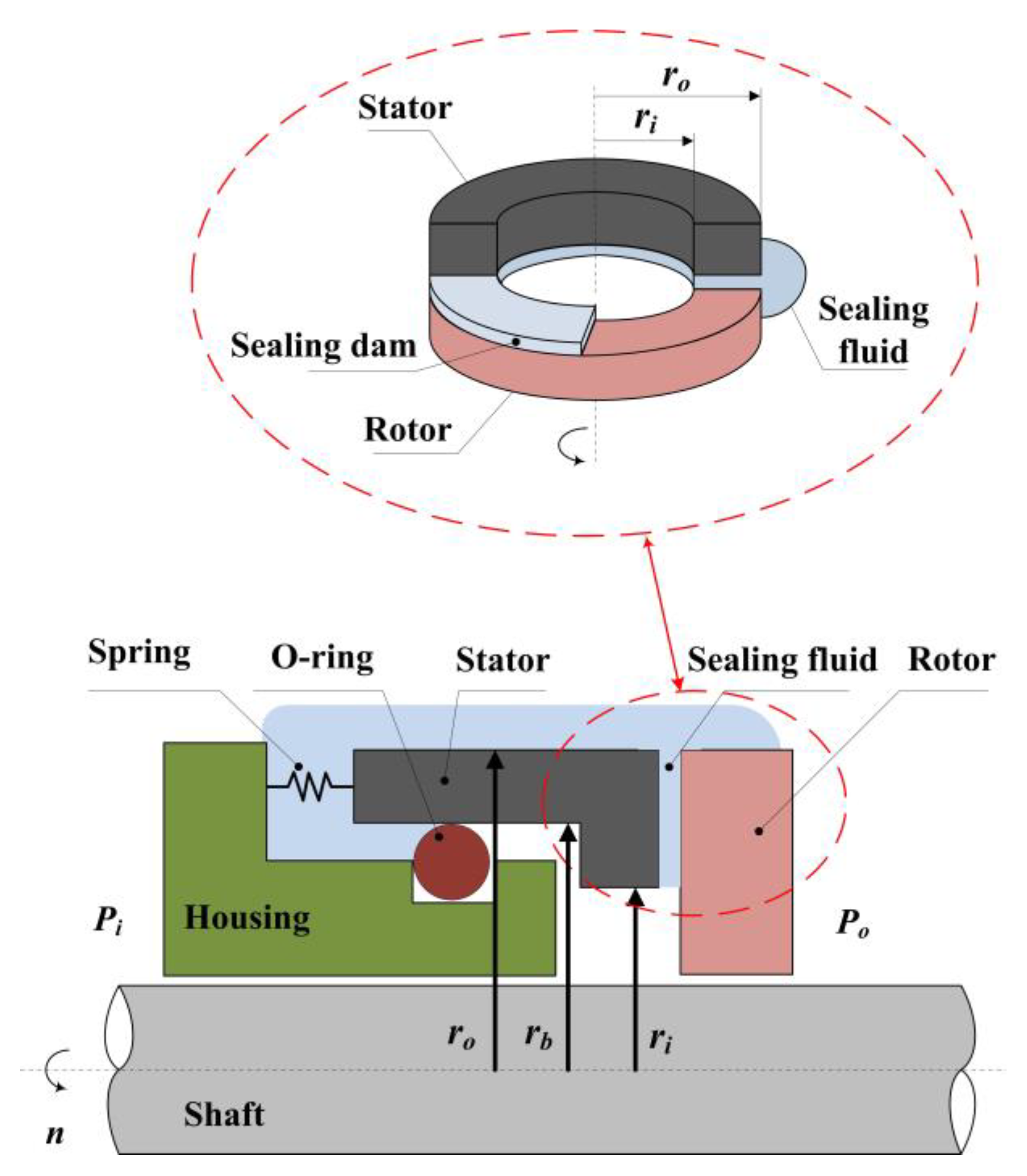
The primary components of a face seal are two rings, i.e., the stator and the rotor, as shown in
Figure 1. The mechanical seal changes the axial seal, which leaks easily, into an end face seal, which does not leak easily. Therefore, the contact between the stator and the rotor is the key in determining the performance of a mechanical seal [
6].
Wear between mechanical seals is inevitable; therefore, it is crucial to investigate the influence of the lubrication conditions between the mating surfaces on the wear, especially when friction instabilities occur. Friction instabilities of mechanical seals result in the stick-slip phenomenon, which is caused by fluctuations in the friction moment when an intermittent relative motion occurs between the mating surfaces. Stick-slip is usually confined to seals driven by a mono-spring. In general, mechanical seals have an anti-rotation pin to avoid stick-slip. Many authors have investigated the friction instability of mechanical seals, e.g., Ibrahim [
7,
8] and Klein [
9]. It was reported (e.g., Leine et al. [
10], Van De Velde, and De Baets [
11]) and observed in experimental tests that friction instabilities (mainly stick-slip) occurred during shaft deceleration and at low speeds. Paliwal et al. [
12] found that during the stick-slip process, asperity interactions occurred.
Lubrication reduces friction and wear and generates heat, but leakage has to be considered [
13]. The mechanical face seal may work in elastohydrodynamic lubrication, mixed lubrication, or boundary lubrication. In fluid lubrication, almost no contact occurs, the friction and wear are low, and almost all of the friction is viscous. Under mixed lubrication conditions, part of the load is borne by mechanical contact, which is the most common working condition of the seal. Therefore, the focus should be on friction and wear in this case. In the case of boundary lubrication, mechanical contact is the most important factor, and excessive mechanical contact between the two seal faces leads to high wear rates.
Although considerable research has been devoted to friction and wear in stable operating conditions, few studies have focused on wear under friction instability conditions. The model proposed by Valigi et al. [
4] does not consider the case of non-Gaussian surfaces, the effect of heat transfer, and the wear under friction instability conditions. Ayadi et al. [
14] analyzed seal lubrication and wear using experimental and numerical methods and found that surface roughness had a significant influence on the lubrication condition. Brunetière and Tournerie [
15] examined the effect of the geometrical aspect of the texture on the lubrication regime and established a relationship between texture density and friction. Nogueira et al. [
16] showed that during the running-in stage, the surface profiles changed significantly as a result of the smoothing of the asperities due to plastic deformation. Adjemout et al. [
17] showed that the surface texture of mechanical seals reduces friction, as well as leakage and wear. Minet et al. [
18] developed a numerical flow model of mixed lubrication in mechanical face seals. The model considered the cavitation effects and the Hertzian asperity contact.
The influence of wear on seals has attracted widespread attention among researchers. Shen et al. [
19] investigated the friction and wear characteristics of nitrile butadiene rubber (NBR) in two-body abrasion tests with different sizes of abrasives and showed that the size of the abrasive had a significant effect on the wear. The wear of a device with pin-pivot oscillating contact was investigated by Mukras et al. [
20]. Peng [
21] discussed the development of a mixed lubrication model using the multiple-grid method for a reciprocating rod seal. Salib et al. [
22] presented a new approach for adhesive wear modeling based on physical principles with no need for an empirical wear coefficient. The authors presented an empirical expression for predicting the wear coefficient. Li et al. [
23] used an iterative wear prediction method to change the geometric structure of the contact interface.
Wear is one of the critical factors affecting the life of mechanical seals. In this paper, based on the two degrees of freedom dynamic model of Valigi et al. [
4], a numerical wear simulation method that considers asperity interaction (non-Gaussian surfaces), heat transfer, and macro-scale dynamic parameters is presented. The effect of friction instabilities on the mechanical seals is described by a mass-spring-damping system. A detailed comprehensive model of a mechanical seal is presented, and a theoretical analysis and simulations are conducted. The wear distance rate is used to describe the axial motion, and the wear time rate is used to describe the circumferential rotation. The influences of the damping coefficient, torsional damping coefficient, axial stiffness, and torsional stiffness on the wear of the mechanical face seal under friction instability conditions are analyzed.
2. Mathematical Model of Mechanical Face Seals under Friction Instability Conditions
The schematic of the mechanical face seal is shown in
Figure 1. It was presented previously in [
4]. The stator is flexibly mounted to the housing via two elastic parts: a radial support spring and a viscoelastic secondary O-ring seal. The spring provides the closing force to the stator. The rotor rotates with the shaft. The inner and outer radii are denoted as
ri and
ro, respectively, and
rb is the balance radius. The sealing fluid pressure and atmospheric pressure are
Po and
Pi, respectively. Thus, the area of interest is a small radial band ranging from the outer radius
ro to the inner radius
ri, as shown in
Figure 1.
2.1. Fluid Mechanics Analysis
The fluid pressure p was evaluated by a tribological model of the mechanical seal based on the Reynolds lubrication theory. The output of the model showed that the fluid pressure occurred at the sealing interface.
As shown in
Figure 1, a sealing dam is formed between the rotor surface and the stator surface. The fluid film not only lubricates the interface surface and reduces friction and wear but also supports the parallel mating surfaces through a hydrodynamic effect. For an incompressible lubricant and considering the flow factors introduced by Patir and Cheng [
24], the average Reynolds equation for smooth surfaces [
25] is:
where
r is the radial direction,
α is the angular coordinate,
μ is the dynamic viscosity of the lubricant, ω = ∂
α/∂
t is the relative angular speed,
hn is the nominal film thickness, and
p is the mean hydrodynamic pressure.
Due to the axisymmetric configuration, ∂
p/∂
α = 0 and ∂
hn/∂
α = 0. Installation misalignment and cavitation are neglected. The seal operates between the mixed and boundary lubrication regimes, and the asperities interact so that the squeeze term ∂
hn/∂t can be neglected [
4] in the assessment of the fluid pressure. Thus, Equation (1) can be simplified as:
Equation (2) is then integrated to obtain the fluid pressure
pr.
Figure 2 shows the tapered film. The shape of the fluid film as a function of
r is expressed as follows:
where
n represents the slope, and
h1n indicates the height of the minimum gap located at the inner radius.
2.2. Mechanics Analysis of the Asperity Contact
If boundary lubrication and mixed lubrication conditions are present, asperity contact will occur, and the influence of the asperity contact pressure on the mechanical face seals cannot be neglected. Greenwood and Williamson proposed a model (G-W model) to calculate the asperity contact pressure [
26]. In the G-W contact model, the contact between two rough surfaces is reduced to a contact between a smooth rigid surface and a rough surface. Independent Hertz contact is assumed to occur, as shown in
Figure 3. It is assumed that the asperities have spherical summits, with a constant radius
Re. Furthermore, the asperity deformation is assumed to be a pure elastic deformation. According to the G-W model, the asperity contact pressure
pac is defined as:
where
φ(z) is the probability density function of the surface height distribution,
(z,
t) is the average value of the film thickness,
ηe is the equivalent surface density of the asperities,
Wa is the total asperity contact load,
An is the nominal contact area, and
Ee is the equivalent elastic modulus. The surface equivalent roughness
σe is defined as the root mean square roughness of the heights of the stator and rotor [
27].
However, the height distribution of the sealing surface cannot be approximated as a Gaussian distribution [
28]. The surfaces are non-Gaussian because of the asperity contact and the running-in of the seals. Typically, the Johnson transformation is used for the transformation between Gaussian and non-Gaussian distributed series [
29]. The four most important parameters of the Johnson transformation system (
γ,
ε,
λ, and
δ) can be obtained based on the first four moments, i.e., the mean, variance, skewness, and kurtosis of the non-Gaussian series. The frequency curve of the Johnson transformation system has three forms, namely: lognormal, unbounded, and bounded. After selecting the appropriate form of the frequency curve according to the Johnson transformation, the Johnson series
Zn-G is obtained from the transformation as:
where Z
G is the Gaussian distributed series, and Z
n-G is the non-Gaussian distributed series, and:
Therefore, the height distribution of the sealing surface, i.e., the non-Gaussian distributed surface, can be transformed from a Gaussian distributed surface with a specific skewness and kurtosis using the Johnson transformation. The Gaussian surfaces have a skewness coefficient of zero, indicating that the material is symmetrically distributed above and below the mean plane. The kurtosis coefficient of the Gaussian surface is three. This is not the case for mechanical seal faces, as demonstrated in [
27].
Mechanical seals are assumed to operate in laminar flow and without a phase change. Lebeck [
30] suggested the compressive yield stress
SC as a plausible value for the mechanical contact pressure
pc. The contact portion
bm of the mechanical seal can be estimated by a non-Gaussian cumulative distribution function:
The interfacial contact pressure is expressed as [
4]:
Thus, the asperity contact load
Fc is given as:
The first contact between the smooth rotor and rough stator occurs at the highest asperity point. The contact loads are weak, and the rings are made of brittle elastic materials; therefore, they do not exhibit plastic deformation [
31].
2.3. Dynamic Analysis of the Mechanical Face Seal
The dynamic model is shown in
Figure 4. This model can describe the friction instabilities, such as stick-slip, occurring in mechanical face seals. The model has two degrees of freedom: the axial motion
h1n and the circumferential rotation
θ around the seal’s axis of the stator assembly.
In the model proposed by Valigi et al. [
4], the mass
m and the moment of inertia
J include the spring, the mating ring, and its shell. The mass
m is connected to the housing by a spring with axial stiffness
K, torsional stiffness
Kt, axial damping
C, and torsional damping
Ct.
The dynamic characteristics of the mechanical seals are defined by the following equations:
The axial opening force is calculated by the total interfacial pressure P. As already mentioned, P is the sum of pc and pf, according to Equations (8) and (2), respectively. The axial force is calculated according to the given value h1, and an iterative process is used to solve the equation. The hydrostatic pressure Fp is the partial closing force .
The total axial force F(h1n) includes the asperity contact load and fluid pressure. The total torque consists of Mb and Ml. Mb represents the friction torque acting on the seal under boundary lubrication conditions. Ml is the viscous torque acting under full lubrication.
The friction coefficient
f(
ω) is defined in Equation [
4]:
where
is the mean peripheral speed of the seal,
is the normal probability density function of
,
is the mean value,
is the standard deviation of
, and
fd and
fs are the dynamic and static friction coefficients, respectively.
The relative angular speed ω between the matching surfaces is given by , where Ω(t) is the shaft’s angular speed and is the angular vibration of the stator.
2.4. Thermal Analysis
Heat is generated during the operation due to asperity friction and viscous shear stress. Consequently, a thermal approach is used to calculate the thermomechanical parameters [
32]. The heat flux generated in the contact area is computed from the contact friction torque and viscous friction torque of the asperities:
The heat generation rate
qr is determined by the viscous shear
qv and the frictional contact of the asperity
qf per unit area in the radial direction
r:
where
ω is the relative angular speed between the surfaces,
μ is the dynamic viscosity of the fluid film, and
pc is the interfacial contact pressure.
Regarding heat transfer, due to the symmetrical geometry of the mechanical seal, the seal interface is the only heat source. Heat transfer occurs in the radial direction and the direction of z. The governing equation of the heat transfer in a mechanical face seal is [
32]:
where
T represents the temperature of the sealing fluid,
t represents the time,
α represents the thermal diffusivity,
k represents the thermal conductivity, and
ω is the angular velocity of rotation. The temperature affects the fluid viscosity. The change in the fluid viscosity with the temperature is described by an exponential equation [
33]:
where
Ta is the average temperature of the sealing zone fluid. Since the seal rings in this study are very narrow, it is assumed that the average temperature of the fluid is:
2.5. Wear Model
In this work, the Archard wear model is used to calculate the local wear rate [
34]:
where
V is the volume loss,
L is the sliding distance,
KW is the dimensionless wear coefficient,
H is the hardness of the stator, and
FW is the normal force. Because the rotor is much harder than the stator, it is assumed that wear only occurs on the stator surface. The wear modulus
kw is defined as
KW/H; therefore, the wear model is rewritten as:
Wear is primarily caused by the asperity contact; therefore,
FW equals
Fc, and the wear depth
hw is defined as:
Typically, the wear modulus
kw is determined experimentally for a given lubrication condition. When the shaft of the mechanical face seal is rotating, the lubrication conditions change as the operating conditions change. Therefore, the modified Archard wear equation is used [
35]. Scaling factors are introduced to characterize the lubrication conditions. The wear modulus and Archard wear equation are modified based on the wear modulus under dry conditions.
According to the previous description, the interfacial pressure
P can be expressed as the sum of the asperity contact load
Pc and the hydrodynamic load
Pf:
The scaling factors
γ1 and
γ2 are introduced to express the load-sharing ratio of the asperity contact load and the hydrodynamic load, respectively. The scaling factors are defined as:
The sum of
γ1 and
γ2 equals 1. It is worth noting that time-varying lubrication models need to be considered. Therefore, the time-averaged asperity contact load and time-averaged hydrodynamic load are used to calculate the scaling factors:
The time-averaged hydrodynamic load
Pf_avg is defined as:
where
. The time-averaged asperity contact load
Pc_avg is defined as:
where
,
tu is the time span of the simulation,
Si is the seal interface area,
, and
.
Since the wear volume is only related to the asperity contact load, the scaling factor for the asperity contact is used in the Archard wear equation. The modified wear modulus
km is defined as
kwγ1. Hence, according to the modified Archard wear equation, the wear depth
hw is defined as:
The derivative of the wear depth with respect to time is defined as the wear time rate
kt, and the derivative of the wear depth with respect to the sliding distance is defined as the wear distance rate
ks. In most cases, the modified wear modulus is assumed to be constant during the iteration cycle. Therefore, the wear time rate and wear distance rate are defined as:
3. Numerical Algorithm
The analysis of the wear of the mechanical face seal based on the proposed mathematical model is performed using the numerical algorithm described in the flowchart in
Figure 5.
In the proposed mathematical model, the strong couplings among fluid mechanics, asperity contact mechanics, and thermomechanical effects are considered. Hence, an iterative calculation program was developed to deal with this coupling relationship. The Reynolds equation was solved by the finite difference method, and the pressure of the tapered film was obtained. The Newmark-β method was used to solve Equations (10) and (11). The fluid mechanics, asperity contact mechanics, and thermomechanics were recomputed until the liquid film thickness and average temperature exhibited convergence. The algorithm cycle begins with the initialization of the given total axial force F and total moment M. With the decrease in the shaft angular speed, at a new time instant, a new force F and moment M are obtained. The new force F and moment M are then used in the model, and the cycle starts again.
In the modified Archard wear model, the total normal pressure is calculated according to the asperity contact and fluid analysis. The modified Archard equation is used to calculate the wear of the mechanical face seal, which is then used to obtain the wear time rate and wear distance rate.
4. Validation of the Proposed Method
The simulation results and experimental results presented in Ref. [
4,
5] are used to verify the validity of the proposed mathematical model. The parameter values used in Ref. [
4,
5] are listed in
Table 1.
The simulation is performed by decreasing the shaft’s angular speed
Ω(t), which is shown in
Figure 6a. The angular vibration
θ(t) of the stator and angular vibration speed
of the stator are shown in
Figure 6b,c, respectively. The simulation results of the total torque are shown in
Figure 6d. It is observed that the simulation results are in good agreement with those in Ref. [
4,
5].
The torsional damping ratio is defined as , and the axial damping ratio is defined as . During shaft deceleration, the friction coefficient changes, causing the damping ratio of the dynamic system to change from positive to negative. Thus, when instability occurs, the stator begins to oscillate.
Considering the effects of the lubricated conditions, the wear modulus
kw was set as 0.35 × 10
−6 mm
3/N∙m; the value was obtained from wear tests [
36]. This wear modulus is an average value, measured in the boundary conditions regime. If the relative angular speed
ω between the matching surfaces is constant at 100 rad/s, the shaft does not decelerate. The stator profile after the operation is obtained using Equation (18); the result is shown in
Figure 7a, and the worn area is shown in
Figure 7b. The stator profiles demonstrate that wear has occurred near the inner radius; this result is in agreement with the result obtained by Ayadi [
14].
These results validate the proposed method. However, the difference between Gaussian and non-Gaussian surfaces and the change in viscosity with the temperature of the film need to be further discussed. In addition, the influence of the dynamic parameters, such as the axial stiffness, axial damping, torsional stiffness, and torsional damping on the seal is also analyzed.
5. Simulation Results and Discussion
The proposed wear simulation method for the mechanical face seal is used to analyze the height distribution of the sealing surface and the dynamic parameters on the seal wear. The values of the main simulation parameters are shown in
Table 1.
5.1. Influence of Gaussian and Non-Gaussian Surfaces on the Wear
5.1.1. The Contact Pressure of Gaussian and Non-Gaussian Surfaces
According to the given surface roughness, the distribution of the contact pressure on the sealing surface is determined using Equation (8). Thus, the contact pressure
pc of the sealing zone is simulated for different heights of the minimum gap. The radial distribution of the contact pressure
pc of the Gaussian surfaces at different heights of the minimum gap is shown in
Figure 8a for the equivalent roughness of the sealing surface of
σe = 0.152 × 10
−6 m;
h1n indicates the height of the minimum gap located at the inner radius. The inner diameter of the seal ring is more prone to contact pressure than the outer diameter because of the tapered film. The distribution of the contact pressure
pc in the seal ring is shown in
Figure 8b (
h1n = 0.152 µm). It is evident that the pressure is higher on the inside than on the outside of the seal ring.
If the probability density function of the surface height distribution
ϕ(z) is non-Gaussian, the distribution of the contact pressure
pc will change. The main parameters of the seals are presented in
Table 2 [
27]. The skewness
Sk and kurtosis
Ku of the three groups of sealing parameters are different, and the equivalent roughness of the sealing surface
σe is the same. The probability density functions of the surface height for the three cases are shown in
Figure 9.
The contact pressure
pc of seal 1, seal 2, and seal 3 is shown in
Figure 10a,b,c, respectively. The contact pressure decreases with the height of the minimum gap
h1n. In
Figure 10d, the contact pressure is shown for seal 1, seal 2, and seal 3 with
h1n = 0.152 µm; the contact pressure
pc decreases from 7.0 × 10
7 Pa to 1.5 × 10
7 P. Compared with the Gaussian surfaces or the corresponding content in [
4], the contact pressure generated by non-Gaussian surfaces at the inner diameter is larger, but decreases faster along the radial direction.
The results indicate that the contact pressure
pc decreases with the decrease in the skewness coefficient and kurtosis coefficient of the sealing surface. According to Equation (8) and
Figure 9, for a given
h1n, the contact portion
bm decreases with the decrease in the skewness coefficient and kurtosis coefficient. Thus, the contact pressure
pc decreases.
5.1.2. Analysis of the Wear Distance Rate
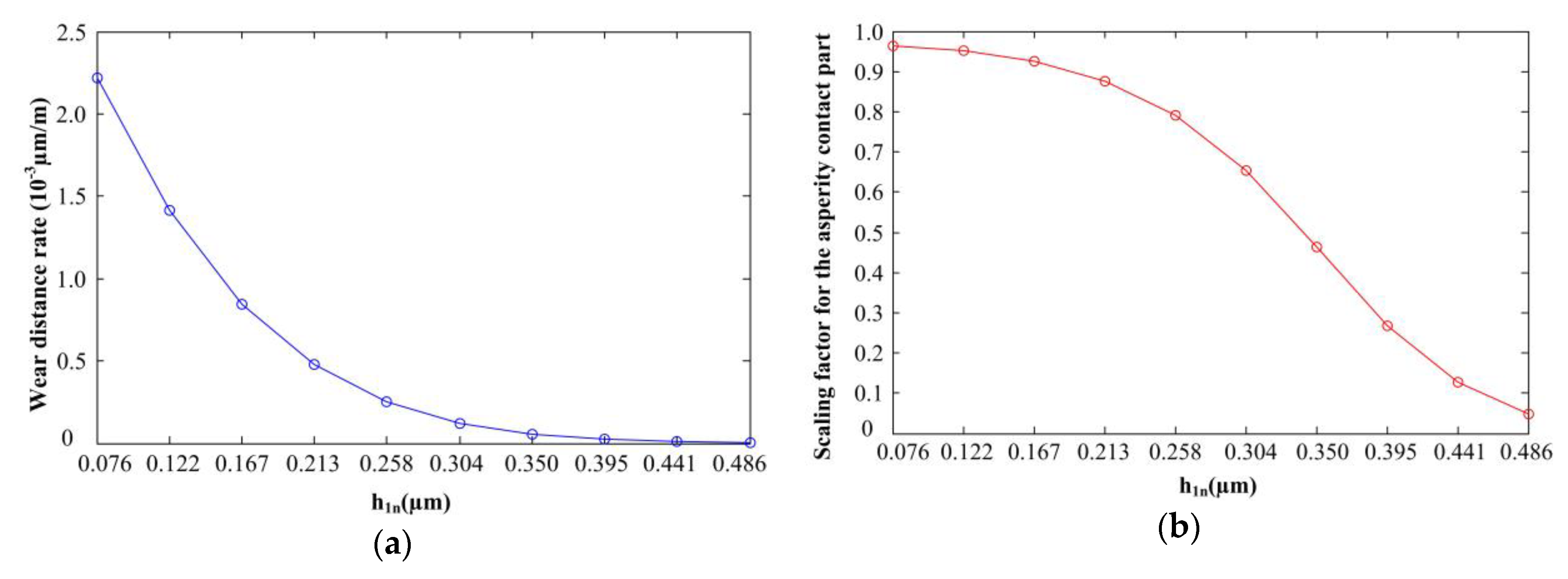
Equation (30) indicates that the wear distance rate is related to the time-averaged total normal load, which is ultimately determined by the thickness of the tapered film. Here, the wear modulus kw is 0.35 × 10⁻⁶ mm3/N∙m, and it is assumed that the shaft is rotating at a constant speed. The friction instabilities will be discussed below.
As shown in
Figure 11a, for the Gaussian surfaces, the wear distance rate decreases with the increase in the thickness of the tapered film
h1n. As
h1n increases from 0.076 µm to 0.486 µm, the wear distance rate decreases from 2.22 × 10
−3 µm/m to 0.03 × 10
−3 µm /m. The reason is shown in
Figure 11b; with the increase in the thickness of the tapered film
h1n, the average oil film thickness increases, which improves the lubrication of the sealing zone, and the contact pressure
pc decreases; therefore, the scaling factor for the asperity contact
γ1 decreases.
The wear distance rate of the non-Gaussian surfaces and the scaling factor for the asperity contact are shown in
Figure 12a,b, respectively. Compared with the Gaussian surfaces, the wear distance rate of the non-Gaussian surfaces is larger when
h1n is small, but the wear distance rate decreases rapidly. The reason is shown in
Figure 9, which depicts the probability density function of the surface height. For the same thickness of the tapered film, according to Equation (8), the cumulative distribution function value
bm of seal 1, seal 2, and seal 3 decreases; therefore, the interfacial contact pressure decreases. As shown in
Figure 12a, as
h1n increases from 0.076 µm to 0.486 µm, the wear distance rate decreases. For seal 1, seal 2, and seal 3, the wear distance rate is equal to zero when the values of
h1n are 0.304 µm, 0.258 µm, and 0.258 µm, respectively. In this case, there is no contact pressure. In
Figure 12b, as
h1n increases from 0.076 µm to 0.486 µm, the scaling factor for the asperity contact decreases rapidly to zero. For seal 1 and seal 2, the scaling factor is zero when the values of
h1n are 0.304 µm and 0.258 µm, respectively. For seal 3, the scaling factor is close to zero when
h1n is 0.258 µm.
5.2. Thermal Analysis
According to Equation (14), the heat generated during the operation of the mechanical seal consists of two parts, i.e., the viscous shear heat and the frictional heat due to the asperity contact, and the latter represents the larger proportion. The materials used in the rings are silicon carbide (SiC) and resin-impregnated carbon, and their thermal conductivity values are 130 W/m∙K and 10 W/m∙K, respectively [
37]. As shown in
Figure 13a, the red line represents the portion of the heat flux resulting from the asperity contact
qf, and the blue line represents the portion of the heat flux resulting from the viscous shear heat
qv; both heat fluxes decrease with an increase in
h1n. When
h1n is small,
qf is significantly larger than
qv, and when
h1n is large, the difference between the fluxes is not significant. The average temperature of the fluid during the steady-state operation of the shaft is 30 °C, that is, the shaft angular speed is 100 rad/s, as shown in
Figure 6a. The change in the average temperature for different
h1n values after shaft deceleration is shown in
Figure 13b. The average temperature of the fluid gradually decreases from 66.86 °C to 30.16 °C as
h1n increases from 0.076 µm to 0.486 µm; the reason is the decrease in
qf.
5.3. Wear Analysis
The probability density function of the surface height
ϕ(z) is non-Gaussian; the simulation parameters of the three seals are listed in
Table 2. The shaft deceleration is shown in
Figure 6a. The model has two degrees of freedom: the axial motion and the circumferential rotation. The primary influencing factors of the axial motion are the axial stiffness and axial damping, and the primary influencing factors of the circumferential rotation are the torsional stiffness and torsional damping. According to Equations (29) and (30), the wear distance rate is used to describe the axial motion, and the wear time rate is used to describe the circumferential rotation. At an initial axial stiffness of 48,000 N/m, the initial
h1n equals 0.192 µm.
5.3.1. Influence of the Axial Stiffness on the Seal Wear
The wear distance rate for different axial stiffness values is shown in
Figure 14a. At a low axial stiffness, the interfacial contact pressure is low; the fluid pressure plays an important role, and the wear is very small. As the axial stiffness increases,
h1n decreases, and the interfacial contact pressure increases; as a result, the wear increases. As the axial stiffness increases from 22,000 N/m to 60,000 N/m, the scaling factor for the asperity contact increases from 0 to 0.178 (
Figure 14b). Therefore, it is necessary to maintain the axial stiffness in a particular range to reduce wear.
5.3.2. Influence of Axial Damping on the Seal Wear
According to Equation (30), the wear depends on the interfacial pressure
P, which is determined by
h1n. Equation (10) indicates that the axial damping of the mass-spring-damping system does not change the value of the
h1n in the final steady-state but only changes the duration of the oscillation for the positive damping of the system. The thickness of the tapered film over time is shown in
Figure 15a,
Figure 15b, and
Figure 15c. The axial stiffness is 42,000 N/m, and the axial damping values
C are 2.0 N∙s/m, 3.0 N∙s/m, and 5.0 N∙s/m, respectively. The results show that the final value of
h1n is the same, but that the duration of the oscillation is different. Therefore, axial damping has no effect on the wear.
5.3.3. Influence of the Torsional Stiffness on the Seal Wear
During the deceleration of the shaft, the torsional stiffness
Kt increases from 3.0 N·m/rad to 8.0 N·m/rad; the wear time rate for different torsional stiffness values is shown in
Figure 16. As the torsional stiffness increases, the wear time rate decreases at different rates of decrease. The reason is that during shaft deceleration, the main influencing factor is torsional damping, and the influence of the torsional stiffness is relatively small.
5.3.4. Influence of Torsional Damping on the Seal Wear
During the deceleration of the shaft, the torsional damping
Ct increases from 5.0 × 10
−5 kg·m
2 to 55.0 × 10
−5 kg·m
2; the wear time rate for different torsional damping values is shown in
Figure 17. With the increase in torsional damping, the wear time rate decreases. The reason is that an increase in torsional damping reduces the oscillations of the stator. When the torsional damping is equal to 55.0 × 10
−5 kg·m
2, the stator does not oscillate during the shaft deceleration process. The relative angular speed
ω between the matching surfaces for different torsional damping values is shown in
Figure 18. The oscillation of the stator decreases with an increase in torsional damping.
6. Conclusions
In this study, mechanical face seals for automotive cooling water pumps were investigated. Friction instabilities will occur in mechanical face seals when the axle decelerates or operates at a low speed. We conducted a fluid mechanics analysis, asperity contact mechanics analysis, dynamic analysis, and thermal analysis and investigated the influence of the surface parameters and dynamic parameters, such as the axial stiffness and torsional stiffness, on the wear of the seal.
A comparison of the contact pressure of Gaussian and non-Gaussian surfaces indicated that non-Gaussian surfaces were more likely to generate high contact pressure; the contact pressure decreased with the decrease in the skewness coefficient and kurtosis coefficient of the sealing surface. The wear distance rate of non-Gaussian surfaces was larger than that of Gaussian surfaces when the thickness of the tapered film was small, but the wear distance rate decreased rapidly.
The heat generated in the mechanical seal consisted of two parts, that is, the viscous shear heat and the frictional heat due to the asperity contact; both decreased with an increase in the thickness of the tapered film. When the thickness of the tapered film was small, the frictional heat flux was significantly larger than the viscous shear heat flux, and when the thickness of the tapered film was large, the difference between the fluxes was not significant.
As the axial stiffness increased, the wear distance rate increased during shaft deceleration. Axial damping did not affect the wear and only changed the duration of the oscillation. The wear time rate was used to describe the circumferential rotation; as the torsional stiffness increased, the wear time rate decreased, but the effects were relatively small. Similarly, the wear time rate decreased with an increase in torsional damping; after torsional damping reached a certain value, the stator stopped oscillating.
The results of this work provide a foundation for engineers to design mechanical face seals for friction instability conditions. Suggestions for future work include the calibration of the relevant parameters using different tests to correlate the simulation results with experimental findings, the repeatability of this phenomena, as well as an analysis of the influence of changes in the contact conditions on the wear, the temperature distribution of the rings, and the degradation process of the mechanical face seal.


