Article

Design and Dynamics of Kinetic Launcher for Unmanned Aerial Vehicles

by
Mirosław Kondratiuk
* and
Leszek Ambroziak
Department of Robotics and Mechatronics, Mechanical Faculty, Bialystok University of Technology, Wiejska St. 45C, 15-351 Bialystok, Poland
*
Author to whom correspondence should be addressed.
Appl. Sci. 2020, 10(8), 2949; https://doi.org/10.3390/app10082949
Submission received: 30 March 2020 / Revised: 15 April 2020 / Accepted: 21 April 2020 / Published: 24 April 2020
(This article belongs to the Section Mechanical Engineering)

Abstract

:
Assisting in the starting procedure of Unmanned Aerial Vehicles (UAVs) is one of many very important areas of modern aviation research. Supported start-up saves fuel or electrical energy, increases operator safety and level of autonomy, extends the application area, and, in some applications, even enables the operator to shape the motion characteristics of the initial phase of a UAV’s flight. Currently used solutions, depending on an aircraft’s class, are based on the utilization of rubber, pneumatic or electromagnetic launchers. All of these launchers are used for the medium class of UAVs and all of them use the potential energy previously stored in stretched rubber, compressed air or electrical voltage. In this paper, authors propose the novel concept of a launcher powered through kinetic energy stored in a rotary wheel driven by an electric motor. Using the transmission systems of the drive and the controlled clutch and an electromagnetic brake, it is possible to precisely control the speed and acceleration of the launched object. Within the paper, the authors present and discuss the applied equations of dynamics, the results of a simulation that was carried out using the MATLAB/Simulink software and a conceptual CAD model of preliminary engineering solutions for the kinetic UAV launcher. The work is summarized in the conclusions section, which details the practical implementation of the device.

Graphical Abstract

1. Introduction

Many different types of devices are used nowadays in the starting procedures of Unmanned Aerial Vehicles (UAVs). The use of a UAV launcher can provide the following advantages:
  • energy savings (fuel, electricity);
  • compensation for insufficient on board power reserves;
  • enables the take-off of UAVs without chassis;
  • can be used when runway is limited or inaccessible (muddy terrain, high grass, stones, etc.);
  • increases the level of operator’s safety;
  • provides new possibilities for UAV design (location of wings and propulsion sources, chassis elimination);
  • ensures special start conditions (acceleration, velocity, initial angle of attack, etc.).
The most important argument among those mentioned above is operator safety. Aircraft with a mass less than 10 kg can be thrown by operators but that can expose them to injury since the wings or propellers sometimes have sharp edges. Another reason for using launchers is related to research concerning formation flight. A wide range of works within this field has been conducted for many years throughout the world [1,2,3] as well as in Poland [4]. Some concepts require small flying objects to be located in a predetermined time and in precisely defined positions [5,6]. This can be achieved by launching airplanes sequentially at certain speeds and at specified intervals. This task can be achieved through the use of launchers with controlled motion parameters. Numerous types of launchers are utilized depending on the class of a UAV [7] with rubber driven catapults being the most common in connection with small planes (up to 5 kg). Their design usually consists of a frame and a set of rubber ropes which act as the drive. However, for micro aerial vehicles (MAVs), for example, so-called “bungee” launchers constructed with only rubber elements without any frames are used. The size of a rubber launcher depends on the aircraft’s dimensions as well as its mass with the possibility to apply these types of catapults to UAVs weighing from a few to over a dozen kilograms [7,8]. Rubber launchers can have a modular structure and can be disassembled into smaller components making them easy to transport. Some very important disadvantages of these types of devices are their limited ability to control motion parameters and the relatively quick wear of their elastic elements which is the reason special systems are sometimes used to monitor the tension of their rubber drives. Work on the design and construction of rubber driven launchers is carried out, among others, at the Bialystok University of Technology (BUT) in Poland. Pneumatic launchers can be used for small and medium class of aircraft. In these types of catapults compressed air is utilized as the driving medium. Great energy stored through compressing air makes it possible to launch UAVs weighing several dozen or even hundreds of kilograms [7]. The construction of such devices requires the use of special carriage to which the airplane being launched can be attached during the starting phase. After UAV start it is necessary to initiate a controlled braking process of the carriage. In pneumatic launchers, maintaining motion parameters, both during the launching and the braking phase, can be quite complicated due to the system’s high inertial forces and thermodynamic properties [9]. Steam driven devices are also used in starting procedures, especially in respect to large flying objects. They are most commonly used on aircraft carriers to assist the launch of big manned aircraft and unmanned tactical airplanes weighing up to several dozen tons [7]. Thermal energy generated by the ship’s reactors is used to evaporate water into steam which is then used to power steam launchers. Rocket propulsion is also used to accelerate tactical objects such as the so-called “smart” missiles that are nothing more but flying unmanned aerial vehicles. These types of devices are most commonly used for military purposes. The need for motion control, repeatability of startup parameters, protection against overloads and operator safety has numerous researchers working, in Poland as well as abroad, on controlled launcher design. The investigation of electrically powered devices has been particularly popular and has been considered both in the past [10,11,12] as well today [13,14,15,16,17], even concerning for UAVs of a few hundred kilograms weight [18]. A prototype of a synchronous magnetic launcher for MAVs having a mass up to 2 kg has been developed at the BUT [8,19,20,21] with research into a similar prototype for aircraft weighing 10, 20 and 25 kg also initiated [22]. Today, the main technical problem associated with launchers for UAVs is the accumulation of energy. The use of solutions with high energy density is essential. Depending on the design, there are several solutions for storing energy: capacitors and batteries—in magnetic launchers, pressure tanks—in pneumatic and steam launchers, elastic parts—in rubber driven launchers, etc. A feature that is common to all of these solutions is the storage of energy in its potential form. However, it is possible to develop a launcher which can be powered by kinetic energy. The storing of kinetic energy through the utilization of rotating flywheels has been known for a long time. Their simple mechanical design ensure high reliability and durability while the transfer of torque from such a source is possible through the use of different forms of clutches [23]. Currently, active electromagnetic clutches and brakes provide some new possibilities for using stored rotational energy to power UAV launchers.

2. Kinetic Launcher Idea Description and Mathematical Model

In the paper we propose the use of kinetic energy stored in a rotating flywheel, which, after being converted through a system utilizing an active electromagnetic clutch and brake into linear motion, can be employed to launch a UAV. The system was designed for medium class of unmanned airplanes not exceeding a mass of 20 kg. A construction involving the use of stored rotational energy to launch medium-class UAVs was proposed. The name suggested for this type of catapult is the Kinetic Launcher (KL) for UAVs. The device consists of two subsystems: the rotating drive and the drive transmission with a synchronous toothed belt. The main components of the mechanism are presented in Figure 1.
The device needs a base consisting of a special frame on which all its components will be mounted. The drive transmission of the launcher requires the use of synchronous toothed belts making the conversion of the energy stored in the flywheel into kinetic energy of the launched object possible with minimal losses. The belts are mounted on driving gears (located at the base of the launcher frame) and on driven gears (in its top part). Torque control is possible through the utilization of an active electromagnetic clutch and brake subsystems which need to be closed in control system loops with feedback signals in the form of the launched object’s linear displacement, velocity or acceleration. Measurements can be made using an encoder sensor mounted on the driven wheels in the top part of the launcher frame. Naturally, the proposed device requires supports which will allow the setting of the required start angle as well as a carriage on which the launched object will be fastened. This carriage will move along linear tracks which are necessary to stabilize the motion of the launched UAV and minimize friction. The rotating drive part of the KL is composed of a shaft mounted flywheel, a DC motor with an asynchronous belt transmission used to drive the flywheel, driving gears attached to the shaft, an active electromagnetic clutch connecting the flywheel and the driving shafts, a fixed braking shaft and an active electromagnetic brake connecting the driving and the braking shafts. The rotating drive of the KL along with a list of its main components has been presented in Figure 2.

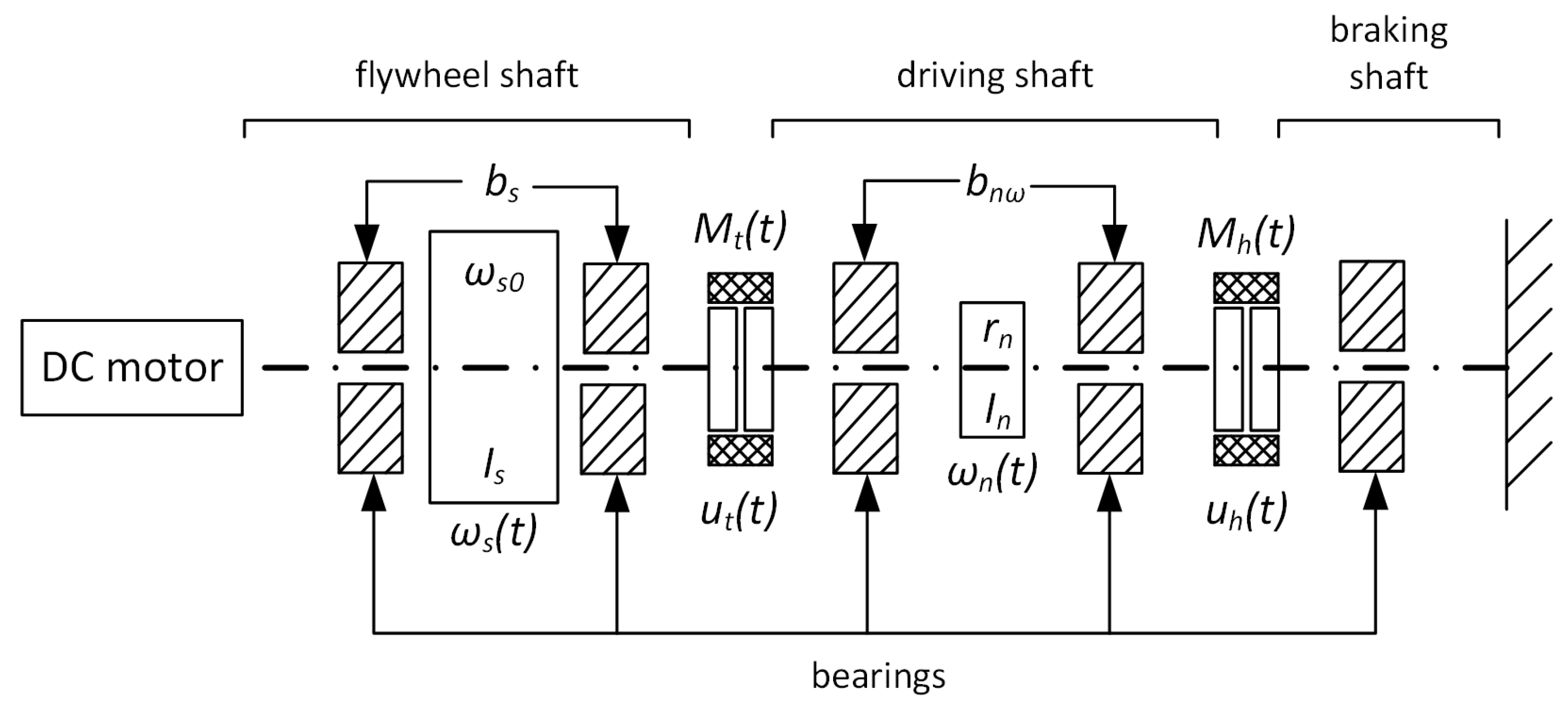
2.1. Structure of Kinetic Launcher

Figure 3 shows the parts of the kinetic launcher’s rotating drive and presents some crucial signals and parameters.
b s - flywheel damping rate, [Nm/rad/s];
ω s 0 - initial angular speed of the flywheel, [rad/s];
I s - flywheel moment of inertia, [kgm 2 ];
ω s (t)- angular speed of the flywheel, [rad/s];
M t (t)- driving torque transmitted by the clutch, [Nm];
u t (t)- electromagnetic clutch control signal, [dimensionless];
b n ω - damping rate of the rotating drive elements, [Nm/rad/s];
r n - radius of the drive wheels of the launcher, [m];
I n - total moment of inertia of the driving and driven wheels, [kgm 2 ];
ω n (t)- angular speed of the driving tooth wheels, [rad/s];
M h (t)- braking torque transmitted by the clutch, [Nm];
u h (t)- electromagnetic brake control signal, [dimensionless].
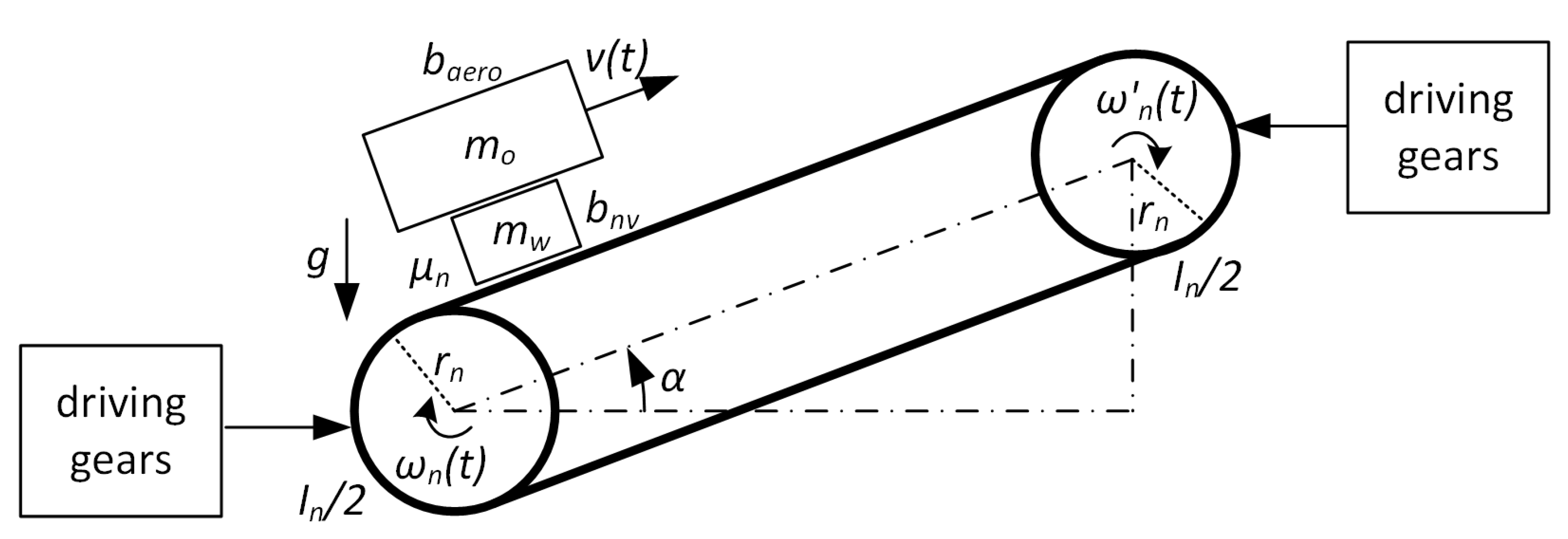
The damping of the rotational motion of the flywheel and the drive were considered in the model. The DC motor is necessary to put the flywheel into motion and bring it up to an appropriate speed. After that, the motor is idle and rotates freely together with the flywheel. In the construction of the device three shafts were proposed: the flywheel shaft, the driving shaft and the braking shaft. All shafts are mounted on bearings. Torque transmission between the shafts is achieved through an active electromagnetic clutch and a brake controlled using dimensionless u t (t) and u h (t) signals, respectively. On the side opposite the flywheel, the braking shaft is fixed to the launcher frame.
Figure 4 depicts the synchronous drive transmission subsystem.
g- gravitational acceleration, [m/s 2 ];
μ n - Coulomb friction coefficient, [dimensionless];
b a e r o - aerodynamic damping rate, [N/m/s];
m o - mass of UAV, [kg];
m w - mass of launcher cart, [kg];
v(t)- velocity of the UAV and launcher cart, [m/s];
b n v - damping rate of the linear motion, [N/m/s];
α - angle of launch, [rad];
ω n (t)- angular speed of the driven wheels, [rad/s].
In order to transmit motion from the driving gears to the driven gears we proposed using a pair of synchronous toothed belts. This is a well known textbook approach often used in these types of solutions [23]. The toothed belts have to display some level of resilience and elasticity since we are aware that they can significantly influence the behavior of the device. We have introduced the ω n ( t ) and ω n ( t ) signals which describe the angular speed of the launcher’s driving and driven gears, respectively. Nevertheless, if we take into account the relatively not-so-small total length and negligibly low flexibility of the belts, we can simply assume that: ω n ( t ) = ω n ( t ) . Thus, we are certain that v ( t ) = r n ω n ( t ) holds over the entire distance required to launch of UAV. In the model, we introduced two masses. One of them is connected with the launching carriage and other linearly moving parts while the second represents the UAV being launched. These masses strongly impact the dynamic behaviors of the system both in the starting as well as in the braking phase.

2.2. Mathematical Description

In the system described in the previous subsection we introduced the angular speed of the flywheel ω s ( t ) and the angular speed of the driving gears. These two variables are connected through the torque transmitted by the active electromagnetic clutch M t ( t ) . Thus, the dynamic equation involving viscous losses in the flywheel bearings can be expressed in the following way:
I s d ω s t d t = M t t b s ω s t
The dynamic equation of the driving mechanism is more complex. It involves the torque transmitted by the active electromagnetic clutch M t ( t ) , the braking torque caused by the active electromagnetic clutch M h ( t ) , viscous losses in the bearings of rotating parts ( b n ω ), viscous losses in the linear track ( b n v ), aerodynamic drag ( b a e r e o ), gravity (g) and Coulomb friction ( μ n ). The impact of the above mentioned parameters has been expressed using the following formula:
I n d ω n t d t = M t t M h t b n ω ω n t b n v r n 2 ω n t b a e r o r n 2 ω n t f s e p t r n 2 d ω n t d t + r n g sin α + μ n g r n cos α s i g n r n ω n t m w + m o f s e p t .
In order to describe how the UAV disengages from the launcher, we have introduced a launching carriage/UAV separation function f s e p ( t ) which can be expressed in the following manner:
f s e p t = 1 for x t x h 0 for x t > x h .
Parameter x h represents the linear distance where the braking phase starts. Assuming a lack of flexibility of the transmission toothed belt we can create equations for linear displacement x ( t ) , velocity v ( t ) and acceleration a ( t ) of the launcher carriage with the attached UAV [23].
x t = r n ω n t d t .
v t = r n ω n t .
a t = r n d ω n t d t .
The dynamics of the active electromagnetic clutch and the brake can simply be described as a standard R L circuit [23,24]. Equations involving time constants T t , T h and maximum torque capacities M t 0 , M h 0 are presented below:
T t d M t t d t + M t t = M t 0 u t t .
T h d M h t d t + M h t = M h 0 u h t .
Transmitted and braking torques can be controlled, respectively, by binary u t ( t ) and u h ( t ) signals. They can be generated as the output of the control algorithm with feedback implemented on a microcontroller. One of the simplest approaches to this is to use the x h parameter.
u t t = 1 for x t x h 0 for x t > x h .
u h t = 0 for x t x h 1 for x t > x h .

3. Simulations

Equations from Section 3.2 were implemented through the use of the MATLAB/Simulink software. Several simulations were conducted. Some model parameters were constant. Their values are presented in Table 1.
Damping and friction coefficients were changed in subsequent simulations. Distance x h was also modified. Its value directly determined the required length of the launcher.

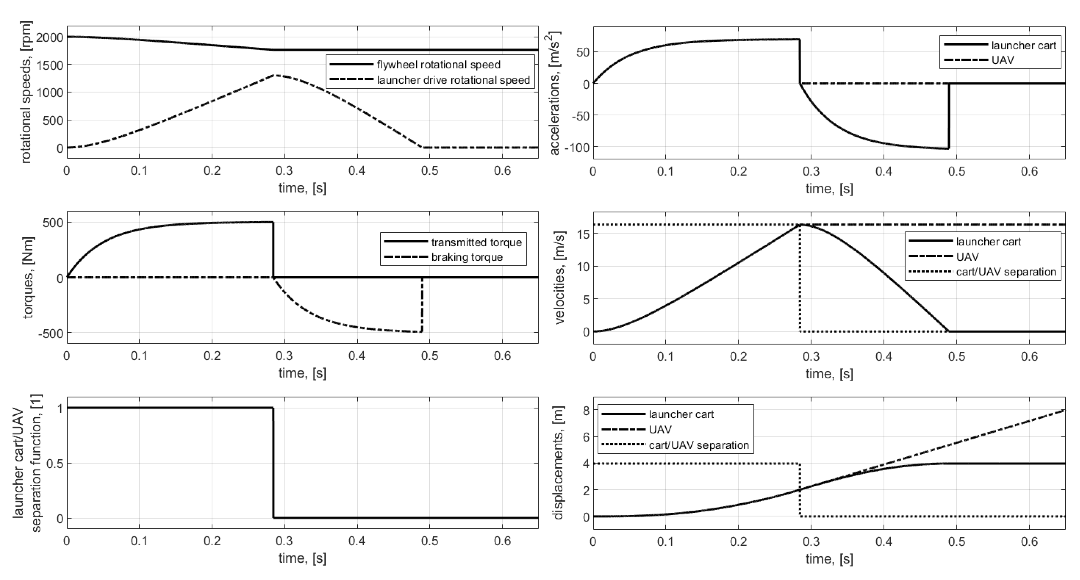
3.1. The 1st Simulation

In order to check if the proposed conception was correct, the first simulation was conducted without accounting for damping and friction. The x h value was arbitrarily set to 2 m. The results of that simulation are shown in Figure 5.
Simulation time was set to 0.65 s. The initial value of the angular speed ω s 0 = 210 rad/s presented in the Table 1, in accordance with Equation (11), corresponds to the rotational speed n s 0 = 2000 rpm.
ω n t = π · n s t 30 .
The flywheel’s mass moment of inertia was approximately calculated for a steel cylinder having a mass of approximately 150 kg, being 0.1 m thick and having a diameter of 0.25 m. Angular speed graphs showing the flywheel’s rotation ω s ( t ) and that of the driving gears ω n ( t ) have been depicted in Figure 5. According to the law of energy conservation, when torque is transmitted from the flywheel to the driving gears its angular speed drops. When the position of the launching carriage with the UAV attached is equal or greater than x h , the active electromagnetic clutch disengages initiating the braking phase. At this point, due to inertial forces, the UAV becomes detached from the launcher. The braking forces act only on mass mw. This explains why the absolute maximum values of transmitting and braking torques are equal and absolute maximum deceleration value is much higher than the acceleration value. We also proposed the use of an active electromagnetic brake in our kinetic launcher that causes the deceleration of the launching carriage which is clearly visible on the acceleration graph. Unfortunately, the inertial character of the active magnetic brake extends the braking distance. In the first simulation this was about 2 m putting the total length of the launcher at approximately 4 m. The application of some other technique for decelerating the launching carriage, such as mechanical bumpers or rubber catch ropes, can significantly decrease the total length of the kinetic launcher, even to the x h value. The application of some other technique for decelerating the launching carriage, such as mechanical bumpers or rubber catch ropes, can significantly decrease the total length of the kinetic launcher, even to 16 m/s.

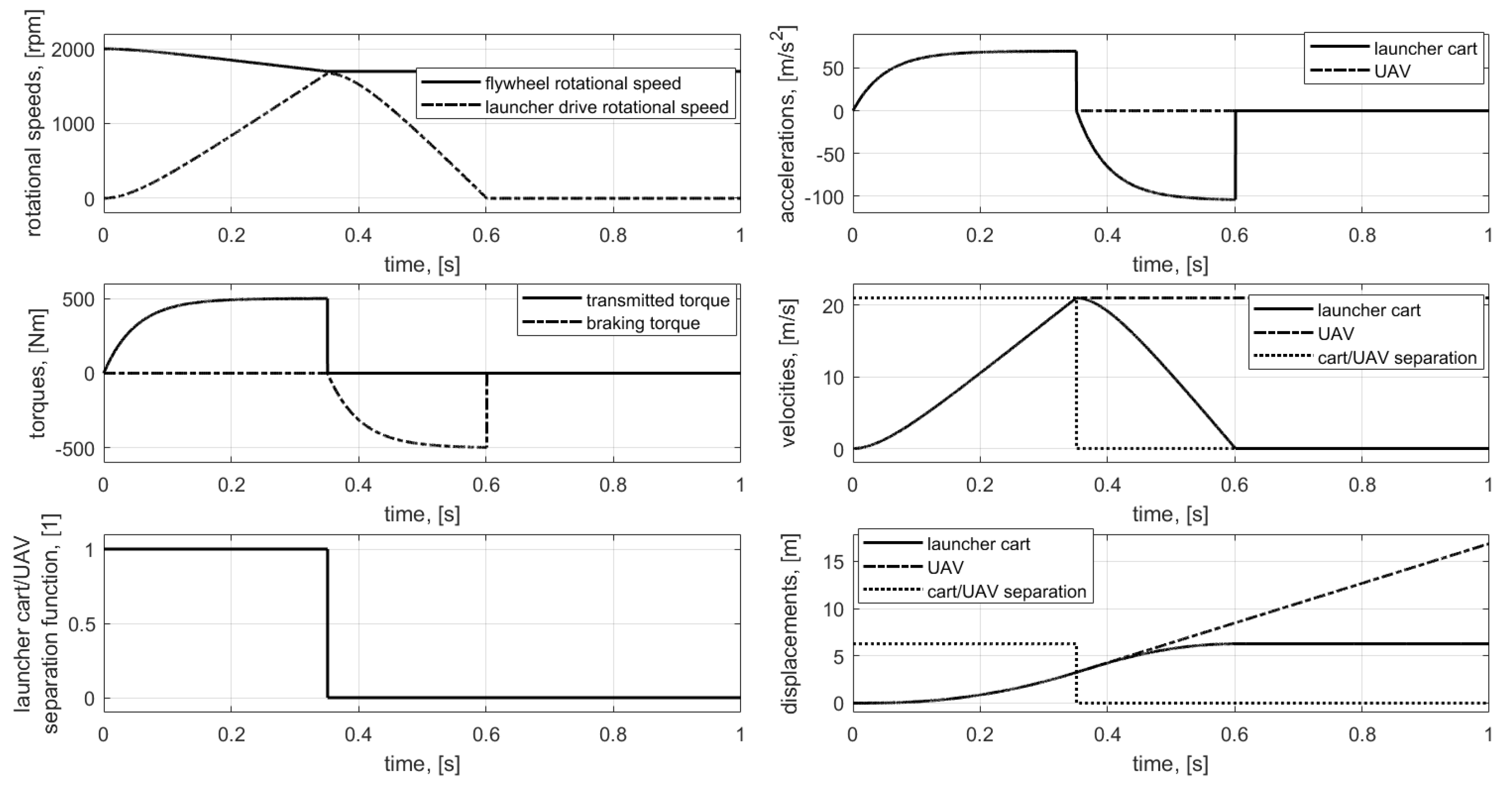
3.2. The 2nd Simulation

In the second simulation we increased x h value which was set to 6 m. The simulation time was set to 1 s with the initial speed of the flywheel unchanged ( n s 0 = 2000 rpm). The results are presented in Figure 6.
The results of the second simulation revealed that the chosen x h distance was too big because the rotational speeds of the flywheel and driving wheels attained the same values. Thus, there was no torque transfer and acceleration in the motion of the UAV. Moreover, the length of the launcher needed to be about 9 m. With x h = 6 m, in the second simulation, the UAV start velocity reached a level of about 21 m/s. That value can be also achieved with the elimination of the torque transfer dead zone.The results of the second simulation for x h = 3.25 m are presented in Figure 7.
The establishment of a proper distance for the initiation of the braking phase provided another advantage—a decrease in the total length of the launcher. In the investigated case it was approximately 6 m. Naturally, the characteristics of the system’s dynamics are strongly dependent not only on the x h value but also on the initial rotational speed of the flywheel. For instance, if we assume n s 0 = 3000 rpm and set x h = 7.25 m, a speed of about 32 m/s can be attained at the total length of the launcher at 14 m. The results of example described above are shown in Figure 8.
Of course, the increase of the launcher’s total length may cause several technical problems (especially those connected with the construction’s stiffness). Additionally, it is also necessary to remember the flexibility of the driving toothed belts [23].

3.3. The 3rd Simulation

In the third simulation the previous settings of the initial flywheel speed of n s 0 = 2000 rpm and initial braking distance x h = 2 m were used. Then, varying values for damping and friction coefficients were introduced. These are presented in Table 2.
High parameter values were chosen arbitrarily to highlight their impact on the results. The results of the third simulation are presented in Figure 9.
The influence of damping is clearly visible on the plot of rotational speeds. In the third simulation, the UAV start velocity reached a value of about 14 m/s. This was 2 m/s less than in the 1st simulation. The total length of the launcher also decreased from 4 m to approximately 3.2 m. Any discussion concerning the influence of damping and friction parameters is strictly academic in character. However, these parameters may play a crucial role in the near future comparison of results concerning simulations with experimental measurements.

4. Conclusions

Within the present paper the authors propose the use of a kinetic energy storage system as a power source for an unmanned aerial vehicle launcher. The work contains dynamics equation of the model, results of performed simulations and even a CAD model of a kinetic launcher prototype.
In general, main advantages of the kinetic launcher for UAVs are:
  • Simple design that allows to actively control the acceleration and speed of the launched objects;
  • Much higher energy density than in the magnetic launchers (the stored energy that can be used is proportional to the square of the rotational speed of the flywheel and can be adjusted for different class of lauded objects);
  • A much more compact solution than pneumatic launchers to provide similar performance (no large tank, no compressed air preparation device, no complex valves system);
  • Easy scalability for different classes of launched objects.
Simulation results clearly revealed that the proposed approach may provide an alternative for currently used pneumatic and rubber launchers. One important advantage of the described system is the possibilities it creates for motion control. When compared to magnetic launchers, the proposed solution is characterized by a much higher energy density allowing it to be used for bigger UAVs. Only a simple binary algorithm for launch control is presented in the article. However, the use of active electromagnetic systems as actuators for torque transmission makes it possible to implement any other control rule. One idea for future research is the investigation of a control system for quasi-continued stabilization of UAV acceleration during the launch using a PID controller. The work provided many conclusions connected with the practical realization of the project. First of all, it is necessary to do trials to verify whether a transmission system based on synchronous toothed belts can carry loads which may appear during the launch. It may also be necessary to supplement it with belt tension subsystems. Secondly, the linear motion of the launched object should be supported through a subsystem of linear tracks. This can improve the stability of the UAV during the launch and make it possible to use the developed kinetic launcher for airplanes of higher mass. Additionally, the CAD project assumed the utilization of an electromagnetic actuator for braking. However, other solutions mentioned within the paper, such as mechanical bumpers or rubber catch ropes may make it possible to decrease the total length of the launcher. Although the results presented in the paper are very promising, within this last paragraph it must be stated that the future of all further investigations are connected with the construction of a model in the laboratory allowing the verification of all assumptions and simulation results. The authors recognize this task as quite challenging and treat it as the next stage of any future work on the kinetic launcher for UAVs.

5. Patents

Presented in the paper concept is under patent protection no PL422977-A1 (Web of Science record from Derwent Innovations Index).

Author Contributions

Conceptualization, M.K. and L.A.; methodology, M.K.; software, M.K.; validation, M.K. and L.A.; formal analysis, M.K. and L.A.; investigation, M.K.; resources, M.K. and L.A.; data curation, M.K.; writing—original draft preparation, M.K.; writing—review and editing, L.A.; visualization, M.K.; supervision, M.K.; project administration, M.K. and L.A.; funding acquisition, M.K. and L.A. All authors have read and agreed to the published version of the manuscript.

Funding

The research was realized as part of the Bialystok University of Technology project No WZ/WM-IIM/1/2019 and funded by the Polish Ministry of Science and Higher Education.

Conflicts of Interest

The authors declare no conflict of interest.

References

  1. Buzoganny, L.E.; Pachter, M.; D’azzo, J.J. Automated control of aircraft in formation flight. In Proceedings of the AIAA Guidance—Navigation and Control Conference, Monterey, CA, USA, 9–11 August 1993; pp. 1349–1370. [Google Scholar]
  2. Pachter, M.; D’Azzo, J.; Dargan, J.L. Automatic formation flight control. J. Guid. Control Dyn. 1994, 17, 1380–1383. [Google Scholar] [CrossRef]
  3. Chen, Y.; Wang, Z. Formation control: A review and a new consideration. In Proceedings of the 2005 IEEE/RSJ International Conference on Intelligent Robots and Systems, Edmonton, AB, Canada, 2–6 August 2005; pp. 3181–3186. [Google Scholar]
  4. Gosiewski, Z.; Ambroziak, L. Formation flight control scheme for unmanned aerial vehicles. Lect. Notes Control Inf. Sci. 2012, 422, 331–340. [Google Scholar]
  5. Kownacki, C.; Ołdziej, D. Fixed-wing UAVs flock control through cohesion and repulsion behaviours combined with a leadership. Int. J. Adv. Robot. Syst. 2016, 13, 36. [Google Scholar] [CrossRef] [Green Version]
  6. Kownacki, C.; Ambroziak, L. Local and asymmetrical potential field approach to leader tracking problem in rigid formations of fixed-wing UAVs. Aerosp. Sci. Technol. 2017, 68, 465–474. [Google Scholar] [CrossRef]
  7. Arjomandi, M.; Agostino, S.; Mammone, M.; Nelson, M.; Zhou, T. Classification of Unmanned Aerial Vehicles; The University of Adelaide: Adelaide, Australia, 2006. [Google Scholar]
  8. Kondratiuk, M. Designing and Investigating of the Magnetic Coil Launcher With Controlled Acceleration of the Launching Object. Ph.D. Thesis, Bialystok University of Technology, Bialystok, Poland, 2013. (In Polish). [Google Scholar]
  9. Perkowski, W. Pneumatic launcher for unmanned aerial vehicles. Transp. Eng. 2008, 27, 181. [Google Scholar]
  10. Kolm, H.; Mongeau, P.; Williams, F. Electromagnetic launchers. IEEE Trans. Magn. 1980, 16, 719–721. [Google Scholar] [CrossRef]
  11. Patterson, D.; Monti, A.; Brice, C.; Dougal, R.; Pettus, R.; Srinivas, D.; Dilipchandra, K.; Bertoncelli, T. Design and simulation of an electromagnetic aircraft launch system. In Proceedings of the Industry Applications Conference—37th IAS Annual Meeting, Pittsburgh, PA, USA, 13–18 October 2002; pp. 1950–1957. [Google Scholar]
  12. McNab, I. A research program to study airborne launch to space. IEEE Trans. Magn. 2007, 43, 486–490. [Google Scholar] [CrossRef]
  13. Ładyżyńska-Kozdraś, E.; Falkowski, K.; Sibilska-Mroziewicz, A. Physical model of cart of UAV catapult using Meissner effect. In PTMTS Monography—Mechanics in Aviation ML-XVI; PTMTS: Warszaw, Poland, 2014; pp. 231–241. (In Polish) [Google Scholar]
  14. Ładyżyńska-Kozdraś, E.; Falkowski, K.; Sibilska-Mroziewicz, A. Vibration analysis of levitating cart of a magnetic catapult. In PTMTS Monography—Mechanics in Aviation ML-XVI; PTMTS: Warszaw, Poland, 2014; pp. 243–250. (In Polish) [Google Scholar]
  15. Sibilski, K.; Falkowski, K.; Olejnik, A. Magnetic take-off and landing system of airplanes—Project GABRIEL. In PTMTS Monography—Mechanics in Aviation ML-XVI; PTMTS: Warszaw, Poland, 2014; pp. 216–229. (In Polish) [Google Scholar]
  16. Guruge, P.; Kocer, B.B.; Kayacan, E. A novel automatic UAV launcher design by using bluetooth low energy integrated electromagnetic releasing system. In Proceedings of the 2015 IEEE Region 10 Humanitarian Technology Conference (R10-HTC), Cebu City, Philippines, 9–12 December 2015; pp. 1–4. [Google Scholar]
  17. Bhatia, D.K.; Aljadiri, R.T. Electromagnetic UAV launch system. In Proceedings of the 2017 2nd IEEE International Conference on Intelligent Transportation Engineering (ICITE), Singapore, 1–3 September 2017; pp. 280–283. [Google Scholar]
  18. Yu, Y.; Jun, W. Control strategies for the electromagnetic launcher for UAVs. In Proceedings of the 2015 34th Chinese Control Conference (CCC), Hangzhou, China, 28–30 July 2015; pp. 4486–4489. [Google Scholar]
  19. Kondratiuk, M.; Gosiewski, Z. Simulation Model of an electromagnetic multi-coil launcher for micro aerial vehicles. In Solid State Phenomena—Mechatronic Systems and Materials IV; Trans Tech Publications Ltd.: Zurich, Switzerland, 2013; pp. 406–411. [Google Scholar]
  20. Kondratiuk, M.; Gosiewski, Z. Laboratory stand of an electromagnetic multi-coil launcher for micro aerial vehicles. In Solid State Phenomena—Mechatronic Systems and Materials IV; Trans Tech Publications Ltd.: Zurich, Switzerland, 2013; pp. 334–339. [Google Scholar]
  21. Kondratiuk, M.; Gosiewski, Z. Comparison of electromagnetic coil launcher model with real-device characteristics. In Solid State Phenomena; Trans Tech Publications Ltd.: Zurich, Switzerland, 2014; Volume 214, pp. 58–66. [Google Scholar]
  22. Kondratiuk, M.; Ambroziak, L. Concept of the magnetic launcher for medium class unmanned aerial vehicles designed on the basis of numerical calculations. J. Theor. Appl. Mech. 2016, 54, 163–177. [Google Scholar] [CrossRef]
  23. Iserman, R. Mechatronic Systems Fundamentals; Springer: London, UK, 2005. [Google Scholar]
  24. IBD Wickeltechnik GmbH. Electromagnetic Powder Brakes/Clutches. Available online: www.ibd-wt.de/en/products/brakes (accessed on 1 March 2020).
Figure 1. A CAD model of the kinetic launcher design.
Applsci 10 02949 g001
Figure 2. The rotating drive part of the kinetic launcher.
Applsci 10 02949 g002
Figure 3. Parts of the kinetic launcher’s rotating drive.
Applsci 10 02949 g003
Figure 4. The synchronous drive transmission subsystem.
Applsci 10 02949 g004
Figure 5. Results of the 1st simulation.
Applsci 10 02949 g005
Figure 6. Results of the 2nd simulation for n s 0 = 2000 rpm and x h = 6 m.
Applsci 10 02949 g006
Figure 7. Results of the 2nd simulation for n s 0 = 2000 rpm and x h = 3.25 m.
Applsci 10 02949 g007
Figure 8. Results of the 2nd simulation for increased flywheel speed n s 0 = 3000 rpm and x h = 7.25 m.
Applsci 10 02949 g008
Figure 9. Results of the 3rd simulation for flywheel speed n s 0 = 2000 rpm, x h = 2 m and non-zero damping and friction parameters.
Applsci 10 02949 g009
Table 1. Constant parameters of the simulated model.
ParameterValueUnit
I s 4.75[kgm 2 ]
ω s 0 210[rad/s]
m w 5[kg]
m o 20[kg]
r n 0.12[m]
I n 0.50[kgm 2 ]
T t 0.05[s]
T h 0.05[s]
M t 0 500[Nm]
M h 0 500[Nm]
α 10[deg]
Table 2. Values of the damping and friction parameters in 3rd simulation.
ParameterValueUnit
b s 1Nm/rad/s
b n ω 1.5Nm/rad/s
b n v 0.6N/m/s
b a e r o 0.5N/m/s
μ n 0.351

