Article

Improvement of Laser Beam Fusion Cutting of Mild and Stainless Steel Due to Longitudinal, Linear Beam Oscillation

1
Fraunhofer IWS, Fraunhofer-Institute for Material and Beam Technology, 01277 Dresden, Germany
2
Institute of Manufacturing Science and Engineering, TU Dresden, 01069 Dresden, Germany
*
Author to whom correspondence should be addressed.
Appl. Sci. 2020, 10(9), 3052; https://doi.org/10.3390/app10093052
Submission received: 26 March 2020 / Revised: 14 April 2020 / Accepted: 24 April 2020 / Published: 27 April 2020
(This article belongs to the Section Mechanical Engineering)

Abstract

:
The latest research on laser beam fusion cutting (LBFC) with static beam shaping have shown a limitation in the quality of cut parts for thick steel plates (> 6 mm) when using solid state lasers. The approach of dynamic beam oscillation has recently shown to be capable of overcoming this challenge, allowing to increase the cutting speed as well as improving cut edge quality beyond the state of the art. The present paper investigates the influence of longitudinal, linear beam oscillation in LBFC of 12 mm mild and stainless steel plates by analyzing different parameters as cutting speed, burr, surface roughness, heat affected zone (HAZ), and recast layer. Reasons for the observed process improvements compared to static beam shaping have been discussed. The adjustment of the energy deposition and interaction time of the laser beam with the material found to be most relevant for optimizing the LBFC process. In particular, for beam oscillation, a gradual energy deposition takes place and increases the interaction time. This reduces the heat input in terms of HAZ and recast layer by more than 50%, resulting in high cut edge quality and more than 70% faster cutting speed.

Graphical Abstract

1. Introduction

Laser beam cutting is a highly complex process that has not yet been fully understood. The principle of laser beam fusion cutting (LBFC) is to melt material using a laser beam, superimposed by a coaxially high pressure gas jet that ejects the melt [1,2,3,4]. The inclined cutting front throughout the plate thickness characterizes the transition from solid to molten phase [1,2,3]. There are many properties, such as focal radius, laser power, gas flow, etc., affecting the LBFC [1,2,3,4,5,6]. In general, two main criteria evaluate the cutting result: productivity and cut edge quality. For productivity, the cutting speed is decisive. Furthermore, a cut edge is of high quality by absence of burr, together with a homogenous smooth surface [6,7,8,9].
To increase the process productivity, higher energy input is necessary. This could be achieved by either decreasing the focal radius or increasing the laser power [1,2,3,4,5]. Both options accelerate the cutting speed; however, the quality of the cut parts is affected [3,4,5]. For instance, the faster the cutting speed, the shorter the interaction time is between the laser beam and gas jet in respect to the material. This leads to reduced melt ejection, with the result that the melt film thickness increases [10,11,12]. The liquid melt gathers particularly in the lower part of the plate thickness. That forces a flattening of the cut front [1,11,12,13]. In turn, this results in a larger interaction area between laser beam and material, so that more laser energy is absorbed [11,12]. Heat conduction transports the absorbed laser energy into the material. This creates a melt film with a defined thickness. In consequence, as the melt film thickness increases due to the faster cutting speed, the heat conduction proceeds over a longer distance. Since the resulting heat flow is inversely proportional to the melt film thickness, an increase in the temperature difference and an increase in the interaction area between laser beam and material is required to ensure the melting process [1,10,11,12,13,14]. The accumulated melt as well as a high temperature difference causes a turbulent melt flow. This is reflected as striations on the finished cut edge [1,11,13].
A reduced melt volume accompanies also the increasing cutting speed in order to maintain the energetic balance [15]. This means that the cut kerf width narrows as the cutting speed increases. Correspondingly, less of the gas jet couples into the cut kerf and thus the melt ejection is inhibited [11,13,16,17]. The incomplete ejected melt attaches as burr at the bottom part and as a recast layer of the finished cut edge.
The described striations as well as the burr, caused by faster cutting speed, are contrary to the specifications of a high-quality cut edge. Many researchers are attempting to solve the conflict between productivity and quality in LBFC of thick metal plates. They have detected that striations could be avoided by a laminar melt flow. For this purpose, the melt film must be thin and exhibit only a minimal thermal difference [18,19,20]. A complete melt ejection prevents burr, whereby a sufficient cut kerf width is advantageous [3]. Other researchers have investigated various methods to combine the demands of high productivity and high cut quality, such as controlling the intensity distribution [21,22,23], spot size [8,24,25], spot shape [22,26], and focal position [8,15,27,28,29]. All these methods have in common that they belong to static beam shaping methods. This means that the properties of the laser beam are modified before the cutting process takes place [30,31]. One of the most promising methods to improve LBFC of thick metal plates is the enlargement of the focal radius [8,32]. As a result, the interaction area and kerf width increases, which is favorable for reducing burr formation. However, when the laser power remains constant, the intensity decreases, which reduces the cutting speed. In summary, the achieved process improvements of the static beam shaping methods do not allow high productivity while maintaining high quality for thick metal plates.
A different attempt to solve the conflict between productivity and quality is beam oscillation as dynamic beam shaping method. That implies a superimposed modification of the laser beam movement regarding the feed direction. Thus, the beam oscillates inside the generated cut kerf and thereby shapes the interaction area into an arbitrary geometry [30,31]. A main advantage of beam oscillation concept is the preserved intensity distribution of the fiber laser beam at simultaneously increased interaction area between laser beam and melt. Two of the most relevant processes using beam oscillation are electron [33,34] and laser beam welding [35,36,37,38]. In addition, first investigations on laser beam flame cutting of mild steel [39,40,41] and LBFC of stainless steel [2,30,31] have been performed with beam oscillation. All these investigations have demonstrated a high potential of process improvements regarding less process instabilities, faster processing speed, and advanced quality.
The present study aims to improve the LBFC of mild and stainless steel using longitudinal, linear beam oscillation. By changing different process variables such as amplitude and frequency, the optimal cut edge quality at maximum reachable cutting speed is investigated. The acquired results using beam oscillation method are compared against static beam shaping for both treated steels. The achieved process improvements caused by beam oscillation result from a changed energy deposition. Detailed information provides the investigation of the heat-affected zone (HAZ) by means of metallographic cross-sectional analyses. Finally, a simplified model of the energy deposition provides a first attempt to explain the changed process mechanisms in LBFC using longitudinal, linear beam oscillation.

2. Materials and Methods

2.1. Experimental Setup

Mild and stainless steel plates with 12 mm thickness were used as work pieces. These are the two most frequently laser-cut materials. Thick plate is no clear definition, but starting at about 6 mm plate thickness. Aiming to laser beam cutting applications a thickness of 12 mm absolutely represents thick plates.
The LBFC were performed with a multimode, CW fiber laser, operating at 1.07 µm wavelength. All trials utilized a laser output power of 3 kW and a randomly polarized beam. The laser power, focus radius and Rayleigh length were measured by beam diagnostics. Therefore, an optical based laser measurement device recorded the laser beam geometry in single planes along the optical axis according to DIN EN ISO 11146-2:2015. The laser beam intensity was almost top-hat distributed within the Rayleigh length and otherwise Gaussian.
A highly dynamic scanner initiated the beam oscillation and was integrated into a standard cutting head [31]. The used scanner achieved oscillation frequencies up to 4 kHz. The maximum obtainable oscillation amplitude depended on the frequency, and varied between 0 µm (static beam shaping) and 600 µm.
An overview of the main parameters summarizes Table 1.
The scheme of a longitudinal, linear beam oscillation depicts Figure 1. In the following, it will only be referred to as beam oscillation.

2.2. Determination of the Cutting Parameters

The determination of the cutting parameters differed regarding to the reference samples and the investigation of beam oscillation.
The reference samples were cut using static beam shaping. That means that the amplitude and frequency were set to zero and the laser beam was moved only by the feed. The cutting speed and focal plane iteratively adjusted to each other, in order to determine for each pair, the optimal cut edge quality at the highest possible feed rate. The cutting speed and focus position specified to 0.1 m/min and 0.1 mm, respectively. The optimal cut edge quality reached lowest possible burr and surface roughness. This procedure was performed for the two materials, providing two reference samples.
In case of investigating the beam oscillation, the frequency and amplitude was set up in pairs. For each pair and material, the cutting speed and focus position were individually adjusted following the same procedure as for the reference sample. This procedure was performed for the two materials, providing two investigation series, with each more than 35 samples.
On the one hand, static beam shaping and beam oscillation were compared within one material. An improvement of the LBFC occurred, if the cutting speed was faster or the burr height and surface roughness lower with beam oscillation than with static beam shaping. The sample with optimal cut edge quality at the highest cutting speed within one investigation series was referred to as the best result. On the other hand, the results of beam oscillation for both materials were compared to each other to investigate the influence of beam oscillation for different cutting conditions.

2.3. Characterization of the Cutting Result

The cut samples were analyzed regarding burr, surface roughness, HAZ, and recast layer. The single methods are described in the following and illustrated in Figure 2.
The burr inspection was accomplished as illustrated in Figure 2a, by digitalizing the outline of the cut edge using a graphics scanner. The used procedure consisted on dividing the cut length of the sample into five sections and detecting the maximum burr height in each one. Finally, the measured height values were averaged for evaluation.
Furthermore, average surface roughness Rz measurements were performed according to DIN EN ISO 4288:1998-04 at three different positions: 1 mm below the top surface, in the middle of the plate thickness, and 1 mm above the bottom surface. Details to the evaluation method of surface roughness depict Figure 2a. The stylus tip radius of 2 µm in the measuring plane and the deflection accuracy of 12 nm in the orthogonal plane limited the measuring resolution of the tactile method. The mean value of the three measurements evaluated the appearance of the cut edge.
Finally, metallographic cross-sectional analyses determined the HAZ and recast layer. The analysis required a separation of the samples crosswise to the cutting direction and a subsequently polishing and etching. Microscopic images recorded the cross-sections as schematically shown in Figure 2b. Area measurements characterized the HAZ and recast layer with an accuracy of 1.5 mm2. In addition, the height of the recast layer was measured (see indication in Figure 2b) with 50 µm accuracy. Since the recast layer width changes as a function of plate thickness, the quotient of area and height calculated an average recast layer width.

3. Results and Discussion

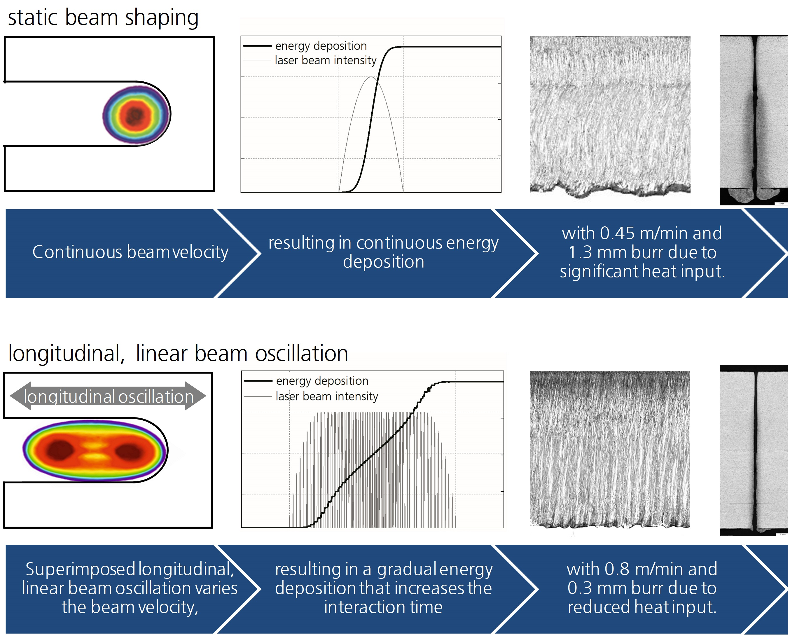
3.1. Improvement of the LBFC Due to Longitudinal, Linear Beam Oscillation

First part of this investigation deals with the proof of a process improvement using longitudinal, linear beam oscillation. The dependencies between oscillation frequency and amplitude to the three investigated characteristics-cutting speed, burr, and surface roughness-illustrate Figure 3. Linear interpolation generates tendencies between the data points. The color scale in the images contains the reference value for static beam shaping. Empty spaces of the area charts exhibit the limited amplitude as function of the frequency.
Figure 3 depicts different effects of the used beam oscillation parameters on the cutting process for stainless and mild steel. For example, the beam oscillation improves cutting speed and burr formation of stainless steel at single amplitude-frequency-combinations Figure 3a,b. Whereas, cutting speed and burr changes continuously with increasing amplitude and frequency in case of mild steel (Figure 3d,e). A steady development of the surface roughness in dependence of the oscillation parameters is obvious for both steels (Figure 3c,f). In addition, the three characteristics improve, compared to their reference values for both steels. Similar oscillation parameter achieves a faster cutting speed for both steels. However, the oscillation parameters for reaching low burr height and small surface roughness are not identical for the two investigated materials.
The best result for stainless steel cut with beam oscillation has 83% faster cutting speed and 30% less burr height compared to the reference sample. However, the average surface roughness rises by 25%. A star in Figure 3 distinguishes the corresponding oscillation parameters.
In case of mild steel (Figure 3d–f), all three characteristics reveal a similar dependency on the oscillation parameters. Higher amplitudes increase the cutting speed and decreasing burr as well as surface roughness. The correlation with the oscillation frequency is reverse. An increasing frequency reduces the cutting speed. In addition, burr, as well as surface roughness, exposes a non-linear dependency at higher frequencies. Both parameters increase up to about 2 kHz and slightly decrease for higher frequencies. An improvement of all three characteristics achieves a frequency below 1 kHz in combination with more than 200 µm amplitude. The best result for mild steel cut with beam oscillation accomplishes 500 Hz frequency combined with a 300 µm amplitude. In fact, this beam oscillation parameters increases the cutting speed by 76%, with a decreased burr height (77%) and lower surface roughness (38%) compared to the reference sample.
Figure 4 depicts the cut edges optimized by the used beam oscillation compared to static beam shaping. The oscillation parameters used for this purpose are marked with a star in Figure 3. The reference cuts of stainless (Figure 4a) and mild steel (Figure 4c) exhibit distinct burr heights. Another obvious difference between the samples cut with static beam shaping and beam oscillation is the cut edge appearance (striation curvature). The cut edges of the reference samples show striations with several directional changes, whereas beam oscillation creates rather straight striations.
There is another facet of quality improvement due to beam oscillation for mild steel. Typically, mild steel with a plate thickness of 12 mm is cut with oxygen as an assisting gas [5,7]. However, an oxygen layer results on the cut edge, which is usually removed for subsequent production steps [5,8]. An inert assist gas as nitrogen avoids such oxygen layer and requires no post-treatment of the cut edge. A high-quality laser beam fusion cut of mild steel needs more laser power due to the missing energy of the oxygen reaction and the high heat conductivity coefficient. On that account, state of the art cutting machines apply more than 8 kW laser power to enable this cutting task. In contrast, beam oscillation makes it possible to cut thick mild steel with nitrogen and just 3 kW laser power as presented in Figure 4d.

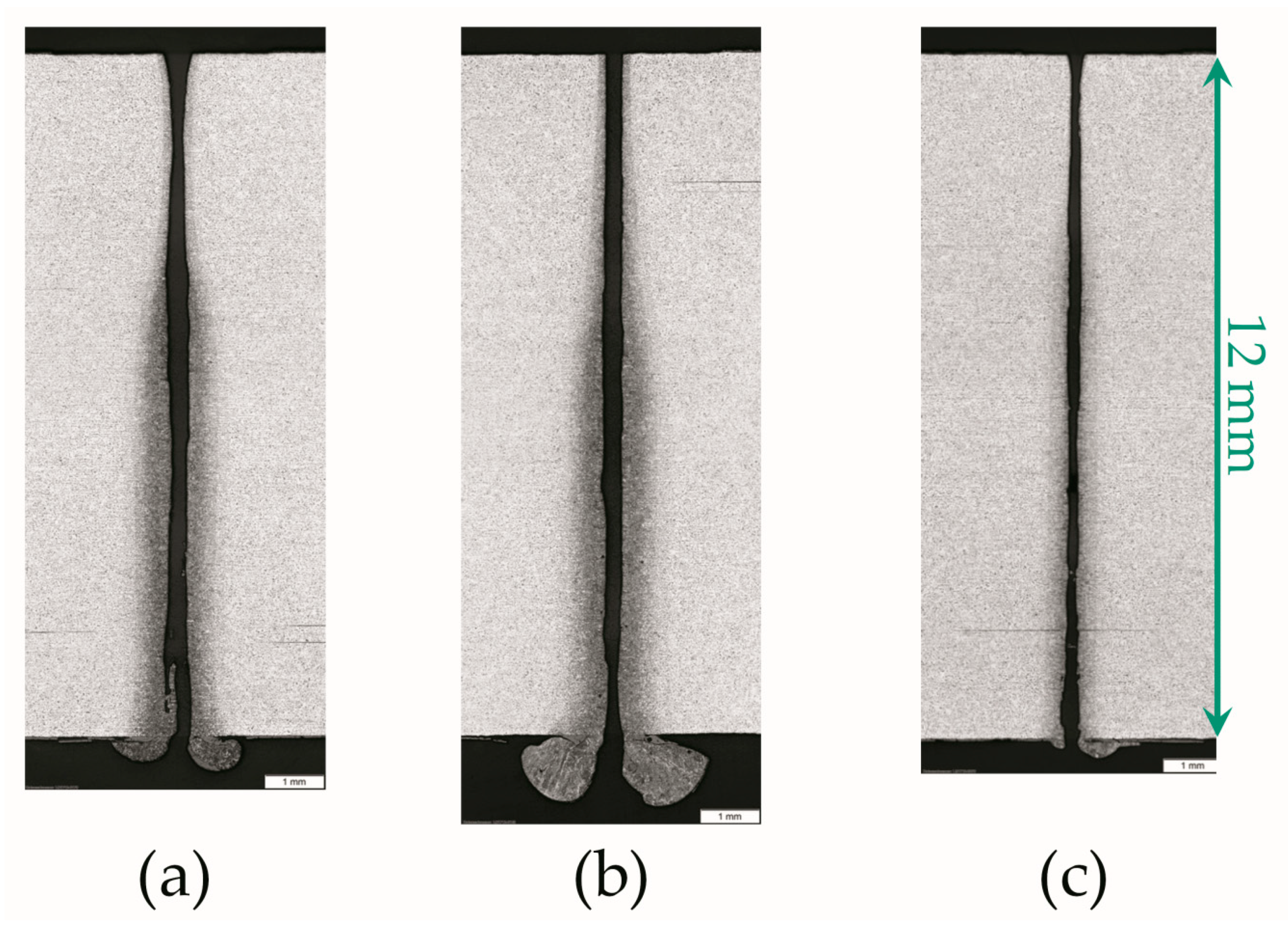
3.2. Metallographic Analysis of Mild Steel to Reveal the Thermal Energy Deposition

Whereas the first part of this investigation was dedicated to proof the process improvement using beam oscillation, the second part focused on understanding the mechanisms that lead to these improvements. Therefore, the influence of beam oscillation on the energy deposition during LBFC has been analyzed. Laser beam energy converts mainly into thermal energy during LBFC in order to melt the material. This energy absorbs not only on the cut front, but also on the lateral cut edge and creates the HAZ or recast layer. A method for visualizing the HAZ and recast layer inside the material consists on performing polished cross-sections of the cut materials as depicted in Figure 5. The metallographic analysis has been performed for selected mild steel samples. The reason is due to the three times higher heat conduction coefficient of mild steel compared to stainless steel, which tends to form a pronounced HAZ and recast layer. The cut kerf area corresponds to the black area of the microscopic images in Figure 5a,b and represents the boundary of the recast layer in one direction. Microstructural transformations between HAZ and recast layer indicate the second border. The recast layer represents the portion of the melt film that was not completely ejected and in general attaches at the lower part of the cut edge. This material heats up into the molten phase and solidifies subsequently, which is evident through the cast structure (Figure 5b). A ferritic-pearlitic structure is distinctive for the basic material of mild steel. The pearlite grains transforming through heat input and indicate the beginning HAZ (Figure 5b,c).
It is known that high-quality cuts require a small HAZ with preferably no recast layer [3,11,19,42]. Moreover, parallel and ample cut kerfs simplify the removal of the cut parts from the remaining plate. Figure 5a depicts a polish of cross-section cut with static beam shaping. Contrary to ideal desires, the cut kerf varies greatly and has no straight-line boundaries. The recast layer attaches from approximately half the plate thickness and opens into strong burr adhesion on the bottom side of the plate. The HAZ is evident over the entire plate thickness. At the top of the plate is the HAZ layer uniformly thin and broadens significantly when the recast layer adhesion initiates.
Figure 6 shows exemplary polish of cross-sections of mild steel cut with very different beam oscillation parameters. The images have been selected since they represent different behaviors. For example, for 60 µm amplitude and 250 Hz frequency (Figure 6a) are the cut kerf walls still wavy, but there is just one constriction. The beginning of the recast layer adhesion shifts slightly towards the top side of the plate and narrows compared to the static beam shaping from Figure 5a. The burr height and HAZ area reduces. Increasing the frequency to 4000 Hz (Figure 6b) results in parallel, straight cut kerf walls. The recast layer and HAZ are not significantly different from the results obtained in Figure 6a, but the burr height grows. The increased amplitude (Figure 6c) minimizes the recast layer, HAZ, and burr significantly; hence, no heat input is visible on the top side of the plate.
The influence of the oscillation parameters on the HAZ and recast layer width is shown in Figure 7. A rising frequency increases the HAZ area with a maximum at 2 kHz (Figure 7a). Additionally, the average recast layer width slightly increases with rising frequency. Increasing amplitudes minimizes the HAZ area, reaching its minimum at 400 µm amplitude. The average recast layer width shows a similar behavior; however, the minimum is located at 300 µm amplitude. Compared with the static beam shaping, both the HAZ area and average recast layer width reduces at all oscillation parameters (see reference values in Figure 7). The best cut quality (marked with a star in Figure 7) was achieved at frequencies below 1 kHz using amplitudes above 200 µm. In this case, the HAZ area and the recast layer width decreases by 55% and 75%, respectively, compared to static beam shaping.
According to the obtained results presented in Figure 3 and Figure 7, two main effects were observed when using beam oscillation, compared to static beam shaping: (i) The cutting speed increases significantly and (ii) The cut edge quality improves considerable. A simplified model for the beam oscillation during LBFC suggests an explanation for both effects.

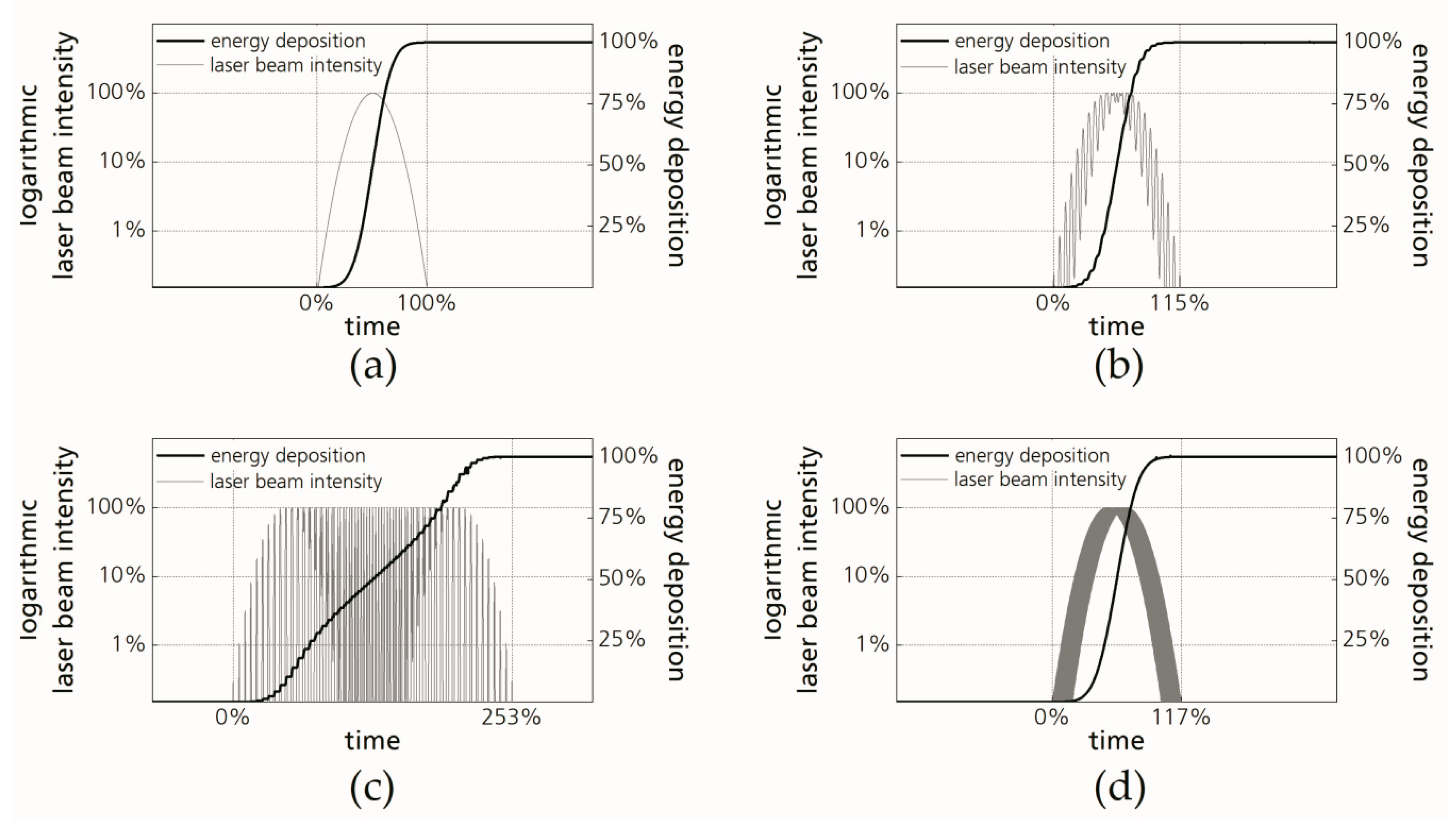
3.3. Explanatory Approach of the Process Improvements Due to Beam Oscillation Based on an Energetic Consideration

In fact, the cutting speed depends on the energy balance in the cutting process [15]. A change of the cutting speed at constant laser power requires a different energy deposition as function of time. Figure 8 illustrates which requirements beam oscillation meet to increase the cutting speed. In the case of static beam shaping, the energy deposits continuously while the laser beam passes once a certain position at a constant cutting speed. In contrast, with beam oscillation, the laser beam does not move uniformly. Furthermore, large amplitudes increase the interaction area of the laser beam with the material, compared to static beam shaping. This represents the beam diagnostic in Figure 8a,b. The indicated interaction area for beam oscillation (Figure 8b) is valid, when the measuring time is longer than one oscillation period. Figure 8c points out that the alternating laser beam velocity causes the intensity distribution of beam oscillation in Figure 8b. At the inflection points, where the oscillation speed is zero, the intensity is maximal. In addition, for large amplitudes, the laser beam reaches a higher velocity and the intensity distribution covers a larger interaction area during one oscillation period. The laser beam velocity also speeds up at an increasing frequency; however, the interaction area remains constant. Accordingly, not only does the cutting speed determine the interaction time of laser beam and material, but also the oscillation parameters.
A low amount of laser energy deposits locally due to the fast laser beam velocity of beam oscillation. Thus, the complete melting of the material requires multiple passes over a certain position. The energy input is therefore gradual, instead of continuous as in static beam shaping. Figure 9 illustrates that by plotting both the local intensity profile as well as the energy deposition for a certain position along the cut path. Considered are the static beam shaping and three different beam oscillations, whereby the cutting speed and focal plane is equal within all four scenarios. The interaction time of the laser beam at a fixed position corresponds to the time until the intensity has dropped to zero.
The shortest interaction time obtains static beam shaping in Figure 9a. In contrast, the combination of small amplitude and low frequency (Figure 9b) illustrates a cyclic time-dependency for the laser beam intensity. This causes a gradual energy input, and thus, a 15% longer interaction time compared with static beam shaping. This effect is significantly more predominant at higher amplitudes (Figure 9c). At a cutting speed comparable to static beam shaping (0.5 m/min), the interaction time extends to 253%. The fast laser beam motion for high oscillation frequencies (Figure 9d) has a similar interaction time as shown in Figure 9b. However, it creates a more homogenous intensity profile, comparable to static beam shaping.
Static beam shaping has the lowest interaction time in Figure 9 and reaches the slowest cutting speed in Figure 3a. Beam oscillation with 500 µm amplitude and 250 Hz frequency exhibit the longest interaction time and achieves the fastest cutting speed (see Figure 3a). As the total amount of energy deposition is equal for all charts in Figure 9, a correlation is suggested between interaction time, the corresponding pulse-like intensity profile, and the resulting cutting speed.
To increase the cutting speed, more material has to melt per time. This requires high heat conduction rates through the melt film up to the solid phase. Heat conduction depends mainly on the material constants, the temperature difference within the melt film, and the melt film thickness. The laser beam affects only the latter two. Increasing the temperature difference and decreasing the melt film thickness raises the heat conduction rate. According to the state of the art, a pulsed energy deposition is a common way to achieve a high heat conduction rate combined with minimized heat conduction losses for LBFC of thin sheets [43]. Because beam oscillation creates a similar intensity sequence as a pulse regime (Figure 9), similar effects to the cutting process are also expected. One is an improved heat conduction rate. Beam oscillation is assumed to generate this by a significant volatile temperature profile, with high peaks, but also frequent heat dissipation. This enables a thin, but punctually hot melt film with high heat conduction rate, which in turn enables the obtained high cutting speeds (see Figure 3). Further investigations have to confirm this assumption by analyzing the temperature profile during the cutting process.
The second effect to explain is the considerable improved cut edge quality at high amplitudes. The high heat conduction rate in combination with the extended interaction time for optimized beam oscillation parameters (Figure 9c) is expected to improve the melt ejection. Indications deliver the HAZ and recast layer analysis (Figure 7). Previous investigations obtained burr-free and smooth cut edges when the material has a small HAZ and recast layer width [3,11,19,42]. Furthermore, for static beam shaping, the HAZ area decreases, whereas the recast layer width grows at an accelerating cutting speed [11,19,42,44,45,46]. However, referring to the results shown in Figure 3 and Figure 7, a significant correlation has been observed between the amplitude, cutting speed, HAZ area, burr height, and surface roughness for beam oscillation. The average recast layer width decreases with an increasing amplitude, respectively, cutting speed. This is contrary to static beam shaping. Again, the interaction time is the cause. The gradual energy deposition keeps the melt film thickness low due to the volatile temperature profile. Due to the longer overall interaction time of beam oscillation compared to static beam shaping (see Figure 9), the irradiated material remains longer in the molten phase. Thus, the available time to eject the already thin melt film from the cut kerf increases and makes the melt ejection even more effective. In turn, this leads to a small recast layer and HAZ, respectively, low burr height and smooth surface roughness. The interaction time extends with increasing amplitude (see Figure 9b,c), resulting in a greater quality improvement.
Summarizing, the present investigation demonstrated for the first time that a pulsed energy deposition in LBFC caused by beam oscillation achieves process improvements for thick plates. From this consideration, it seems natural that the limited productivity and quality in thick plate cutting for static beam shaping results from the continuous energy deposition and the limited interaction time. Overcoming the existing process limitations needs more degrees of freedom to modify the properties of the laser beam. Beam oscillation is such a method. It is capable to extend the interaction time and has a positive impact on the melting process, due to the gradual energy deposition.

4. Conclusions

This study presents the improvement of productivity and quality in LBFC of 12 mm mild and stainless steel due to longitudinal, linear beam oscillation. Although the optimal oscillation parameters for both materials are close to each other, there are different dependencies from amplitude and frequency. For instance, the best result for stainless steel achieves 83% faster cutting speed and 30% less burr height than static beam shaping. However, the average surface roughness rises by 25%. In fact, mild steel reaches an increase of the cutting speed by 76%, with a decreased burr height (77%) and lower surface roughness (38%) compared to static beam shaping. In fact, static beam shaping for LBFC with a given laser power of 3 kW cannot reach the cutting speeds, that are addressed by longitudinal, linear beam oscillation to cut 12 mm mild or stainless steel.
The reason for the reported improvements explains the evaluation of the temporal energy deposition during the process. Applying beam oscillation deposits the laser beam energy gradually instead of continuously, as in case of static beam shaping. That extends the interaction time. Since the interaction time affects the melt dynamics, a simplified model is suggested to explain a most efficient melt ejection and thus ensuring high-quality and fast cuts.
Further investigations need to prove the volatile temperature profile due to longitudinal, linear beam oscillation on the one hand; on the other hand, the beam oscillation is expected to influence the angle of incidence. The extent to which the process improves needs to be considered.

Author Contributions

Conceptualization, C.G. and T.P.; Data curation, C.G.; Formal analysis, C.G.; Funding acquisition, C.G., T.P., and P.H.; Investigation, C.G. and S.S.; Methodology, C.G., T.P., and S.S.; Project administration, C.G.; Resources, P.H.; Validation, C.G. and T.P.; Visualization, C.G.; Writing—original draft, C.G. and T.P.; Writing—review and editing, P.H. and A.F.L. All authors have read and agreed to the published version of the manuscript.

Funding

This research received no external funding.

Conflicts of Interest

The authors declare no conflict of interest.

References

  1. Olsen, F.O. Fundamental mechanisms of cutting front formation in laser cutting. Proc. SPIE 1994, 2207, 402–413. [Google Scholar] [CrossRef]
  2. Mahrle, A.; Bartels, F.; Beyer, R.E. Theoretical aspects of the process efficiency in laser beam cutting with fiber lasers. LIA Publ. 2008, 611, 703–712. [Google Scholar] [CrossRef]
  3. Wandera, C.; Kujanpää, V. Characterization of the melt removal rate in laser cutting of thick-section stainless steel. J. Laser Appl. 2010, 22, 62–70. [Google Scholar] [CrossRef]
  4. Hügel, H.; Graf, T. Laser in der Fertigung: Grundlagen der Strahlquellen, Systeme, Fertigungsverfahren, 3rd ed.; Springer Vieweg: Wiesbaden, Germany, 2014; pp. 218–259. [Google Scholar]
  5. Powell, J.; Petring, D.; Pocorni, J.; Kaplan, A.F.H. LIA Guide to High Power Laser Cutting; LIA: Orlando, FL, USA, 2017; pp. 1–75. [Google Scholar]
  6. Hilton, P.A. Cutting stainless steel with disc and CO2 lasers. In Proceedings of the 5th International Congress on Laser Advanced Materials Processing, LAMP, Kobe, Japan, 29 June–2 July 2009; pp. 1–6. [Google Scholar]
  7. Wandera, C.; Salminen, A.; Kujanpää, V. Inert gas cutting of thick-section stainless steel and medium-section aluminum using a high power fiber laser. J. Laser Appl. 2009, 21, 154–161. [Google Scholar] [CrossRef]
  8. Wandera, C.; Kujanpää, V. Optimization of parameters for fibre laser cutting of a 10 mm stainless steel plate. Proc. Inst. Mech. Eng. Part B J. Eng. Manuf. 2011, 225, 641–649. [Google Scholar] [CrossRef]
  9. Orishich, A.M.; Malikov, A.G.; Shulyatyev, V.B.; Golyshev, A.A. Experimental comparison of laser cutting of steel with fiber and CO2 lasers on the basis of minimal roughness. Phys. Procedia 2014, 56, 875–884. [Google Scholar] [CrossRef] [Green Version]
  10. Amara, E.H.; Kheloufi, K.; Tamsaout, T.; Fabbro, R.; Hirano, K. Numerical investigations on high-power laser cutting of metals. Appl. Phys. A 2015, 119, 1245–1260. [Google Scholar] [CrossRef]
  11. Kheloufi, K.; Amara, E.H.; Benzaoui, A. Numerical simulation of transient three-dimensional temperature and kerf formation in laser fusion cutting. J. Heat Transf. 2015, 137, 112101. [Google Scholar] [CrossRef]
  12. Petring, D.; Arntz, D.; Stoyanov, S.; Schneider, F. Effects of beam power and power density distribution on process and quality issues during fiber laser cutting of stainless steel sheet metal. In Proceedings of the 10th Proceeding LiM, Munich, Germany, 24–27 June 2019; WLT: Munich, Germany, 2019; Volume 215, pp. 1–10. [Google Scholar]
  13. Sparkes, M.; Gross, M.; Celotto, S.; Zhang, T.; O’Neill, W. Practical and theoretical investigations into inert gas cutting of 304 stainless steel using a high brightness fiber laser. J. Laser Appl. 2008, 20, 59–67. [Google Scholar] [CrossRef]
  14. Kovalev, O.B.; Zaitsev, A.V. Modeling of the free-surface shape in laser cutting of metals. 2. model of multiple reflection and absorption of radiation. J. Appl. Mech. Tech. Phys. 2005, 46, 9–13. [Google Scholar] [CrossRef]
  15. Scintilla, L.D.; Tricarico, L.; Wetzig, A.; Beyer, R.E. Investigation on disk and CO2 laser beam fusion cutting differences based on power balance equation. IJMTM 2013, 69, 30–37. [Google Scholar] [CrossRef]
  16. Tani, G.; Tomesani, L.; Campana, G.; Fortunato, A. Quality factors assessed by analytical modelling in laser cutting. Thin Solid Films 2004, 453, 486–491. [Google Scholar] [CrossRef]
  17. Zhang, C.; Wen, P.; Yao, Z.; Yuan, Y.; Fan, X. Visualization of flow separation inside cut kerf during laser cutting of thick sections. J. Laser Appl. 2016, 28, 022204. [Google Scholar] [CrossRef] [Green Version]
  18. Schulz, W.; Kostrykin, V.; Niessen, M.; Michel, J.; Petring, D.; Kreutz, E.W.; Poprawe, R. Dynamics of ripple formation and melt flow in laser beam cutting. J. Phys. D Appl. Phys. 1999, 32, 1219–1228. [Google Scholar] [CrossRef]
  19. Hirano, K.; Fabbro, R. Possible explanations for different surface quality in laser cutting with 1 and 10 µm beams. J. Laser Appl. 2012, 24, 012006. [Google Scholar] [CrossRef] [Green Version]
  20. Halm, U.; Niessen, M.; Arntz, D.; Gillner, A.; Schulz, W. Simulation of the temperature profile on the cutting edge in laser fusion cutting. In Proceedings of the 10th Proceeding LiM, Munich, Germany, 24–27 June 2019; WLT: Munich, Germany, 2019; Volume 244, pp. 1–6. [Google Scholar]
  21. Laskin, A.; Williams, G.; Demidovich, A. Applying refractive beam shapers in creating spots of uniform intensity and various shapes. Proc. SPIE 2010, 7579, 75790N. [Google Scholar] [CrossRef]
  22. Doan, H.D.; Noaki, I.; Kazuyoshi, F. Laser processing by using fluidic laser beam shaper. Int. J. Heat Mass Transf. 2013, 64, 263–268. [Google Scholar] [CrossRef]
  23. Fuse, K. Beam shaping for advanced laser materials processing. Laser Tech. J. 2015, 12, 19–22. [Google Scholar] [CrossRef] [Green Version]
  24. Goppold, C.; Zenger, K.; Herwig, P.; Wetzig, A.; Mahrle, A.; Beyer, E.R. Experimental analysis for improvements of process efficiency and cut edge quality of fusion cutting with 1 µm laser radiation. Phys. Procedia 2014, 56, 892–900. [Google Scholar] [CrossRef]
  25. Hilton, P.A.; Lloyd, D.; Tyrer, J.R. Use of a diffractive optic for high power laser cutting. J. Laser Appl. 2016, 28, 012014. [Google Scholar] [CrossRef] [Green Version]
  26. Kaakkunen, J.J.J.; Laakso, P.; Kujanpää, V. Adaptive multibeam laser cutting of thin steel sheets with fiber laser using spatial light modulator. J. Laser Appl. 2014, 26, 032008. [Google Scholar] [CrossRef]
  27. Powell, J.; Tan, W.K.; Maclennan, P.; Rudd, D.; Wykes, C.; Engstrom, H. Laser cutting stainless steel with dual focus lenses. J. Laser Appl. 2000, 12, 224–231. [Google Scholar] [CrossRef]
  28. Haas, G.J. Adaptive optics. Ind. Laser Solut. 2002, 17, 1–5. [Google Scholar]
  29. Laskin, A.; Volp, J.; Laskin, V.; Ostrun, A. Refractive multi-focus optics for material processing. In Proceedings of the 35th Proceeding ICALEO, San Diego, CA, USA, 16–20 October 2016; LIA: Orlando, FL, USA, 2016; Volume 1402, pp. 1–6. [Google Scholar] [CrossRef]
  30. Goppold, C.; Pinder, T.; Herwig, P.; Mahrle, A.; Wetzig, A.; Beyer, E.R. Beam oscillation—Periodic modification of the geometrical beam properties. In Proceedings of the 8th Proceeding LiM, Munich, Germany, 22–25 June 2015; WLT: Munich, Germany, 2015; Volume 112, pp. 1–8. [Google Scholar]
  31. Goppold, C.; Pinder, T.; Herwig, P. Transient beam oscillation with a highly dynamic scanner for laser beam fusion cutting. Adv. Opt. Technol. 2016, 5, 61–70. [Google Scholar] [CrossRef]
  32. Mahrle, A.; Beyer, R.E. Theoretical aspects of fibre laser cutting. J. Phys. D Appl. Phys. 2009, 42, 175507. [Google Scholar] [CrossRef]
  33. Von Dobeneck, D.; Löwer, T.; Adam, V. Elektronenstrahlschweißen. Das Verfahren und Seine Industrielle Anwendung für Höchste Produktivität; Verlag Moderne Industrie: Landsberg/Lech, Germany, 2001; pp. 1–70. [Google Scholar]
  34. Matthes, K.J.; Richter, E. Schweißtechnik. Schweißen von Metallischen Konstruktionswerkstoffen, 4th ed; Carl Hanser: Munich, Germany, 2008; pp. 366–382. [Google Scholar]
  35. Mahrle, A.; Beyer, R.E. Modeling and simulation of the energy deposition in laser beam welding with oscillatory beam deflection. In Proceedings of the 26th Proceeding ICALEO, Orlando, FL, USA, 29 October–1 November 2007; Lu, Y., Ed.; LIA: Orlando, FL, USA, 2007; Volume 1805, pp. 1–10. [Google Scholar] [CrossRef]
  36. Schweier, M.; Heins, J.F.; Haubold, M.W.; Zaeh, M.F. Spatter formation in laser welding with beam oscillation. Phys. Procedia 2013, 41, 20–30. [Google Scholar] [CrossRef] [Green Version]
  37. Müller, A.; Goecke, S.-F.; Sievi, P.; Albert, F.; Rethmeier, M. Laser beam oscillation strategies for fillet welds in lap joints. Phys. Procedia 2014, 56, 458–466. [Google Scholar] [CrossRef] [Green Version]
  38. Keßler, B.; Dittrich, D.; Brenner, B.; Standfuß, J.; Beyer, R.E. Laserstrahl-Mehrlagen-Engstspalt-Schweißen von Alloy 617occ—Fertigen von Schlüsselkomponenten zukünftiger energieeffizienter und ressourcensparender Hochtemperatur-Prozesse. DVS Berichte 2016, 327, 333–339. [Google Scholar]
  39. Arai, T.; Riches, S. Thick plate cutting with spinning laser beam. Proc. ICALEO 1997, 83, 19–26. [Google Scholar] [CrossRef]
  40. Morimoto, Y.; He, D.; Hijikata, W.; Shinshi, T.; Nakai, T.; Nakamura, N. Effect of high-frequency orbital and vertical oscillations of the laser focus position on the quality of the cut surface in a thick plate by laser beam machining. Precis. Eng. 2015, 40, 112–123. [Google Scholar] [CrossRef]
  41. Harris, J.; Brandt, M. Cutting 50 mm thick mild steel plate with a Nd:YAG laser. In Proceedings of the 22th Proceeding ICALEO, Jacksonville, FL, USA, 13–16 October 2003; LIA: Orlando, FL, USA, 2003; Volume 1102, pp. 1–13. [Google Scholar] [CrossRef]
  42. Aggoune, S.; Amara, E.H.; Debiane, M. Effects of the velocity and the nature of the inert gas on the stainless steel laser cut quality. FDMP 2013, 9, 61–75. [Google Scholar] [CrossRef]
  43. Adrian, H.A.L.; Ascari, A.; Fortunato, A.; Romoli, L. Long-pulse quasi-CW laser cutting of metals. Int. J. Adv. Manuf. Technol. 2017, 94, 155–162. [Google Scholar] [CrossRef]
  44. Scintilla, L.D.; Sorgente, D.; Tricarico, L. Experimental investigation on fiber laser cutting of Ti6Al4V thin sheet. Adv. Mater. Res. 2011, 264, 1281–1286. [Google Scholar] [CrossRef]
  45. Miraoui, I.; Boujelbene, M.; Zaied, M. High-power laser cutting of steel plates: Heat affected zone analysis. Adv. Mater. Sci. Eng. 2016, 2016, 1–8. [Google Scholar] [CrossRef] [Green Version]
  46. Jarosz, K.; Löschner, P.; Nieslony, P. Effect of cutting speed on surface quality and heat-affected zone in laser cutting of 316L stainless steel. Procedia Eng. 2016, 149, 155–162. [Google Scholar] [CrossRef] [Green Version]
Figure 1. Schematic beam movement of (a) Static beam shaping; (b) Longitudinal, linear beam oscillation.
Applsci 10 03052 g001
Figure 2. Characterization methods: (a) Cross-sectional view along the cutting direction verifies the cut edge quality: maximum burr height was detected in five sections, surface roughness Rz was measured along three lines; (b) Cross-sectional view across the cutting direction investigates the laser beam energy deposition: heat affected zone (HAZ) and recast layer were studied as area measurements and the height of the recast layer was recorded.
Applsci 10 03052 g002
Figure 3. Contour plots of evaluated cutting results for cutting speed (a,d), burr height (b,e), and surface roughness (c,f) for 12 mm stainless steel (a,b,c) and 12 mm mild steel (d,e,f) as a function of frequency and amplitude using longitudinal, linear beam oscillation. The stars denote the best cutting result. The reference values (Ref) corresponds to the values obtained with static beam shaping.
Applsci 10 03052 g003
Figure 4. Cut edges of 12 mm stainless steel (a and b) and 12 mm mild steel (c and d) with static beam shaping (a and c are references) and longitudinal, linear beam oscillation (b and d) with the oscillation parameters marked as star in Figure 3.
Applsci 10 03052 g004
Figure 5. Microscopically images of polished and etched cross-sections of 12 mm laser beam fusion cut mild steel using static beam shaping indicates the cut kerf, recast layer, heat affected zone (HAZ), and basic material at different magnifications: (a) 20fold; (b) 100fold; (c) 250fold.
Applsci 10 03052 g005
Figure 6. Microscopically images of polished and etched cross-sections of 12 mm laser beam fusion cut mild steel using different oscillation parameters: (a) 60 µm amplitude and 250 Hz frequency; (b) 60 µm amplitude and 4000 Hz frequency; (c) 500 µm amplitude and 250 Hz frequency.
Applsci 10 03052 g006
Figure 7. Contour plots of: (a) HAZ area; (b) Average recast layer width for 12 mm mild steel as a function of the oscillation frequency and amplitude. The stars denote the best cutting result. The reference values (Ref) correspond to the values obtained with static beam shaping.
Applsci 10 03052 g007
Figure 8. Beam diagnostic visualizes the interaction area and average intensity distribution of: (a) Static beam shaping; (b) Linear beam oscillation; (c) The laser beam velocity is constant for static beam shaping and alternates in case of longitudinal, linear beam oscillation.
Applsci 10 03052 g008
Figure 9. Schematic comparison of the local intensity profile and energy deposition for one certain material position along the cut path as function of the time for: (a) Static laser beam shaping; and different values of the longitudinal, linear beam oscillation parameters: (b) 60 µm amplitude and 250 Hz frequency; (c) 500 µm amplitude and 250 Hz frequency; (d) 60 µm amplitude and 4000 Hz frequency. All axes of the four charts are scaled equally. Cutting speed and focal plane are constant and heat conduction and melt ejection have been disregard.
Applsci 10 03052 g009
Table 1. Overview of the most relevant process conditions.
CharacteristicData
laser power3 kW
wavelength1070 nm
focus radius60 µm
Rayleigh length1.1 mm
oscillation amplitude0–600 µm
oscillation frequency0–4 kHz
oscillation typelongitudinal, linear
assist gasnitrogen
gas pressure1.8 MPa
nozzle diameter3 mm
stand-off distance0.7 mm
materialmild steel 1.0038
stainless steel 1.4301
plate thickness12 mm

