Featured Application
A four-element wideband multiple-input multiple-output (MIMO) antenna is optimized using a genetic algorithm (GA). The antenna consists of a stub, four reduced ground planes, and four T-shaped radiating elements. The behavior of the antenna is analyzed with the following parameters: return loss, electromagnetic interference (EMI), and operating frequency. The antenna design is applicable to different applications. A 2K factorial design is used to identify the key design parameters responsible for affecting the above-mentioned performance indexes of the antenna. A GA optimization technique is utilized to increase the frequency range, where the return loss is less than −10 dB, while its EMI is reduced to within a 1 m sphere of radiation, so as to reduce the threat of the antenna to nearby devices. The increased frequency range also makes it suitable for various applications such as satellite communication, imaging, and radar communication.
Abstract
In this paper, optimization of a miniaturized multiple-inputs multiple-outputs (MIMO) antenna was performed. This antenna was composed of a T-shape radiating element with stub and reduced ground plane and a compact size of 25 mm × 25 mm × 1.6 mm. The behavior of antenna was evaluated in terms of return loss (S-parameter < −10 dB), electromagnetic interference (EMI), and operation frequency. The antenna design is applicable to many applications. A 2K factorial design combined with a genetic algorithm (GA) optimization technique were used to identify the key design parameters responsible for affecting the performance quality of the antenna. Optimization of the antenna design for EMI reduction was utilized, and the optimal design showed enhanced bandwidth of the antenna and reduced power consumption.
1. Introduction
Antennas are used in several aspects of life, from human body networks to space communication. There are many antennas around us, and hence their interference with one another and with other electronic gadgets must be reduced. Electromagnetic interference (EMI) between transmitting and receiving antennas is an important consideration for relative antenna placement [1]. Whether onboard or offboard, radiating and receiving electronic appliances such as antennas can interfere with other such devices and can reduce their application effectiveness.
Multipath propagation issues arise in conventional transmission systems due to signal degradation in the transmission medium of the transmitter and receiver. To overcome this issue, multiple-input multiple-output (MIMO) technology can be implemented [2,3,4,5,6,7,8]. A variety of research on MIMO antennas can be found in the literature with an aim of achieving high quality, isolated signals along with compact antenna size to overcome the aforementioned issues.
Tian et al. [9] and Liu et al. [10] discussed channel capacity to enhance antenna efficiency by reducing the mutual coupling and effects of spatial correlation under the Rayleigh fading channel assumption. Abdul et al. [11] and Khalighi et al. [12] proposed a method to identify the number of antennas at the asymmetric base station as well as in mobile units in order to increase the effectiveness of the station. Du et al. [13] addressed the need to optimize overall MIMO system capacity, which includes the unequal costs of antennas at both channels.
In antenna design optimization, algorithms inspired by natural processes have been applied, and they are genetic algorithms (GAs) [14,15,16,17], particle swarm optimization (PSO) [18,19], and their variants [20,21]. Genetic algorithm (GA)-based optimization algorithms have been utilized for antenna array positioning and have been successful in finding optimized antenna schemes [22]. These optimization algorithms do not consider the assumptions about the design, and the generation of optimal parameters is necessary to meet the defined design criteria [23].
In this work, we wanted to optimize the MIMO antenna design with respect to its EMI. The factors that affect the EMI can be classified into its structural parameters and the material properties of the substrate. This work focused on the structural parameters only. However, there are ten structural parameters, as we discuss later, making optimization challenging.
To improve the effectiveness of optimization, 2K factorial design methodology was applied in this work. This methodology is commonly employed for many experimental designs and has been shown to be the most effective experimental design methodology [24]. The 2K refers to designs with K factors where each factor has just two levels. Through this methodology, we can screen a large number of factors and identify only those parameters that are important so that the scale of optimization can be reduced.
In this work, a four-element wideband MIMO antenna was optimized. This antenna consisted of a stub, reduced ground plane, and T-shaped radiating elements, and its size was 25 mm × 25 mm × 1.6 mm. Optimization was done using 2K factorial and GA optimization algorithms, with Minitab and ANSYS High Frequency Structure Simulator (HFSS) software, respectively. EMI was considered the parameter to be optimized, and this optimization also improved the return loss and bandwidth, as will be shown in this work. Optimization helps in reducing the interference and enhancing the operating frequency and bandwidth of the antenna [25], which makes the proposed antenna suitable for various applications such as radar communication, imaging, and satellite communication.
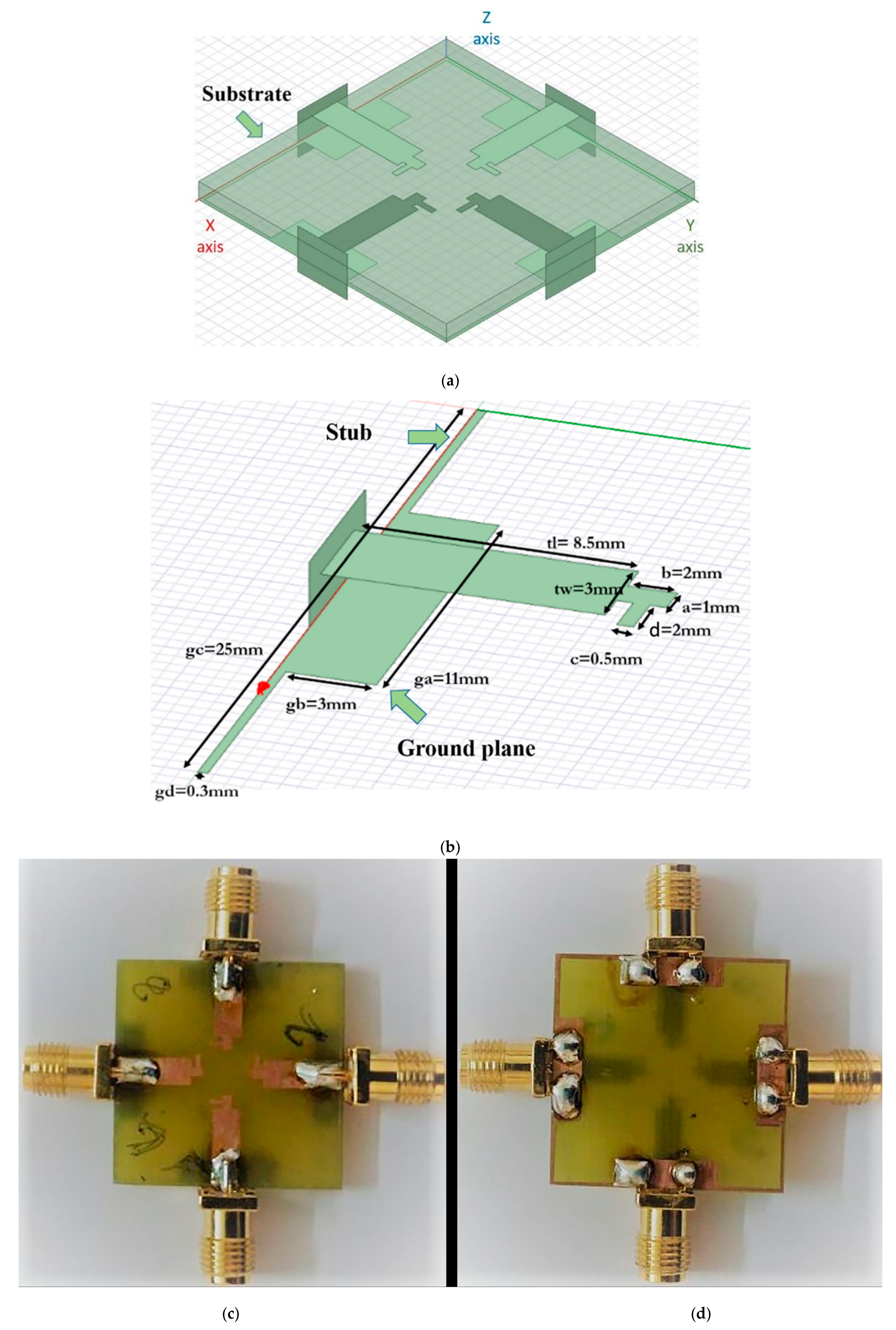
2. Antenna Design and Fabrication
The design diagram of a single-element MIMO antenna is shown in Figure 1. This MIMO antenna is designed on RT/Duroid substrate with relative permittivity of 2.2 and dielectric loss tangent (tanδ) of 0.0009 [26], having a cross-section of 25 mm x 25 mm x 1.6 mm. A microstrip feed line of 50 ohms is utilized to provide the input supply to the antenna.
Figure 1.
(a) Multiple-input multiple-output MIMO antenna with substrate, (b) dimensional geometry of one element in the four-element MIMO antenna, (c) top view of the fabricated antenna, and (d) back view of the ground plane. Substrate is absent in (b) to highlight the ground plane.
The reduced ground plane was designed at the bottom of the substrate and straight stubs of 0.3 mm width are used to establish a connection with the reduced ground plane. Figure 1a shows the MIMO antenna with the substrate understudy in ANSYS HFSS V19.0, and Figure 1b shows the structural parameters of the T-shaped antenna. Initial values of design parameters were a = 1 mm, b = 2 mm, c = 0.5 mm, d = 2 mm, tw = 3 mm, tl = 8.5 mm, ga = 11 mm, gb = 3 mm, gc = 25 mm, and gd = 0.3 mm. Figure 1c,d shows the top and back views of the fabricated MIMO antenna.
Figure 2 shows the simulated and measured return loss of the initial antenna design as shown in Figure 1. The difference between simulated and measured results may be attributed to the fabrication discrepancies and associated tolerances because of the variation of dielectric constant (εr) and loss tangent (tanδ) of the RT/Duroid substrate with frequency and relative humidity [27,28,29].
Figure 2.
Return loss of initial antenna (a) simulated and (b) measured.
A small change in design, relative permittivity, and thickness of substrate were incorporated into our antenna simulation in order to investigate the causes of the difference between the simulated and measured results. Figure 3 shows the modifications made to the antenna design, where the area under the black eclipse represents an area of change, while the red box represents a zoomed-in area. The changes were made in the angle of the patch in the antenna design (to mimic the actual antenna), dielectric constant value to 2.22 from 2.2, and substrate thickness to 1.575 mm from 1.6 mm. All these minor changes resulted in the matching of the losses between the simulated and measured results. However, negligible changes were observed in EMI, radiation pattern, peak gain, and surface current distribution, as shown in Figure 4. Hence, we proceeded with our ideal antenna design instead of the physical antenna design that contained non-ideality.
Figure 3.
Antenna design for (a) modified and (b) initial antenna to match the measurement results. Area under the black eclipse represents an area of change, while the red box represents the zoomed-in area.


Figure 4.
Results for modified antenna (a) return loss, (b) electromagnetic interference (EMI), (c) radiation pattern, (d) peak gain, (e) surface current distribution, and (f) mutual coupling.
3. 2K Factorial
Altering the ten structural parameters helps in reducing EMI, whereas changing the operating frequency affects its area of application [30]. Table 1 shows an example of the different structural parameters that can affect the return loss, bandwidth, and maximum EMI. As full factorial design requires 210 experiments, which is too excessive, fractional 2K factorial was employed [31] with a fraction, which means we can identify the important structural parameters from 32 simulation runs. The maximum and minimum values taken for each parameter are 50% and 150% of their nominal value (shown in Figure 1b). Table 2 provides respective P values for three different responses for which fractional 2K factorials were performed. The P value helps in identifying the importance of the parameters [32].
Table 1.
Examples of the changes in the antenna’s structural parameters on its performance.
Table 2.
List of significant parameters for optimization. None of the interaction terms other than these parameters were found to have P value less than 0.05, hence they are not statistically significant and are not shown here.
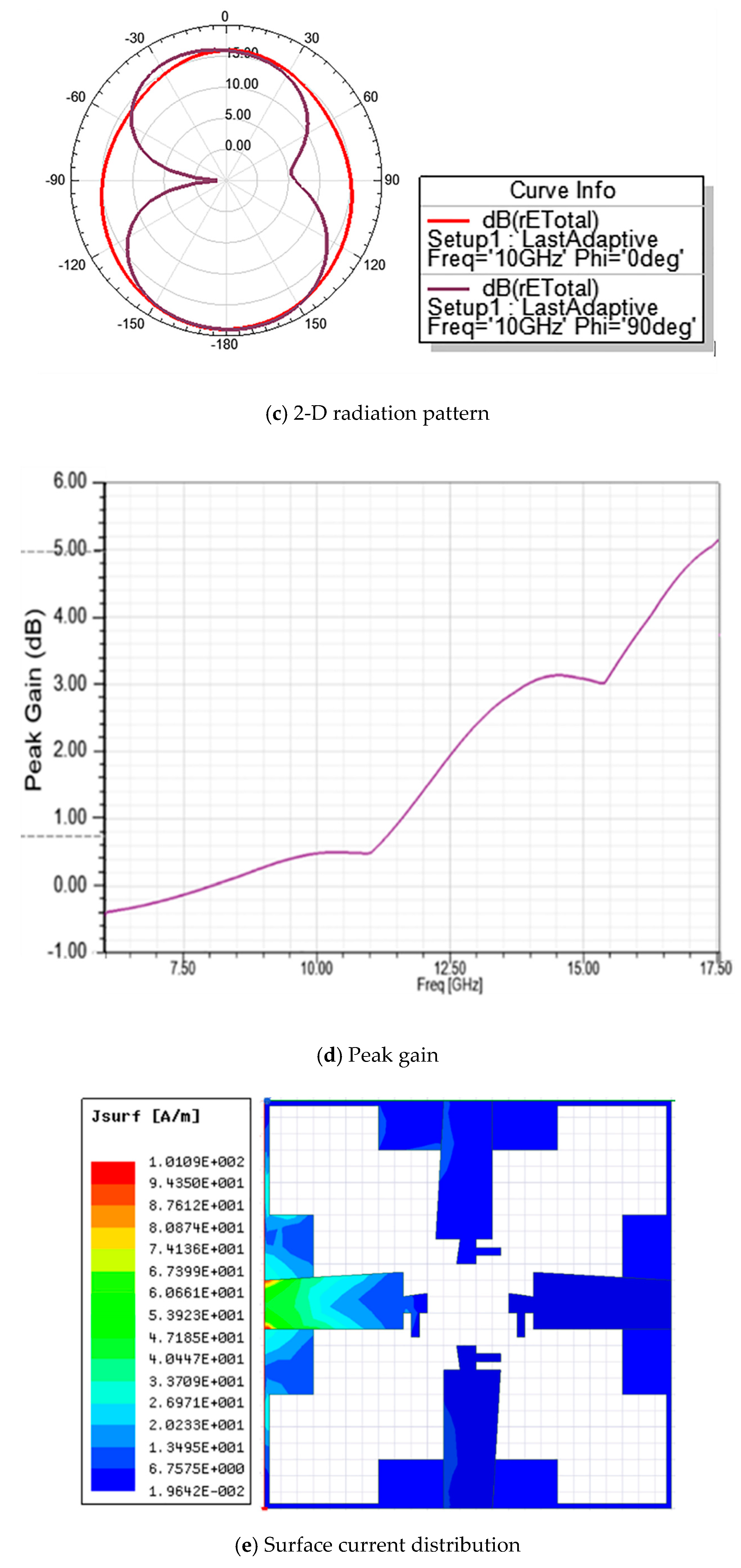
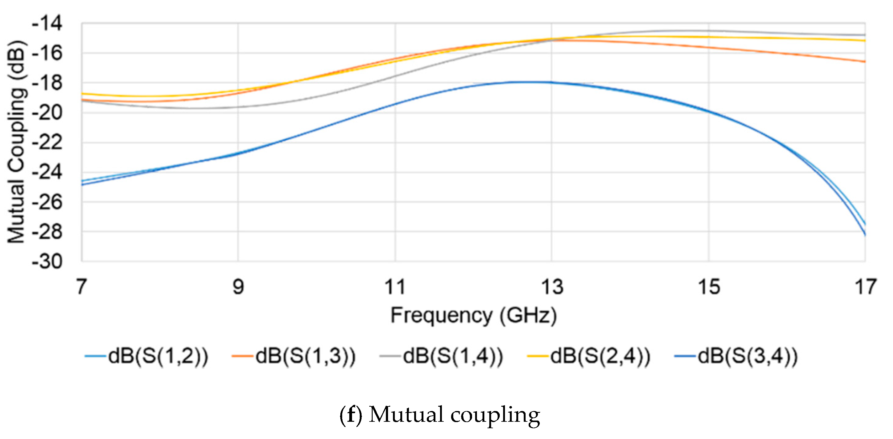
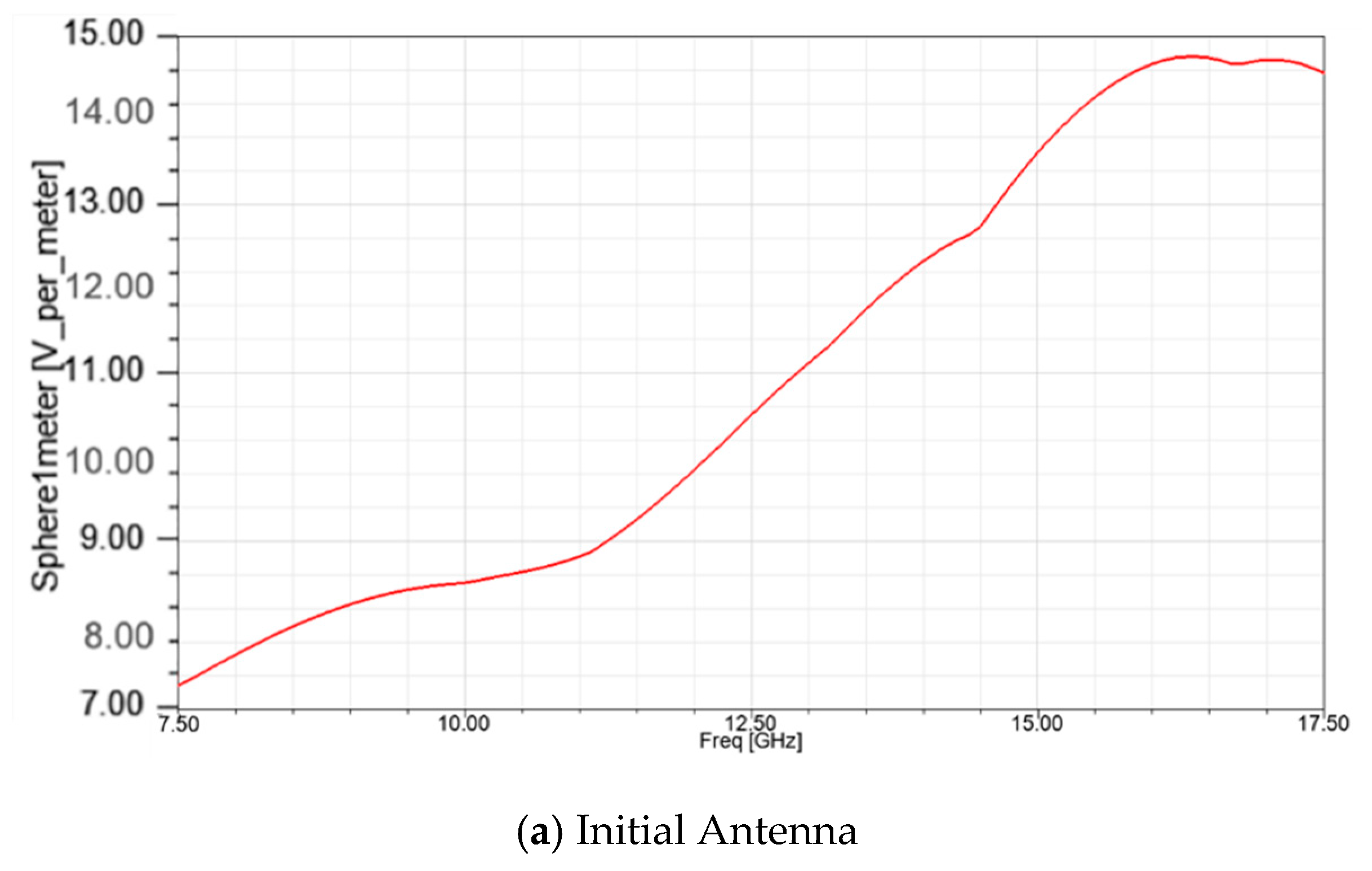
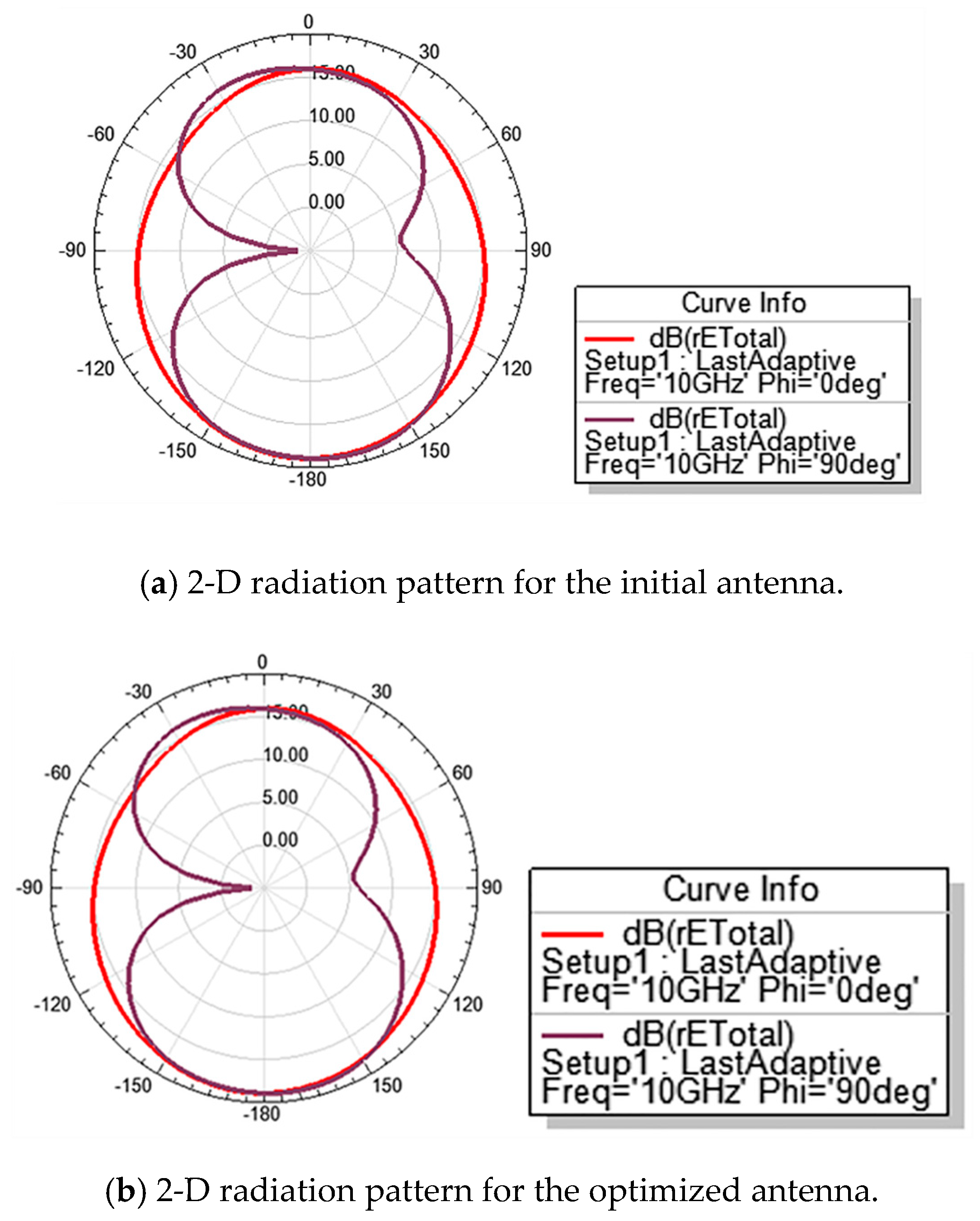
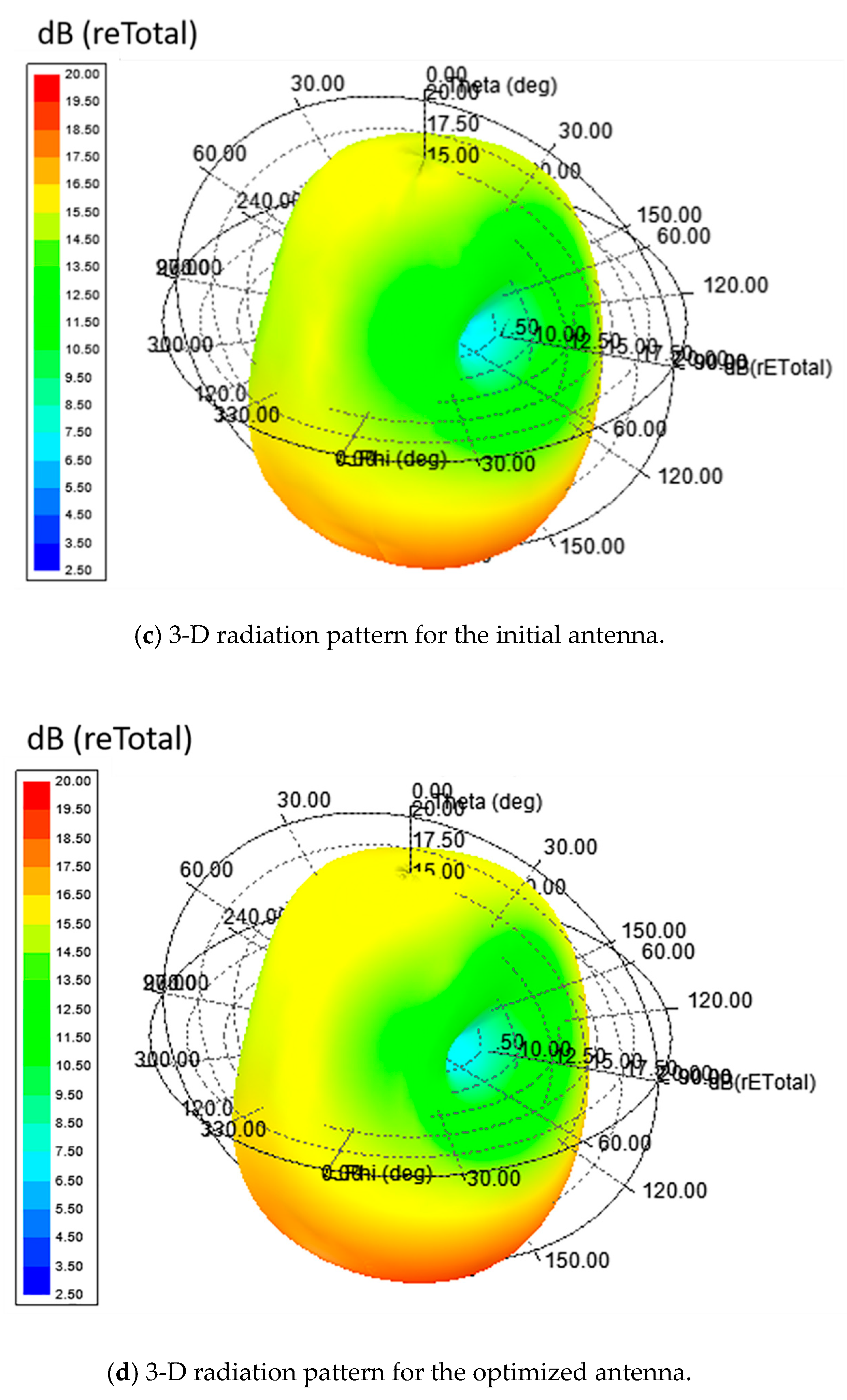
4. Optimization Results and Discussion
After the key structural parameters were identified from the factorial design, GA was employed for optimization. The GA optimizer setup included maximum number of generations (10,000), number of individuals for parents (30), number of mating pools per individual (30), number of individuals for children (30), number of survivors (10), and selection pressure for the next generation (10). For the reproduction setup, a uniform distribution mutation type was utilized with 0.1 uniform mutation probability, 0.5 individual mutation probability, 0.2 variable mutation probability, and 0.05 standard deviation [33]. These GA set up values were taken from [33], which also employed GA to optimize antenna design parameters with highly accurate results.
The optimized values of the parameters are shown in Table 3. Figure 5 shows the optimal design of the antenna in comparison with the initial antenna design.
Table 3.
Initial and optimized values of tl, tw, ga, and gb obtained from the genetic algorithm (GA).
Figure 5.
(a) Initial antenna and (b) optimized antenna, to show the difference in the design.
Figure 6 shows the EMI results for the nominal initial antenna design and the optimized design. We can see that in the frequency range covered by the antenna (shown in Figure 7 where the return loss is less than −10 dB), EMI was reduced by about 1 V/m. The initial antenna design covers a frequency range from 7.84 to 16.44 GHz, while the optimized antenna covers a frequency range from 7.72 to 17.25 GHz In Figure 7, the major change can be seen in the frequency at which the return loss is at a minimum.

Figure 6.
EMI for the 1 m spherical environment from the antenna.
Figure 7.
Return loss of antenna.
The antenna was excited using a wave port excitation at 10.3 GHz frequency and it was observed that the maximum surface current distribution concentrated at the excited port, and this is depicted in Figure 8. Surface current distribution was reduced for the same excitation in the optimized antenna, by almost half of that of the initial antenna. Lower current density points towards lower power consumption of the antenna.
Figure 8.
Surface current distribution.
The 2-D and 3-D radiation patterns obtained in the E-fields and H-fields of the initial and optimized antennas at 10 GHz (operating frequency) was simulated and depicted in Figure 9. The antenna was simulated in the xz-plane orientation, where red and violet color patterns in Figure 9a and b represent radiation patterns for phi angles of 0° and 90°, respectively, and the theta angle is 0°. 3-D radiation patterns help to study the spread from the antenna into the environment. It is noticed that both the initial and optimized antennas achieved omnidirectional radiation patterns at a central frequency.

Figure 9.
Radiation patterns for the initial and optimized antennas: (a,b) show 2-D radiation patterns and (c,d) show 3-D radiation patterns.
Peak gain was plotted with respect to the operating frequency of the antenna as shown in Figure 10. An increase in peak gain was observed with the increase in operating frequency: 0.7 dB to 4.95 dB was the average peak gain of the initial antenna design, whereas 0 dB to 5 dB was the average peak gain for the optimized antenna for the given frequency range (where return loss was less than −10 dB). The advantage of stubs is that it helps to achieve small peak gains at lower operating frequencies [34]. A small variation of 0.05 dB found in the peak gain of an antenna is because of the reduced ground plane [34].
Figure 10.
Peak gain in dB for initial and optimized antenna designs.
Mutual coupling between ports for the initial (found to be < −15 dB) and optimized antennas (found to be < −12 dB) are shown in Figure 11. Higher isolation was observed for ports 1 to 2 and 3 to 4 due to the identical structure of elements. The peak values of the isolation (within the obtained band) were −22 dB and −21.24 dB for the initial and optimized antennas, respectively, at 10.3 GHz. Thus, the isolation was sufficiently good with the optimized antenna. Table 4 represent the difference between initial and optimized antenna parameters.
Figure 11.
S-parameters of the MIMO antenna for mutual coupling between ports for (a) the initial antenna and (b) the optimized antenna.
Table 4.
Antenna parameter values for the initial and optimized antennas.
5. Conclusions
In this paper, a miniaturized single element of a T-shaped MIMO antenna was designed, optimized, and simulated. The 2K factorial and genetic algorithm optimization techniques were used for the optimization of the antenna. It was found that gb, ga, tl, and tw, as defined in Figure 1, were the major dimensional parameters affecting the return loss, peak gain, bandwidth, radiation pattern, surface current distribution, and EMI of the antenna. The optimized antenna had a wider frequency band that ranged from 7.72 to 17.25 GHz. This corresponded to a 1 GHz improvement in the bandwidth due to the improved return loss that provides new opportunities for the antenna’s utilization in different applications. The optimized antenna had lower current distribution that gives lower power dissipation and its 1 m sphere EMI was also reduced.
Author Contributions
Conceptualization, C.M.T.; methodology, D.K.; software, D.K., V.S., V.P., N.T.; validation, D.K.; formal analysis, D.K., V.S., V.P.; investigation, D.K.; resources, C.M.T.; data curation, D.K., V.S., V.P.; writing—original draft preparation, D.K.; writing—review and editing, C.M.T.; visualization, D.K., N.T.; supervision, C.M.T.; project administration, C.M.T.; funding acquisition, C.M.T. All authors have read and agreed to the published version of the manuscript.
Funding
This work was funded by the Chang Gung University research Grants QZRPD123 and CIRPD2F0024.
Conflicts of Interest
The authors declare no conflict of interest.
References
- Kragalott, M.; Kluskens, M.S.; Zolnick, D.A.; Dorsey, W.M.; Valenzi, J.A. A toolset independent hybrid method for calculating antenna coupling. IEEE Trans. Antennas Propag. 2011, 59, 443–451. [Google Scholar] [CrossRef]
- Saxena, S.; Kanaujia, B.K.; Dwari, S.; Kumar, S.; Tiwari, R. A Compact Dual-Polarized MIMO Antenna with Distinct Diversity Performance for UWB Applications. IEEE Antennas Wirel. Propag. Lett. 2017, 16, 3096–3099. [Google Scholar] [CrossRef]
- Rajkumar, S.; Vivek Sivaraman, N.; Murali, S.; Selvan, K.T. Heptaband swastik arm antenna for MIMO applications. IET Microw. Antennas Propag. 2017, 11, 1255–1261. [Google Scholar] [CrossRef]
- Roshna, T.K.; Deepak, U.; Sajitha, V.R.; Vasudevan, K.; Mohanan, P. A compact UWB MIMO antenna with reflector to enhance isolation. IEEE Trans. Antennas Propag. 2015, 63, 1873–1877. [Google Scholar] [CrossRef]
- Krishna, R.V.S.R.; Kumar, R. A Dual-Polarized Square-Ring Slot Antenna for UWB, Imaging, and Radar Applications. IEEE Antennas Wirel. Propag. Lett. 2016, 15, 195–198. [Google Scholar] [CrossRef]
- Jafri, S.I.; Saleem, R.; Shafique, M.F.; Brown, A.K. Compact reconfigurable multiple-input-multiple-output antenna for ultra wideband applications. IET Microw. Antennas Propag. 2016, 10, 413–419. [Google Scholar] [CrossRef]
- Khan, A.A.; Jamaluddin, M.H.; Aqeel, S.; Nasir, J.; Kazim, J.U.R.; Owais, O. Dual-band MIMO dielectric resonator antenna for WiMAX/WLAN applications. IET Microw. Antennas Propag. 2017, 11, 113–120. [Google Scholar] [CrossRef]
- Iqbal, A.; Saraereh, O.A.; Ahmad, A.W.; Bashir, S. Mutual Coupling Reduction Using F-Shaped Stubs in UWB-MIMO Antenna. IEEE Access 2017, 6, 2755–2759. [Google Scholar] [CrossRef]
- Tian, R.; Lau, B.K.; Ying, Z. Multiplexing efficiency of MIMO antennas. IEEE Antennas Wirel. Propag. Lett. 2011, 10, 183–186. [Google Scholar] [CrossRef]
- Liu, X.; Bialkowski, M.E. Effect of antenna mutual coupling on MIMO channel estimation and capacity. Int. J. Antennas Propag. 2010, 2010, 1–9. [Google Scholar] [CrossRef]
- Abdul Haleem, M. On the capacity and transmission techniques of massive MIMO Systems. Wirel. Commun. Mob. Comput. 2018, 2018, 1–9. [Google Scholar] [CrossRef]
- Khalighi, M.A.; Raoof, K.; Jourdain, G. Capacity of wireless communication systems employing antenna arrays, a tutorial study. Wirel. Pers. Commun. 2002, 23, 321–352. [Google Scholar] [CrossRef]
- Du, J.; Li, Y. Optimization of antenna configuration for MIMO systems. IEEE Trans. Commun. 2005, 53, 1451–1454. [Google Scholar] [CrossRef]
- Kiehbadroudinezhad, S.; Noordin, N.K.; Sali, A.; Abidin, Z.Z. Optimization of an antenna array using genetic algorithms. Astron. J. 2014, 147, 1–13. [Google Scholar] [CrossRef]
- Telzhensky, N.; Leviatan, Y. Novel method of UWB antenna optimization for specified input signal forms by means of genetic algorithm. IEEE Trans. Antennas Propag. 2006, 54, 2216–2225. [Google Scholar] [CrossRef]
- Binitha, S.; Siva Sathya, S. A survey of bio inspired optimization algorithms. Int. J. Soft Comput. Eng. 2012, 2, 137–151. [Google Scholar]
- Hussein, A.H.; Abdullah, H.H.; Salem, A.M.; Khamis, S.; Nasr, M. Optimum design of linear antenna arrays using a hybrid MoM/GA algorithm. IEEE Antennas Wirel. Propag. Lett. 2011, 10, 1232–1235. [Google Scholar] [CrossRef]
- Zhou, D.; Abd-Alhameed, R.A.; See, C.H.; Bin-Melha, M.S.; Zainal-Abdin, Z.B.; Excell, P.S. New antenna designs for wideband harmonic suppression using adaptive surface meshing and genetic algorithms. IET Microw. Antennas Propag. 2011, 5, 1054–1061. [Google Scholar] [CrossRef]
- Robinson, J.; Rahmat-Samii, Y. Particle swarm optimization in electromagnetics. IEEE Trans. Antennas Propag. 2004, 52, 397–407. [Google Scholar] [CrossRef]
- Mohammed, H.J.; Abdullah, A.S.; Ali, R.S.; Abd-Alhameed, R.A.; Abdulraheem, Y.I.; Noras, J.M. Design of a uniplanar printed triple band-rejected ultra-wideband antenna using particle swarm optimisation and the firefly algorithm. IET Microw. Antennas Propag. 2016, 10, 31–37. [Google Scholar] [CrossRef]
- Johnson, J.M.; Rahmat-Samii, Y. Genetic algorithms in engineering electromagnetics. IEEE Antennas Propag. Mag. 1997, 39, 7–21. [Google Scholar] [CrossRef]
- Panduro, M.A.; Brizuela, C.A. A comparative analysis of the performance of GA, PSO and DE for circular antenna arrays. In Proceedings of the IEEE Antennas and Propagation Society International Symposium, Charleston, SC, USA, 1–5 June 2009; IEEE: Piscataway, NJ, USA, 2009; pp. 1–4. [Google Scholar]
- Binelo, M.O.; De Almeida, A.L.F.; Cavalcanti, F.R.P. MIMO array capacity optimization using a genetic algorithm. IEEE Trans. Veh. Technol. 2011, 60, 2471–2481. [Google Scholar] [CrossRef]
- Oprime, P.C.; Pureza, V.M.M.; De Oliveira, S.C. Systematic sequencing of factorial experiments as an alternative to the random order. Gest. Prod. 2017, 24, 108–122. [Google Scholar] [CrossRef]
- Cavalcanti, F.R.P. Resource Allocation and MIMO for 4G and Beyond; Springer: New York, NY, USA, 2014. [Google Scholar]
- E Silva Neto, A.S.; de Macedo Dantas, M.L.; dos Santos Silva, J.; César Chaves Fernandes, H. Antenna for fifth generation (5G) using a EBG structure. In New Contributions in Information Systems and Technologies; Springer: Cham, Switzerland, 2015; pp. 33–38. [Google Scholar]
- Hoang, T.V.; Le, T.T.; Li, Q.Y.; Park, H.C. Quad-Band Circularly Polarized Antenna for 2.4/5.3/5.8-GHz WLAN and 3.5-GHz WiMAX Applications. IEEE Antennas Propag. Lett. 2016, 15, 1032–1035. [Google Scholar] [CrossRef]
- Liu, X.L.; Wang, Z.D.; Yin, Y.Z.; Ren, J.; Wu, J.J. A compact ultrawideband MIMO antenna using QSCA for high isolation. IEEE Antennas Wirel. Propag. Lett. 2014, 13, 1497–1500. [Google Scholar] [CrossRef]
- Tang, T.C.; Lin, K.H. An ultrawideband MIMO antenna with dual band-notched function. IEEE Antennas Wirel. Propag. Lett. 2014, 13, 1076–1079. [Google Scholar] [CrossRef]
- Kishk, A. Advancement in Microstrip Antennas with Recent Applications; InTech: Rijeka, Croatia, 2013. [Google Scholar]
- Hilow, H. Minimum cost linear trend free fractional factorial designs. J. Stat. Theory Pract. 2012, 6, 580–589. [Google Scholar] [CrossRef]
- Dahiru, T. P-Value, a true test of statistical significance? A cautionary note. Ann. Ibadan Postgrad. Med. 2008, 6, 21–26. [Google Scholar] [CrossRef]
- Mohammed, H.J.; Abdulsalam, F.; Abdulla, A.S.; Ali, R.S.; Abd-Alhameed, R.A.; Noras, J.M.; Abdulraheem, Y.I.; Ali, A.; Rodriguez, J.; Abdalla, A.M. Evaluation of genetic algorithms, particle swarm optimisation, and firefly algorithms in antenna design. In Proceedings of the 2016 13th International Conference on Synthesis, Modeling, Analysis and Simulation Methods and Applications to Circuit Design, SMACD 2016, Lisbon, Portugal, 27–30 June 2016; IEEE: Piscataway, NJ, USA, 2016; pp. 1–4. [Google Scholar]
- John, M.; Evans, J.A.; Ammann, M.J.; Modro, J.C.; Chen, Z.N. Reduction of ground-plane-dependent effects on microstrip-fed printed rectangular monopoles. IET Microw. Antennas Propag. 2008, 2, 42–47. [Google Scholar] [CrossRef]
© 2020 by the authors. Licensee MDPI, Basel, Switzerland. This article is an open access article distributed under the terms and conditions of the Creative Commons Attribution (CC BY) license (http://creativecommons.org/licenses/by/4.0/).


