1. Introduction
The environmental impact of commercial construction and fabrication methods has been well documented. The built environment, for instance, accounts for 36% of global energy use, with cement alone contributing to 8% of annual global carbon dioxide production [
1,
2,
3].
The creation of complex forms, be it a wall or a chair, can become an especially resource-intensive exercise. This expense is not only in terms of the embodied energy of the artefact itself but also the process required to produce it. This often occurs when materials are deployed in a simple, homogenous, top-down manner. This is not a new problem, nor is it trivial, and there are a number of attitudes for using materials more responsibly. Some strategies come from incremental technological development, whilst others adopt techniques, technologies, and ideas from other industries, opening the door to new possibilities [
4]. It is appropriate, then, to investigate how these alternative approaches may translate into more harmonious architectural design solutions.
Fiber-reinforced composites (FRCs) have been well used in the automotive, nautical, and aerospace industries over the last decades, but less so in architecture and product design. In contrast to some other processes, working with composites can allow for the strategic placement of material to create differentiated structure and geometry. This is typically done in an additive process and can result in products with a high specific strength. A superior strength-to-weight ratio can, in turn, translate into reduced material use, as well as reduced use of supporting materials, such as concrete or metals [
5].
Two particularly novel composite fabrication methods for FRCs are coreless filament winding (CFW) and tailored fiber placement (TFP). Both processes have great potential at the architectural scale. These techniques deploy numerically-controlled machines in digital design workflows for precision, efficiency, and mass-customization [
6,
7]. However, both CFW and TFP still used complicated and resource-intensive fabrication frames or molds during production (
Figure 1).
For almost 10 years, the Institute for Computational Design (ICD), the Institute of Building Structures and Structural Design (ITKE), and, more recently, the BioMat group at ITKE (the Department of Biobased Materials and Materials Cycles in Architecture) at the University of Stuttgart, have investigated composites through the lenses of computation, digital design and fabrication, structure, and sustainability. Their research has not been limited to conventional FRC based on carbon fibers (CFs) and glass fibers (GFs), but also explored possibilities of replacing them with fibers from annually renewable resources, such as flax and hemp, as well as with agricultural residues, namely straw, for the purpose of developing structural systems based on natural fiber-reinforced polymers (NFRPs) [
8]. Through a multifarious series of temporary pavilions, demonstrators, seminars, and research projects, the potential of these materials at an architectural scale have been investigated [
5,
6]. This project dives deeper into this research context, building on the pioneering work of these institutes. The corresponding precedent projects shown below should additionally be understood through the broader goal of this project and the design and prototyping of a stool.
In their project “Tailoring Self-Formations”, Aldinger and Margariti explored carbon fiber bending elements sewn onto a prestressed membrane substrate (
Figure 2a). The self-formation process was driven by the release of the prestress in the membrane, which in turn acted as an actuator. The actuation sent the CFP elements into bending, determined by specific predefined 2D geometries, thereby predictably creating complex double-curved surfaces without the need for a mold. This project illustrates the possibility of creating complex forms in mold-less TFP fabrication, as well as fiber-reinforced composites (FRCs) in bent states of compound Gaussian curvature [
10].
The ICD/ITKE Research Pavilion 2016–17 is a good precedent of a biomimetic transfer for an embedded bending active filament winding frame (
Figure 2b). In this case, the biological role model was the leaf miner moth (
Lyonetia clerkella), which bends a leaf into shape with its silk and then uses the resulting geometry as the environment to create a cocoon. The abstracted fabrication process starts with a flat CFW preform, which is bent into shape, becoming the winding scaffold for the main layers of structural filaments of the demonstrator. In this case, the ratio of the winding frame to the CFW component was minimal. Additionally, a substantial portion of the fabrication setup remained embedded within the structure, taking on an additional function [
11].
In 2019, BioMat successfully attempted to realize a small scale monolithic NFRP canopy using TFP preforms for precise control of fiber orientation in the structure (
Figure 2c). Rhinoceros 3D plugins (Grasshopper, Galapagos and Millipede) used in the initial form-finding process of this lightweight canopy allowed us to define the most deformation-resistant geometry. Further topological optimization of the structure was conducted using Matlab and an agent-based system tool created using processing. This allowed us to calculate the optimum flax fiber paths orientation on the whole structure surface to be realized at a later TFP fabrication stage. Secondly, the structure was tessellated into several overlapping layers consisting of multiple preforms no larger than 1.0 x 1.4 m. This size limitation was imposed by the working area of the Tajima TFP embroidery machine, offered by the Institute of Aircraft Design (IFB) at the University of Stuttgart. Finally, all preforms were placed on a mold, custom-made using CNC-milled elements, for a vacuum-assisted resin transfer molding (VARTM) process [
12]. A tailored biocomposite mock-up of BioMat 2019 proved the applicability of TFP fabrication in structural projects requiring topological optimization. However, at the same time, it exposed the necessity of developing alternative, more resource-efficient solutions to complex 3D molds used in the VARTM process.
Finally, Duque Estrada and Wyller investigated design methodologies for CFW of carbon fiber for ultra-lightweight furniture design (
Figure 2d). Their “Aerochair” used the high tensile strength of carbon rovings as the primary design driver. “By allowing the chair to hang, instead of stand, a new design expression that properly conveys the material characteristics presents itself” [
13]. This project successfully demonstrates the use of continuous resin-impregnated carbon fiber yarns, with the furniture piece weighing only 300 g. However, the fabrication process still requires a large and complex frame. Furthermore, the novel hanging typology may not be a fully representative portrayal of a load-bearing architectural system, which must typically accommodate compression and bending in addition to tension. Consequently, there still remains significant terrain for further investigation.
Therefore, the aim of this project was to create a stool with coreless filament winding and tailored fiber placement of resin-impregnated, continuous natural fiber yarn without the use of a complicated mold or frame. The design and physical production of a small furniture piece was used as a means to engage the research context beyond just the theoretical level. A small-scale demonstrator, in other words, facilitates practical access to the architectural function (ergonomics, scale etc.) and structural performance (strength, weight etc.), as well as the realities of fabrication, implementation, and the myriad of small design challenges that emerged during the prototyping process. The investigation was undertaken through a bespoke design-to-production system, comprising three conceptual stages; “Stitch”, “Bend”, and “Weave” (
Figure 3).
In this experimental approach, the selection of sustainable structural materials and fabrication methods took place before the step of defining the actual architectural design of a piece. In this case, applying the principles of “Materials as a Design Tool” philosophy [
14] allowed for unrestricted shaping of the spatial form of the prototype, with particular focus on efficient use of fibrous composite material in an additive fabrication process, allowing for a reduction in the amount of production residues and eliminating the necessity of using disposable moulds made in subtractive fabrication processes such as CNC-milling.
2. Materials and Methods
2.1. Flax Fibre and Epoxy Resin
Research on natural fibers is a field of growing interest within the realm of the composites industry, primarily due to their production from annually renewable resources in low energy-intensive processes and their inherent potential for biodegradability and recycling at end of life; aspects which their synthetic counterparts cannot yet address as effectively at the time of writing [
15,
16,
17,
18]. This project builds upon the current trend as a means of establishing a viable structural application. As a result, non-twisted flax fiber rovings in two linear densities, 1200 Tex and 2400 Tex, have been selected for all production methods at the prototyping stage and sourced from the distributor, Group Depestele (Teillage Vandecandelaere 5, rue de l’église, 14 540 Bourguebus, France).
Although equivalent research may be found with respect to biodegradable polymer matrices, material explorations were limited to only the fiber component of the composite. Fully synthetic Epoxy Resins (3 parts EPIKOTE Resin MGS RIMR 235 + 1 part EPIKURE Curing Agent RIMH 237, Pot Life: 48 h, all produced by Hexion Inc. and provided by Hexion Stuttgart GmbH, Fritz-Müller-Straße 114, 73730 Esslingen am Neckar, Germany) were therefore selected as the base matrix, due to prior experience with the products.
2.2. Deductive Methodology
The investigations detailed in this paper build upon the previously outlined case studies with respect to production techniques of fibrous composites and product design. The project consequently utilizes a deductive research method to assess whether the addition of TFP with CFW techniques can unlock further avenues for fibrous composites via the moldless design and production of a stool. This hypothesis is further broken down into sub-investigations, pertaining to each production method respectively.
2.3. Design Process
The physical design was developed in an iterative bottom-up process that overlaps material, fabrication, and global design investigations. Initial explorations began with rapid modelling of scaled paper models to establish global geometry. This was subsequently coupled with full scale material tests, the principles of which were extracted from pre-existing literature, such as the lamination theory [
19,
20]. These tests investigated localized performance, such as bending or stiffness, which were then extrapolated to the overall global geometry of the stool (
Figure 4). These elements were then synthesized into a consolidated design prototype and tested for performance and function. The findings from each iteration were then interrogated, explored, and developed in subsequent versions of the design. Collectively, this formed an integrative design feedback loop.
The main structural criteria that needed to be met by the design was to sustain the weight of a person inducing a load of minimum 800 N. Final testing of the prototype was conducted by the authors.
2.4. Production Process
The production process was divided into two main parts; the manufacture of a bendable scaffold, produced flat and bent into shape using a custom rig (previously conceptualized as “Stitch” and “Bend”) and the reinforcement of the scaffold via fiber winding to sustain the design load (termed “Weave”). Both parts were characterized by the use of the TFP and CFW processes, respectively, and detailed further below.
2.5. Tailored Fiber Placement
The TFP process makes use of an industrial grade embroidery machine that continuously lays filament material upon a thin, stretched textile mounted on a 2D movable frame [
19]. In this project, dry, non-impregnated flax roving was laid using a 4-head embroidery machine of the brand Tajima, provided through the courtesy of Institute of Aircraft Design (IFB) at the University of Stuttgart. Filament material was also prepared by being spun in small quantities over a spool attached to the head of the machine. As fibers were laid down onto the textile, a fixed sewing needle and bobbin secured the fibers in place via a second threaded spool. The automated textile frame was numerically controlled and digitally programmed to follow any given path that was fed as a continuous polyline. In this project, a file with fiber path polylines was generated using CAD software Rhinoceros 3D. Moreover, primary fabrication parameters of the TFP process included the “stitch length” and “stitch width” of the thread, which collectively influenced the resolution of the final laid pattern. Exact values for these parameters were adjusted during prototyping and tabulated accordingly in the results section. Topological optimization in solidworks was used to inform the distribution of fibers along the designed preform.
The nature of this machine allowed an infinite set of customizable patterns to be made on a 2D surface (
Figure 5a). In this context, a first sub-hypothesis is formulated as to whether tailored orientation of fibers in a cured state can allow for a controlled ability to bend a surface and achieve specific geometries.
2.6. Coreless Filament Winding
CFW entails winding a continuous resin-impregnated filament material over a scaffold, typically via robotic automation. Due to the anisotropic nature of fibrous composites, an understanding of force flow in components becomes crucial to the fiber layup design. This pattern, termed “syntax”, refers specifically to the sequence in which the continuous fiber is wound. Consequently, it can allow for a localized differentiation in material count, resistance to buckling failure, and varied geometry [
9,
21]. Since loading conditions for a small scale product design provide a simplified testing environment, stress flows and syntax design for the stool were set up empirically. The small scale also eliminated the need for robotic automation. Instead, the winding procedure for prototyping was carried out manually (
Figure 5b).
This CFW technique relies heavily on keeping fibers taut upon the scaffold for maximum fiber–fiber interaction and performance [
21,
22], consequently placing additional pressures on the scaffold’s stiffness. A second sub-hypothesis here questions whether such a technique can be used to permanently reinforce the 2D bent geometries generated via TFP methods.
2.7. Fibre Impregnation Methods
The mechanical properties of fiber composites are heavily influenced by the matrix-to-reinforcement ratio and the corresponding interface [
23]. Due to a need for repeatable prototyping and controlled bending stiffness of the TFP surface, a reliable fiber impregnation method became necessary. A vacuum infusion process was consequently adopted to minimize behavioral discrepancies stemming from production. In this process, dry TFP preforms were manually infused with resin and subsequently sealed in an airtight bag. A negative pressure was applied by means of a vacuum pump, causing the resin to disperse evenly throughout the TFP preform and drain any excess material away from the sample. Upon full infusion, the sample was removed from the bag and left to cure.
For CFW, the fibers were continuously passed through a custom-built resin bath in order to absorb sufficient resin throughout the winding process, as shown in
Figure 6 Upon completion, full curing took place and the prototype was demounted from the clamping rig.
2.8. Analysis Criteria
As a means to benchmark the prototyped outcomes, functional and performative criteria were restricted to three design conditions:
Ability to sustain the 800 N design load;
Minimalization of total weight of stool and corresponding material usage;
Qualitative comfort enabled by the geometry;
These conditions, coupled with design development, were tested, verified, and presented in further detail in the following sections as a means of validating the initial hypothesis.
3. Results
Performing the production process at the Institute of Aircraft Design (IFB) at the University of Stuttgart provided opportunities for interdisciplinary cross-pollination, where valuable insights were gained from the engineers. The TFP machine was used to produce a series of material test preforms and a first prototype to engage with the complexities of the machine and the specific data protocols required for production. After that, a final iteration was produced (
Figure 7), which is the focus of this Results section. The final iteration was informed by these previous tests and addressed specific challenges of topological optimization, the TFP process, filament winding, and performance. Although somewhat independent, the integrated nature of the design and fabrication method meant that these elements were interrelated.
3.1. Topological Optimization
To better inform the placement of fibers in the TFP preform, the topological optimization platform in solidworks was used.
A simplified topology study tool was used to provide a rough visual estimation as to how the stresses distribute along the surface. The results allowed for a diagrammatic visualization of where the bulk of the material would be required for a given load configuration. Different amounts of material reduction were investigated for the same load case and edge condition. A selection of these studies can be seen in
Figure 8.
For the topology study, an 8 mm thick single curved surface, modelled in Rhino3D, was prepared and imported accordingly. The specified surface thickness was imposed by the fabrication limitations of the Tajima embroidery machine used at the fabrication stage. The filament winding syntax was omitted from the simulation. As the exact mechanical properties of the used combination of flax roving and resin were difficult to pinpoint and were not available at the specific moment of conducting the fabrication experiment, the simulation was run using the built-in properties of glass fiber, providing that the desired stiffness criteria could be reached when lower mechanical strength of flax fiber in comparison to glass fiber was compensated by using sufficiently higher volume fractions [
24].
An evenly distributed load of 800 N was applied to its horizontal seating surface. Winding pins were defined as a fabrication constraint, which forced the software to preserve the geometry during optimization.
The simulation was run using the best mass-to-stiffness goal criteria, for which various percentages, ranging from 30% to 70%, were studied. No distinct outcome was favored. Instead, the simulations, all of which delivered similar results (such as in the associated figure), were used comparatively to identify the crucial areas transferring higher forces and thus requiring more material to be deployed.
Regions in yellow indicate places where material was needed most and those in blue indicate where material was needed the least. Throughout the iterations, it was possible to notice the emergence of a Y-shape distribution of material on the legs, which suggested that these areas had the biggest fiber cross-sections, i.e., structural layers. It was also possible to conclude that the seat area needed to remain dense. Other areas of the initial input surface were excluded, generating a new edge condition for the final design. Finally, this simulation did not provide the definitive visual pattern of the surface, but rather guided the TFP surface design.
3.2. TFP Process
3.2.1. TFP Pattern
In order to determine the fiber path pattern in the final TFP preform, with particular focus on enabling the flexible behavior of the bending zones, the anisotropic nature of the fibrous composite material required combining the results of the above-mentioned simplified optimization process with an interpretation of classical lamination theory (CLT) [
17,
18].
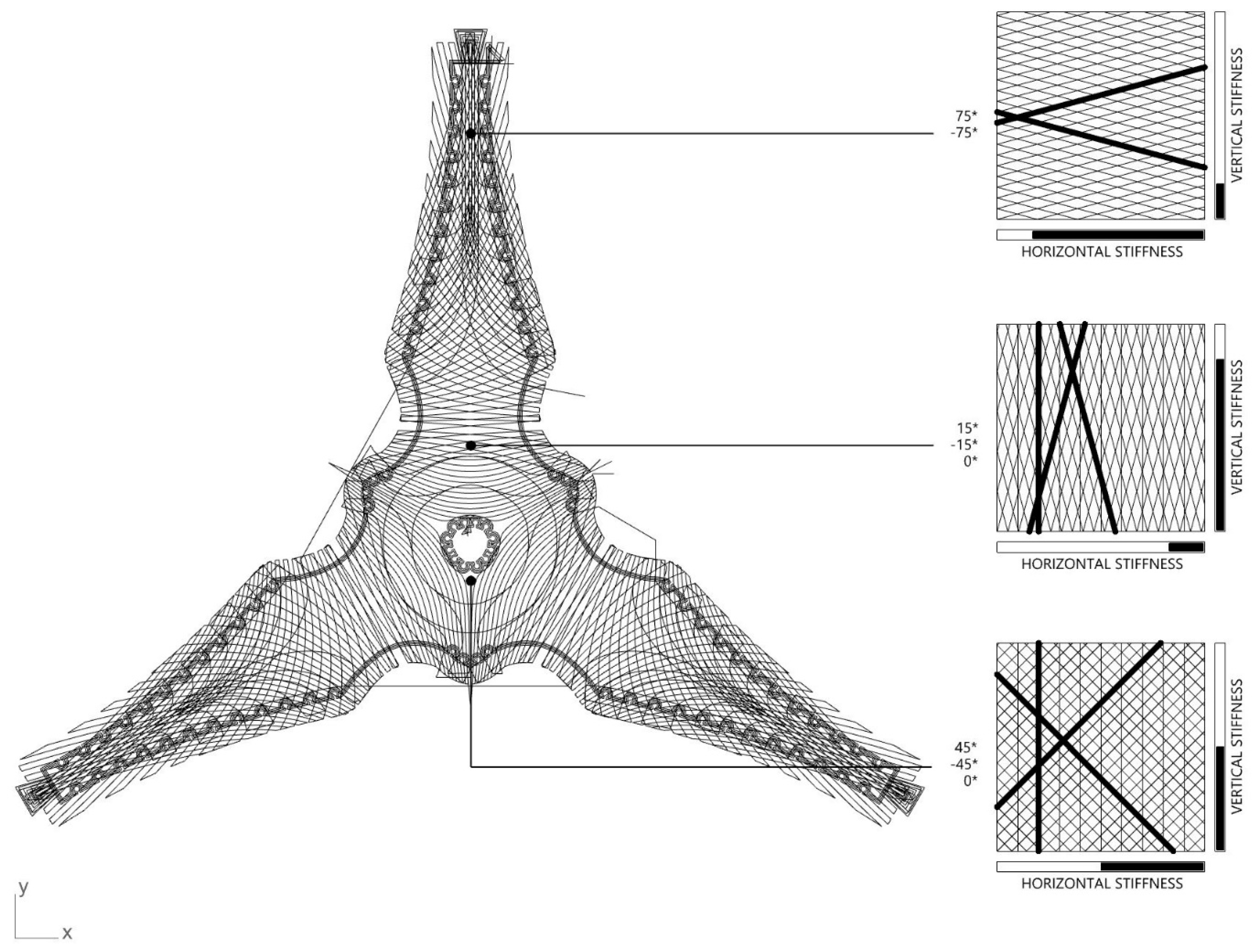
The finished TFP preform, after resin infusion process and complete curing, was supposed to be formed into a single curved surface and serve as the integrated frame in a later winding process. This required planning a diversified fiber path layout, which would reinforce and stiffen the seating area and leg endings, while guaranteeing a necessary flexibility of the composite material in the areas where the TFP preform was supposed to be bend (
Figure 9).
Consequently, fiber paths in the seating area, oriented at −45°, 0°, and 45°, aim at creating a quasi-isotropic layup sequence, resulting in constant stiffness of the material regardless of the force direction, yet offering minimal elasticity of the surface for the purpose of seating comfort. Starting from the leg tips, in the leg areas, fiber paths were oriented, at −75° and 75°, thus almost parallel to the leg axis, in order to use material properties to the maximum when trying to develop a stiff structure that would not deflect under load. However, the closer to the hinge area, the more the fiber path angles smoothly translated to more perpendicular orientation, reaching −15° and 15° in the center of the hinge areas.
Secondly, this core fiber path topology, designed according to structural performance of the stool model, was complemented with additional paths, which constituted further reinforcement and design details needed at a later stage of fiber winding.
The complete design of the fiber paths in the final TFP preform structure had to be adjusted to the fabrication requirements of the machine. Thus, according to the role each fiber path fragment played in both in the fabrication process, as well as later in the structural performance of the stool, they were grouped into three layers, which were fabricated consecutively one on top of the other, using 1200 TEX and 2400 TEX flax fibers by the embroidery machine.
The final TFP pattern consisted of three layers:
This layer was of special importance, since it provided the interface for the CFW process. The challenge at this step was determining the appropriate size of the pins. In order to guarantee visual integration of the pins in the final design of the FlexFlax, their dimensions should remain as modest as possible, but, at the same time, should be above the minimum fabrication size requirements of the TFP machine. The chosen geometry was a trapezoid of 2 cm (long base), 1 cm (short base), and 2 cm (height). To provide a delicate cross-section, a TFP machine preset of 1.5mm stitch width was used for 1200 Tex flax fiber rovings. To guarantee the resolution of the winding pins, a 1 mm stitch length was set. Consequently, flax roving was sewn to the substrate with a higher number of stitches. However, this compromise resulted in a significantly longer production time for this stage of the TFP process.
The surface layer, containing the fiber layout for the bending zone, was formed from 1200 Tex Flax roving with a stitch width of 1.5 mm and a stitch length of 7 mm.
The structural layer was fabricated using 2400 Tex roving, with a cross-sectional dimension of 3.6 mm (stitch width). In this final layer, a boundary curve was embedded in order to reinforce the thinner rovings during the fabrication process. The final TFP pattern was sewn into a cotton substrate of 1000 × 1400 mm. The used TFP machine settings, as well as the resulting fiber lengths for each layer, are presented in
Table 1.
3.2.2. Vacuum Infusion
After the accomplished TFP fabrication of the preforms, the excess of the substrate fabric was trimmed, and resin was applied through the vacuum infusion process explained in
Section 2.7. The used resin system was EPIKOTE Resin MGS RIMR 235 with EPIKURE Curing Agent RIMH 237, produced by Hexion Inc. Standard polythene vacuum bags of 130 × 90 mm, commonly available in the market, were used in conjunction with a vacuum pump (model P3 produced by R&G Faserverbundwerkstoffe: max. 55 l/min. at 0.900 bar vacuum). One sheet of cotton textile was placed underneath the sample and one layer of perforated release film (model P1 produced R&G Faserverbundwerkstoffe) was placed on top. The dimensions of the sheets were the same size as the bag. Their presence ensured an even distribution of air pressure, as well as absorption of the excess of resin from the undesired areas. After the infusion process, the preforms underwent a curing process at room temperature for 48 h.
3.3. Coreless Filament Winding Process
3.3.1. Fabrication Clamp
A simple clamping rig (
Figure 11) was required to stabilize the bending active TFP preform for winding. For the purposes of this project, timber was milled in a shape that corresponds to the tripod stool morphology. Each foot was held by an adjustable timber socket. These sockets can rotate vertically and slide along defined rails. This allows the bending active element to naturally find a stable geometry, as well as enable the rig to be reused and reconfigured to fabricate stools of various shapes, sizes, and heights.
3.3.2. Syntax Design
The CFW syntax used on the prototype consisted of three layers that served different strategies:
A first Spine Syntax transferred forces from the center of the seat to each leg, locking the bending zone in place (
Figure 12a);
A second Bracing Syntax braced each leg individually to ensure fiber–fiber interaction on the previous syntax (
Figure 12b);
A third and final Locking Syntax connected the legs to one another, to provide stability to the stool when it is being sat on, and the feet try to thrust apart from each other. Additionally, this layup provides geometric depth to the structure in an evocative anticlastic shape; a geometry that is extremely difficult and costly to create using traditional fabrication methods (
Figure 12c).
The complete syntax layup was initially developed on 1:5 scale models and then wound using dry, non-impregnated fibers on the full-scale prototype. Once the sequences were satisfactorily defined, the prototype was wound using a resin bath impregnation system, described previously in
Section 2.7. The winding process was done manually, after which the prototype was cured for 48 h at room temperature.
3.4. Performance
Once curing was completed, the performance of the FlexFlax could be assessed. As mentioned previously, this consisted of the analysis of the material usage and the ability of the stool to withstand loads of minimum 800 kN, i.e., an 80 kg person.
3.4.1. Material Count
The final weight of this prototype was 1080 grams.
Table 2 and
Table 3 present, respectively, the amount of fiber and resin used. It is important to note that it was not possible to assess exact losses of the material in the fabrication process, especially in regards to the resin.
The final dimensions of the stool base were approximately 40 × 40 cm, with a height of 45 cm. The three legs formed the shape of an equilateral triangle, with a side length of approximately 42 cm (±0.5 cm).
3.4.2. Seating Test
The structural performance of the stool was done by conducting a seating test with participation of persons of different weight. Despite the light weight of the stool, volunteers whose weight ranged from 55 kg to 85 kg could successfully sit on the stool (
Figure 13). Meanwhile, only slight elastic deflection of the stool feet for the highest load was observed. At the load of 85 kg, deflection at the stool feet ends measured 0.7 cm (initial distance between leg feet: 41.7 cm; during seating: 42.5 cm) (
Figure 14). These tests also allowed for estimation of qualitative comfort of the stool. The stool demonstrated the same stiffness independently from the direction from which it was sat on. Both the number of legs and the span of approximately 42 cm (± 0.5 cm) between them was sufficient in providing stability of the stool during the test. As planned, the seating surface demonstrated limited elastic behavior contributing to the overall seating comfort of the user. Simultaneously, the elastic behavior was restricted to the seating area only and did not affect the performance of the legs, which remained stiff.
Such low deflection of the stool indicates its capabilities of withstanding even greater loads. However, the validity of this hypothesis can only be proven by submitting the stool to destructive tests conducted with loads greater than 800 N. Currently, the presented stool is the only demonstrator of the FlexFlax fabrication process realized by us and a destructive compression test has not been performed on it yet, but rather an experimental validation of the whole hypothesis through physical application of human weight, which ranged between 5300 N and 800 N, as discussed. A destructive test will be conducted in near future work once a greater number of prototypes, of the same dimensions and with the same quantity of composite material, is fabricated in order to obtain comparable results, which will be published in a separate publication.
4. Discussion
The aim of the project was to explore the potential of combining TFP and CFW techniques for the purpose of realization of spatial structures without the necessity of using complex molds or frames. The successful implementation of these techniques is demonstrated in a high-performance design object, which can support approximately 80 times its own weight. This object was realized by a novel digital design and fabrication workflow, which are expressed by a unique material tectonic.
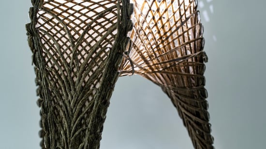
The TFP preform, embroidered on a cotton substrate, predictably bends in the desired zones with similar bending radii for each leg. The seat and legs of the realized stool offered sufficient structural stiffness and aesthetic richness informed by the fiber pattern design. The CFW syntax in the interior of the stool offered a secondary layer of geometrical and formal complexity to complement the exterior. Collectively, the fiber patterns and ordinary tripod geometrical typology familiarized the unusual material expression. The FlexFlax visually recalls woven structures, such as ratan, but in a new material-informed design expression (
Figure 15).
Although a simplified topological optimization strategy used in this experiment was sufficient for estimating NFRP material quantities and its distribution in the structure, with the aim of reaching desired structural strength, it is clear that further research using this approach and further advanced approaches are needed to investigate and deliver exact data about the weight-to-strength ratio, which can be reached using the FlexFlax fabrication approach. At this step, the prototype still remains a demonstrator of
Materials as a Design Tool philosophy [
14], rather than providing exact data about performance of NFRP structures. Undoubtedly, since the FlexFlax workflow was established in the presented paper, the following steps should focus on including more detailed structural simulation, considering exact fiber paths and optimization of the fiber infusion and winding processes. This would allow for exact control over the fiber-to-resin ratio and, consequently, mechanical properties of the generated NFRP. The above-mentioned improvement would allow for realizing several comparable prototypes and estimating their maximum strength through a compression test.
Nonetheless, the high performance comes at the cost of a multi-method fabrication system that may become labor-intensive. Automation potentials are currently under study to overcome those potential drawbacks. There are several aspects that could still be refined, particularly with regards to the CFW step of the process. The use of prepreg rovings at this step was not explored during this project, but it is predicted that this method could decrease fabrication complexity and reduce time consumed during the winding process. The curing time could also be further reduced, both by choosing an alternative resin system characterized by a shorter pot life and by curing the components in an autoclave.
Considering all the above-mentioned conditions, it is justified to speculate about possibilities of application of this system at an architectural scale, in both discrete and continuous natural fiber application. Regarding the discretized design, a controlled prefabrication environment could help with material fabrication constraints. The light weight, in conjunction with a small-scale building component, makes it suitable for modular sustainable building constructions. Finally, as a continuous system, this process could enable partial prefabrication with on-site continuous winding realized by mobile robots [
25]. Such an approach would allow for realization of larger building elements with fewer fragile connections between them. These are the avenues of research that will likely produce rich new architectural modes of production for future sustainable building systems.

 and
and 


