Article

Estimation of Rock Load of Multi-Arch Tunnel with Cracks Using Stress Variable Method

1
Department of Geotechnical Engineering, Saman Corporation, Gyeongggi-do 13837, Korea
2
Department of Civil and Environmental Engineering, Hanyang University, 55 Hanyangdaehak-ro, Sangnok-gu, Ansan 15588, Korea
3
Department of Civil Engineering, Kangwon National University, Samcheok 25913, Korea
4
Department of Architectural Engineering, Kangwon National University, Samcheok 25913, Korea
*
Authors to whom correspondence should be addressed.
Appl. Sci. 2020, 10(9), 3285; https://doi.org/10.3390/app10093285
Submission received: 1 April 2020 / Revised: 28 April 2020 / Accepted: 4 May 2020 / Published: 8 May 2020
(This article belongs to the Special Issue Advances on Structural Engineering)

Abstract

:
In multi-arch tunnels, the increased rock load on the concrete lining of the main tunnel and side walls due to the excavation of adjacent tunnels is critical and must be considered in the design stage. Therefore, this study estimates the rock load of a multi-arch tunnel using two-dimensional numerical analysis, considering rock mass classifications, overburden, and construction steps. The rock load is estimated using two criteria: the factor of safety and stress variable. The rock load is underestimated when the factor of safety is applied to rock mass class III. However, the stress variable method reveals a reasonable rock load as overburden increases. Particularly, the rock load is estimated to be equal to the overburden in shallow tunnels and approximately 0.7 times the tunnel width in deep tunnels. Additionally, the crack-induced rock load is computed using back analysis at the excavation completion stage of adjacent tunnels, yielding the relation between the rock load height and the deformation modulus of the rock mass. Therefore, an accurate estimation of the rock load of multi-arch tunnels emphasizes the importance of a more economical and realistic design and must be addressed in the process of performance-based tunnel design.

1. Introduction

In conventional tunneling, the rock load typically acts on sprayed shotcrete and installed rock bolts in the case of single-tunnel excavation. Consequently, concrete lining is typically applied to resist the water pressure in an undrained condition and under earthquake loads. However, in risky conditions such as the deterioration of rock mass and support system before the durable life of the tunnel, concrete lining can be designed to resist the rock load based on on-site judgment and experience. For concrete lining to work mechanically, the rock load must be considered when designing the supporting system after the excavation. The rock load for the support design is usually estimated using Terzaghi’s rock mass classification system and other rock mass classifications such as rock mass rating (RMR) and tunneling quality index systems [1,2,3]. However, these methods do not provide a specific standard or method to estimate the rock load. It is difficult to estimate the rock load because the states of stress and strain and the time-dependent characteristics of the supporting systems vary with the progress of excavation. Thus, no specific method is available for estimating the rock load transferred to the concrete lining [4]. The estimation method for the support design has been frequently used for the design of concrete lining, but this approach is not a requisite one. In the absence of an estimation method for concrete lining, various estimation methods [5,6,7] that can reflect the interaction between the rock and lining, complex construction steps, geometric conditions, and plastic behavior of the rock have been employed. It is necessary to select a criterion to estimate the rock load for concrete lining and then compare it with the numerical analysis results. Such criteria for single tunnels have been developed in a few studies [8,9], but they must be extended to multi-arch tunnels. The concept of development of rock load during the excavation of a multi-arch tunnel is explained below.
A typical characteristic of multi-arch tunnels is that the tunnel width is typically greater than the tunnel height. In contrast to single tunnels, multi-arch tunnels contain combined cross-sections of more than one tunnel, and the excavation of each cross-section involves a sequence of complex steps. For the construction of a three-arch tunnel, the initial support is typically provided in the form of shotcrete and rock bolts. Subsequently, the central tunnel is provided with a concrete lining and side walls. Next, the adjacent left and right tunnels are excavated. The rock load continues to develop uniformly during the excavation of the central tunnel, which is usually stable owing to the resistance induced by the rock mass and supports. The non-uniformly increasing rock load, which is usually not considered in the design stage of concrete lining and side walls, starts to develop on the central tunnel when the adjacent tunnels are excavated. The side walls, which were once a part of the rock mass surrounding the central tunnel prior to being excavated, are exposed eventually when adjacent tunnels are excavated. This can lead to additional risks to the structural stability. Therefore, to reflect the design of the central tunnel, it is important to consider the increase in rock load according to the construction steps involved in the excavation of adjacent tunnels, as illustrated in Figure 1.
This study selects an appropriate criterion for estimating the rock load of multi-arch tunnels through a parametric study using a numerical approach and also estimates the reasonable rock load according to rock mass classification and overburden. An accurate estimation of rock load is expected to provide tunnel engineers with more realistic/scientific insights into the selection of a support system in a more engineered way and to potentially advance the current three-arch tunnel design.

2. Estimation Methods for Rock Load

2.1. Empirical Methods

Terzaghi’s rock mass classification system, i.e., rock load classification, estimates the rock load to be carried by the steel arches installed for tunnel support [10]. A shear failure plane was assumed for calculating the rock load in this method. The influence of geology on the design of tunnel steel supports was discussed, and various rock loads carried by steel sets were estimated based on the descriptive classification of rock mass classes. Terzaghi defined the rock load classification in a tabulated form, where the rock load on the tunnel steel support is a function of tunnel size and rock mass class.
Moreover, the original RMR system was applied to the rock load [11] and was extended by Bieniawski [3,12] for RMR89 using Equation (1). The rock load was defined as the height of the potential unstable zone above the roof line, which tends to decrease eventually.
Rock   load = 100 R M R 89 100 γ B
The rock load on the pillar in a multi-arch tunnel in Japan was estimated using the relation between the overburden (H) and the combined span (Da) of the multi-arch tunnel [13,14]. As illustrated in Figure 2, the rock load was estimated to be equal to H for shallow tunnels when H was less than or equal to Da and was estimated to be equal to Da when H was greater than Da, as presented in Equations (2) and (3), respectively. However, these empirical equations do not consider the rock conditions and the construction stages of the multi-arch tunnels.
Rock   load   ( m ) = H ,   ( H D a )
Rock   load   ( m ) = D a ,   ( H > D a )

2.2. Numerical Analysis Approach

Various results can be obtained through tunnel stability analysis, such as the displacements in the tunnel periphery, stress and strain distributions surrounding the rock mass, and member forces and moments in the support. It is necessary to consider some criteria to assess the rock load in comparison with the result contours. Two representative criteria for this purpose are described in the following sections.

2.2.1. Criterion of Strength/Stress Ratio

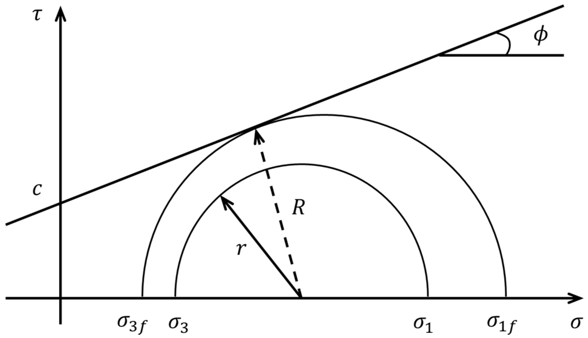
As illustrated in Figure 3, the stress in the Mohr circle can be expressed by plotting shear and normal stresses— τ   and   σ , respectively. At the point where the Mohr circle reaches the Mohr–Coulomb failure envelope, its radius, “R,” can be expressed as, σ 1 f σ 3 f 2 and the current shear stress “r” can be expressed as σ 1 σ 3 2 as shown in Figure 3. The factor of safety can be defined as the strength to stress ratio, as presented in Equation (4). The suggested values of the factor of safety for estimating the rock load owing to excavation are 2.0 and 3.0 [8]. Hence, the value of 3.0 was used as the factor of safety in this study.
F . S . = R r = σ 1 , f σ 3 , f σ 1 σ 3
where σ 1 , f = major principle stress at failure, σ 3 , f = minor principle stress at failure, σ 1 = major principle stress, and σ 3 = minor principle stress.

2.2.2. Criterion of Stress Variable

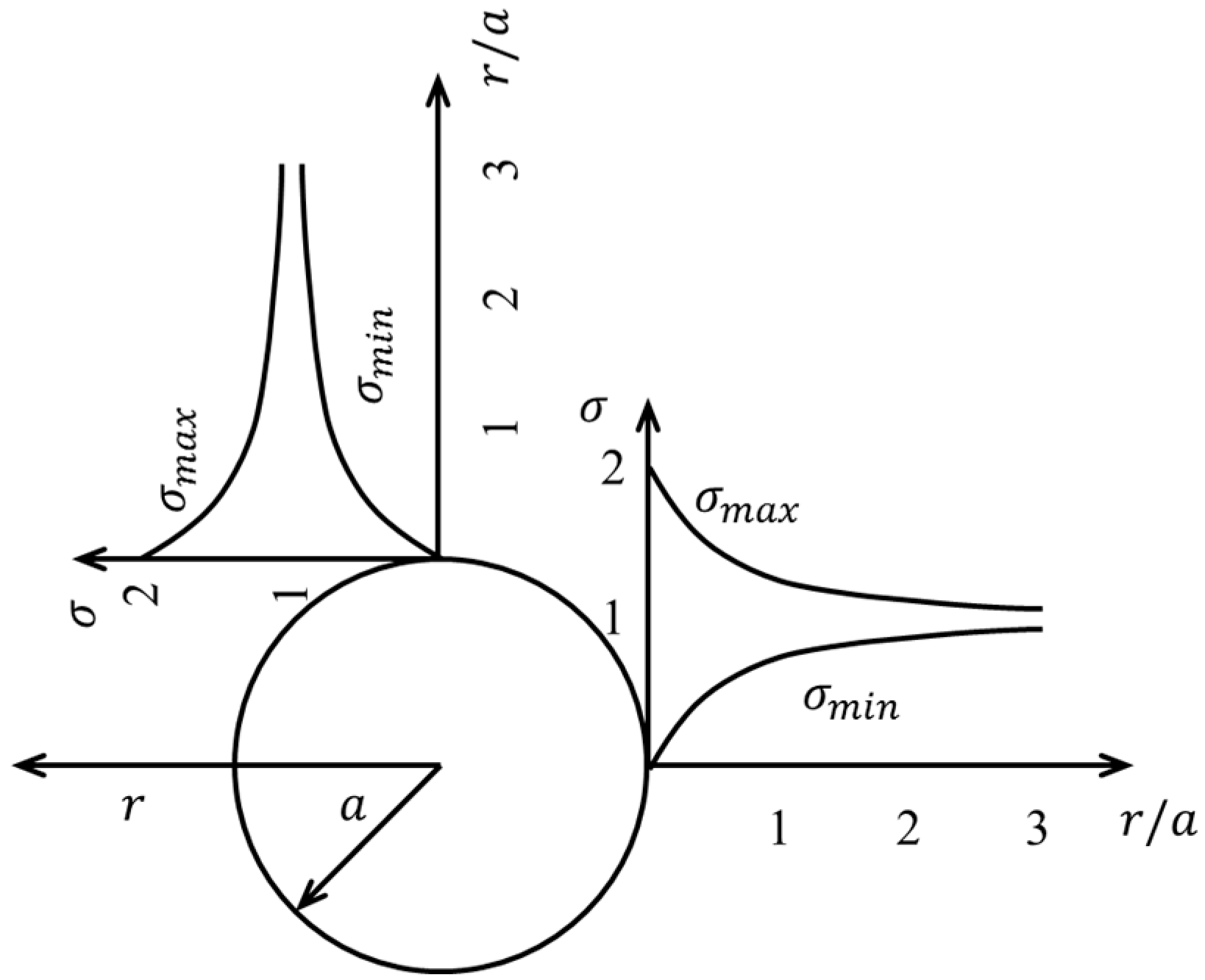
Owing to the stress transfer effect around the tunnel, the minimum principal stress was observed to be zero on the excavation periphery, and it gradually increased as the distance from the excavation periphery increased. In contrast, the maximum principal stress was at its peak near the excavation periphery, and it gradually decreased as the distance from the excavation periphery increased, as illustrated in Figure 4.
The stress variable [9] is defined in Equation (5) as the ratio of the difference between the maximum and minimum principal stresses to the maximum principal stress:
Stress   variable   ( % ) = σ max σ min σ max × 100
where σ max = maximum principal stress and σ min = minimum principal stress.
The rock load on the tunnel is defined as the area around the tunnel periphery, which starts from the peak principal stress and ends at the point where a stress variable of 10% is achieved [9,15]. Based on the available literature, a stress variable of 10% was applied in this study.

3. Numerical Parametric Study of Three-Arch Tunnel Excavation for Rock Load Estimation

3.1. Three-Arch Tunnel for the Analysis

A three-arch station tunnel, as illustrated in Figure 5, having a width of 32.5 m, height of 11.56 m, and length of 165 m, was used to perform a parametric study. The overburden was 40 m high. The center tunnel was excavated and supported with shotcrete, rock bolts, and concrete lining. Note that the concrete lining was installed after the displacement inside the tunnel was converged. Subsequently, the left and right tunnels were constructed.

3.2. Numerical Modeling for Three-Arch Tunnel

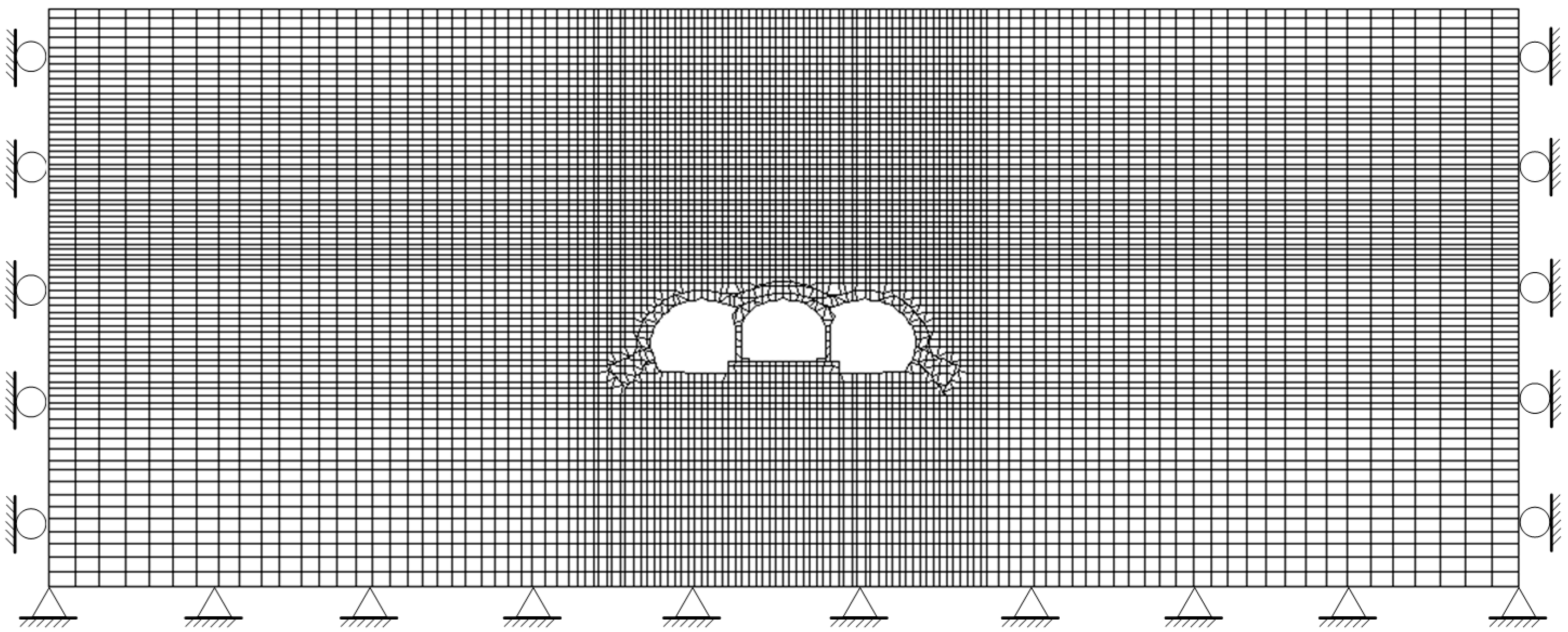
Through numerical simulations, the rock load was estimated from various overburden heights and compared with the empirically calculated load. Two-dimensional numerical analyses in plane-strain conditions were conducted to analyze the development of rock load according to rock mass classification, overburden, and excavation sequence. The commercial finite-difference software, FLAC (version 7.0), was utilized with an explicit solution method. Note that the tunnel was sufficiently long to ignore the strain in the longitudinal direction. A single homogeneous rock mass was applied to the surrounding rock to investigate the difference in rock load according to the rock conditions and overburden. Figure 6 presents the mesh and boundary conditions for the analysis. The boundary condition at the bottom was fixed in the x and y directions, and both sides were fixed only in the x direction. A sufficient distance from the tunnel to the end of the model was used to eliminate the boundary effect.
Table 1 presents the mechanical properties of each rock mass class that were obtained from field investigations and laboratory tests [16]. The rock mass was modeled as an isotropic linear elastic material with the Mohr–Coulomb failure criterion to describe the plastic behavior. In the plastic behavior, associated flow rule was employed. Note that no external load was applied and only gravity force was continuously imposed during the whole simulation process.
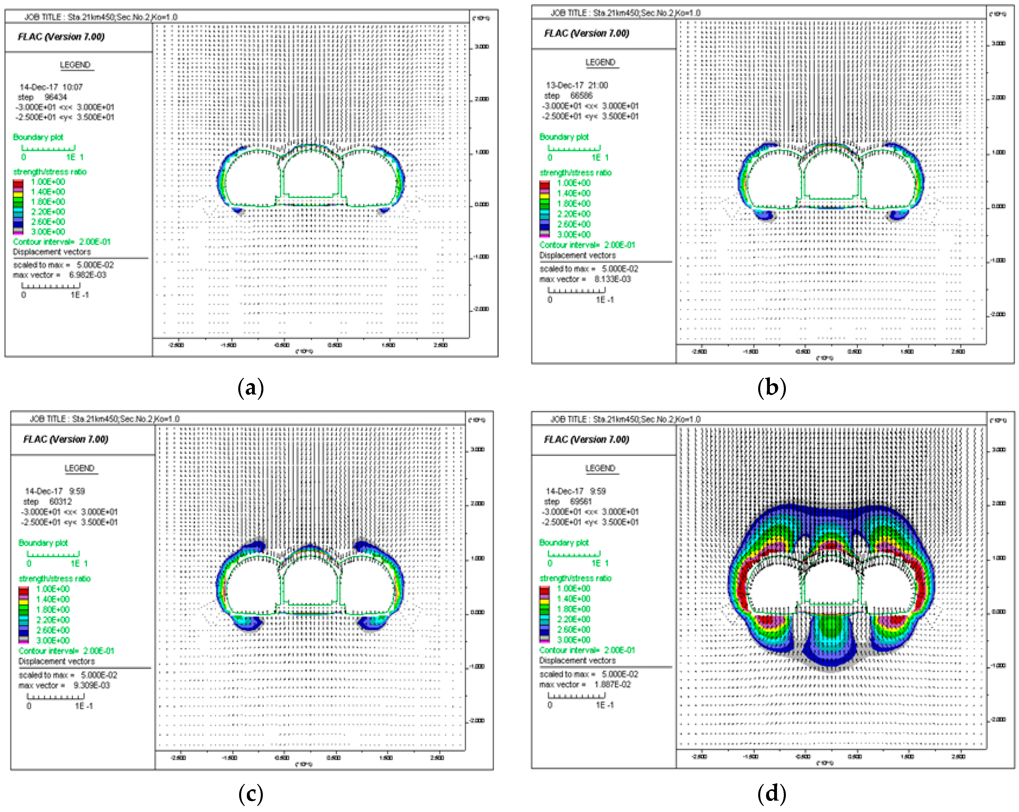
Figure 7 presents a schematic of the parameters considered in this study, where the rock load, overburden, and tunnel width are represented by h, H, and D, respectively. A total of 21 cases of numerical simulations were conducted, involving three rock mass classes with seven overburdens ranging from 10 to 70 m. The rock load was estimated based on a factor of safety of 3.0 [8] and a stress variable of 10% [9], as suggested in previous literature.
The numerical simulation process contains 19 construction steps, as presented in Table 2. All the tunnels in the multi-arch tunnel were excavated using the partial face excavation method, starting with the excavation of the central tunnel, followed by the excavations of the left and right tunnels. The concrete lining was applied only to the central tunnel in the simulation. The shotcrete being used as the tunnel support was simulated in two stages—soft shotcrete (approximately three-hour strength) and hard shotcrete (one-day strength)—depending on its hardening with respect to time. The shotcrete was modeled as a beam element behaving in an elastic manner. To consider the three-dimensional effect in a two-dimensional simulation of tunnel excavation, the load distribution ratio was used as 45%, 35%, and 20% for the three consecutive stages: excavation, soft shotcrete, and hard shotcrete, respectively. As the compressive strength of the shotcrete increased with time, two different elastic moduli were adopted, as presented in Table 3, where the elastic moduli of the soft and hard shotcretes were three-hour and one-day compressive strengths, respectively.

3.3. Estimation of Rock Load According to Overburden in Different Rock Mass Classes

The simulation results of the rock load were obtained in the form of the factor of safety presented as contours for different overburdens in rock mass class III, as illustrated in Figure 8. The result contours presented herein for all the cases were obtained in step 19 for the estimation of the rock load. The contours were obtained for sequential excavation, considering the factor of safety to be greater than 1.0 with an increase in interval of 0.2. It was observed that the factor of safety increased as the distance from the tunnel periphery increased. The rock load was estimated by setting the criterion of the maximum factor of safety as 3.0 during the numerical simulations. The rock load around the tunnel periphery was less than 1 m until an overburden of 60 m, which is considerably less than the failure criterion. However, for an overburden of 70 m, the rock load increased significantly up to a value of 10.5 m, and the stresses acting on the rock mass, even at a considerable distance from the tunnel periphery, were observed to nearly satisfy the Mohr–Coulomb failure criterion.
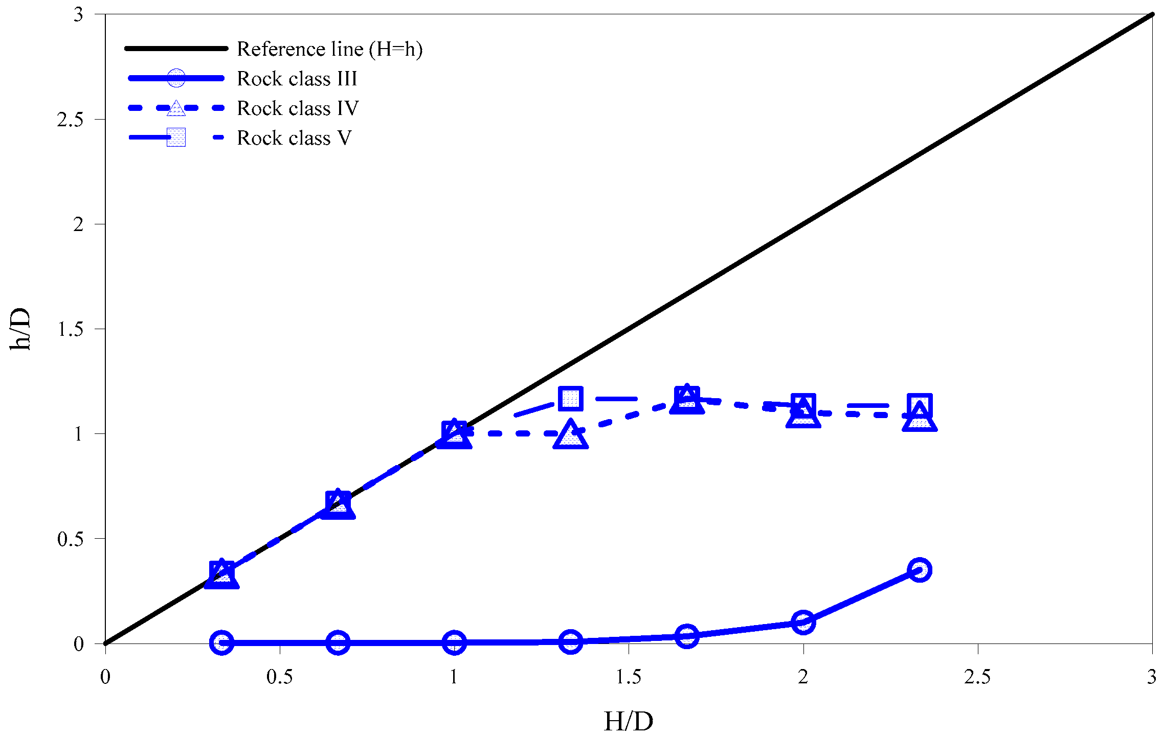
Based on the numerical simulation results, the relation between H/D and h/D was established according to the factor of safety for rock mass classes III, IV, and V, as illustrated in Figure 9. When the estimated rock load, h, is equal to overburden H, the values of H/D and h/D must be equal, as depicted in a linear line in Figure 9 that can be used as a reference line. It was observed that the relation between H/D and h/D for rock mass class III did not follow the reference line, in contrast to the other two rock mass classes. h/D was close to zero even though H/D increased. This indicates that the rock load (h) did not develop, despite the increase in overburden (H), because of the integrity of rock mass class III. However, for both rock mass classes IV and V, h/D followed the reference line up to an H/D of 1.0 and then started converging. This indicates that the rock load (h) developed proportionally with the increase in overburden (H). Therefore, the results demonstrate that the relation between the rock load (h) and the overburden (H) is strongly related to the rock mass class.
Figure 10 presents the contours of the rock load in terms of the stress variable for different overburdens in rock mass class III. Starting from a stress variable of 0%, the contours were obtained for simultaneous excavation with an increase in intervals of 2%. The stress variable was observed to decrease with the decrease in the distance from the tunnel periphery. The rock load was estimated by setting the criterion of the minimum stress variable to be 10% during the simulations. When the overburden was less than 40 m, the rock load was equal to the overburden. When the overburden was greater than 40 m, a smaller rock load was computed, compared to the overburden.
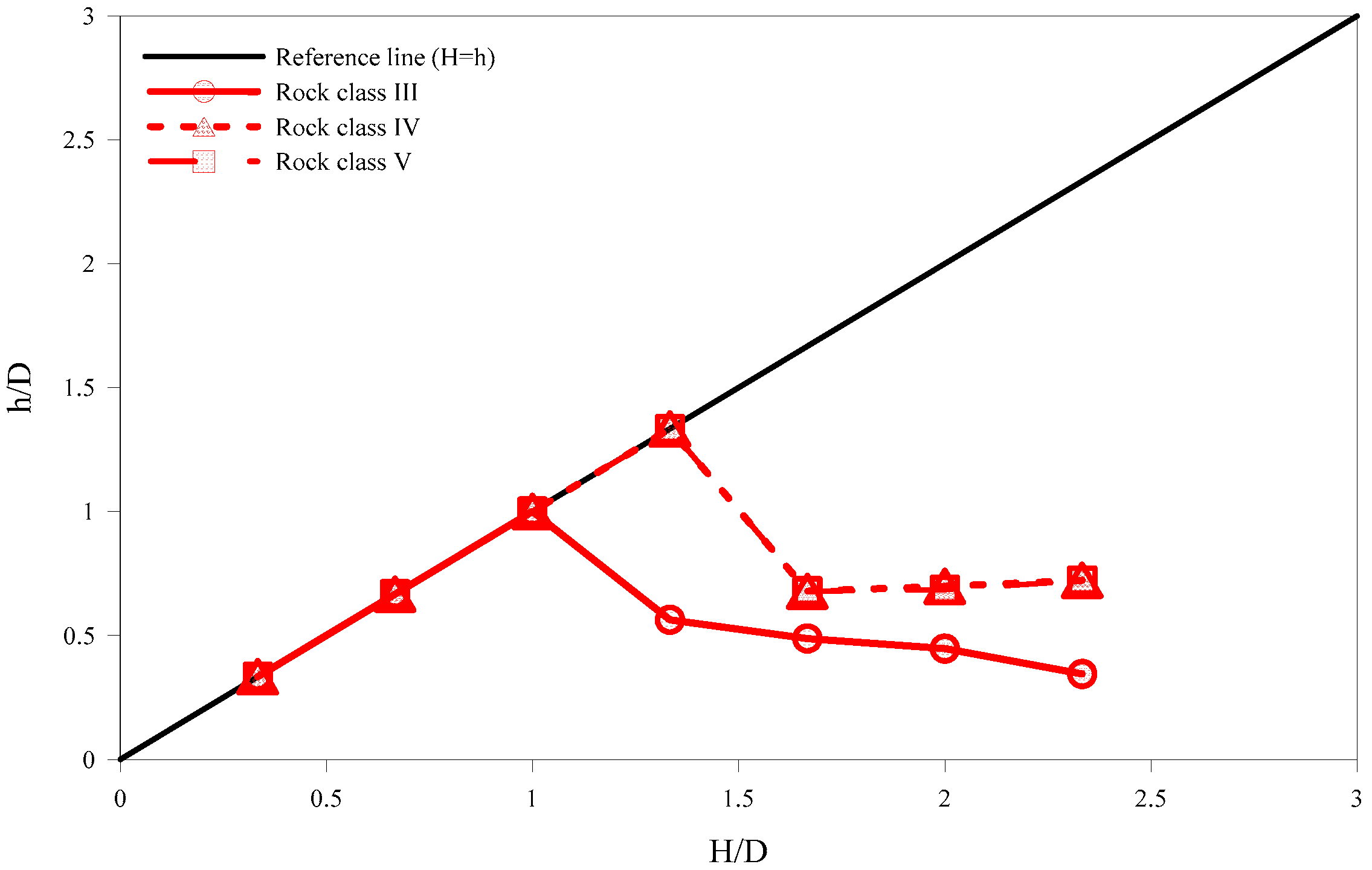
Similarly, the relation between H/D and h/D was investigated with regard to the stress variable for the different rock mass classes (i.e., classes III, IV, and V), as shown in Figure 11. Unlike the previous analysis, the rock load was equal to the overburden for all the rock mass classes, which followed the reference line up to an H/D of 1.0, even though their relation followed the reference line up to 1.5 for both rock mass classes IV and V. After reaching the reference values of 1.0 and 1.5, h/D dropped slightly and converged as H/D increased.
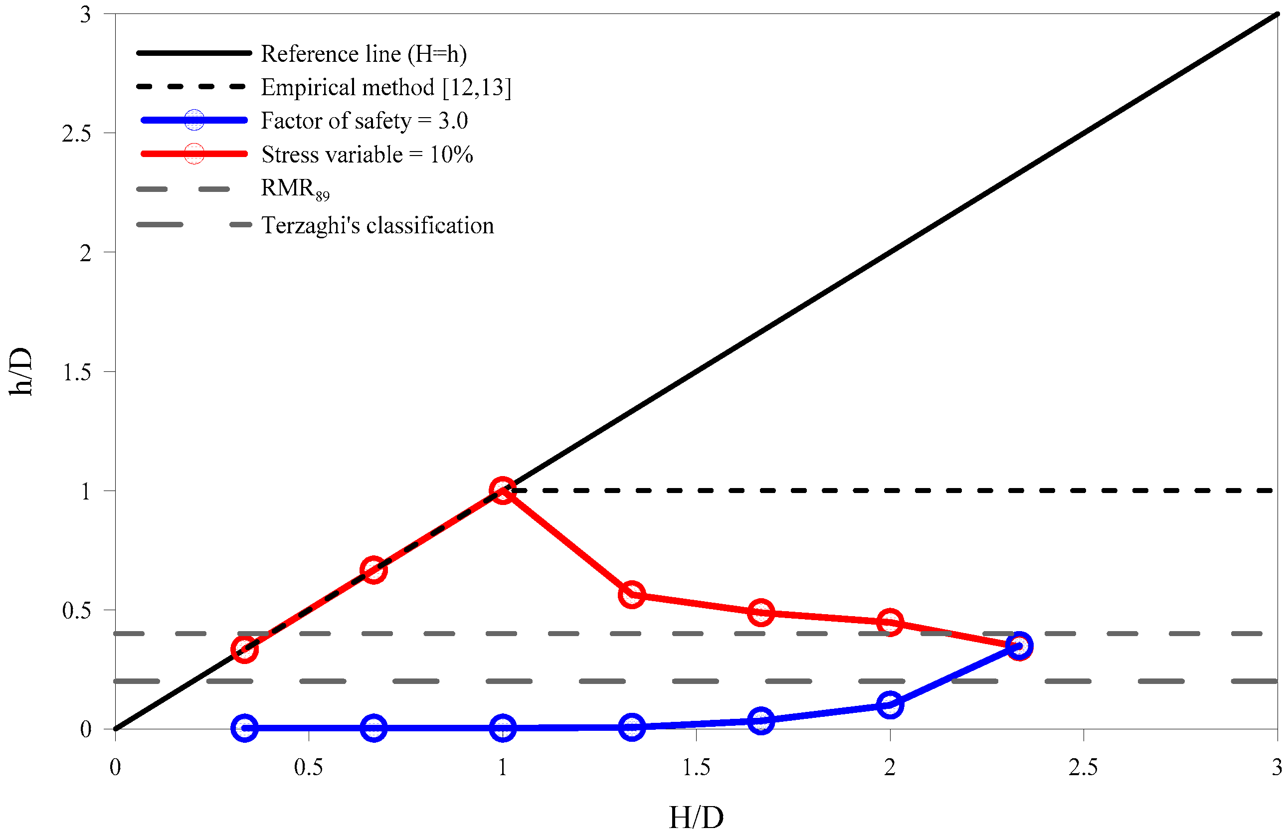
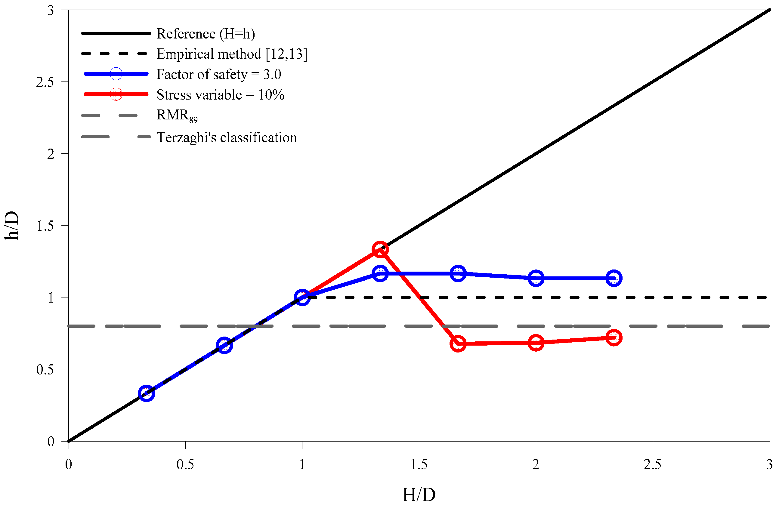
Figure 12 presents the comparison of rock loads estimated from different methods such as the factor of safety, stress variable, empirical method [13,14], RMR89, and Terzaghi’s rock load classification in terms of the relations between H/D and h/D for rock mass class III. As the overburden cannot be considered for RMR89 and Terzaghi’s classification, the constant values of h/D for rock mass class III considering RMR89 and Terzaghi’s classification were 0.4 and 0.2, respectively. For the factor of safety, the maximum value of h/D was obtained as 0.3, even when the value of H/D was as high as 2.3. However, for the stress variable, the rock load was computed to be equal to the overburden until H/D was equal to 1.0. When H/D was greater than 1.0, the h/D value slightly decreased and converged at approximately 0.4. In addition, when H/D was greater than 1.0, the h/D value for the empirical method was computed to be the greatest among all the methods.
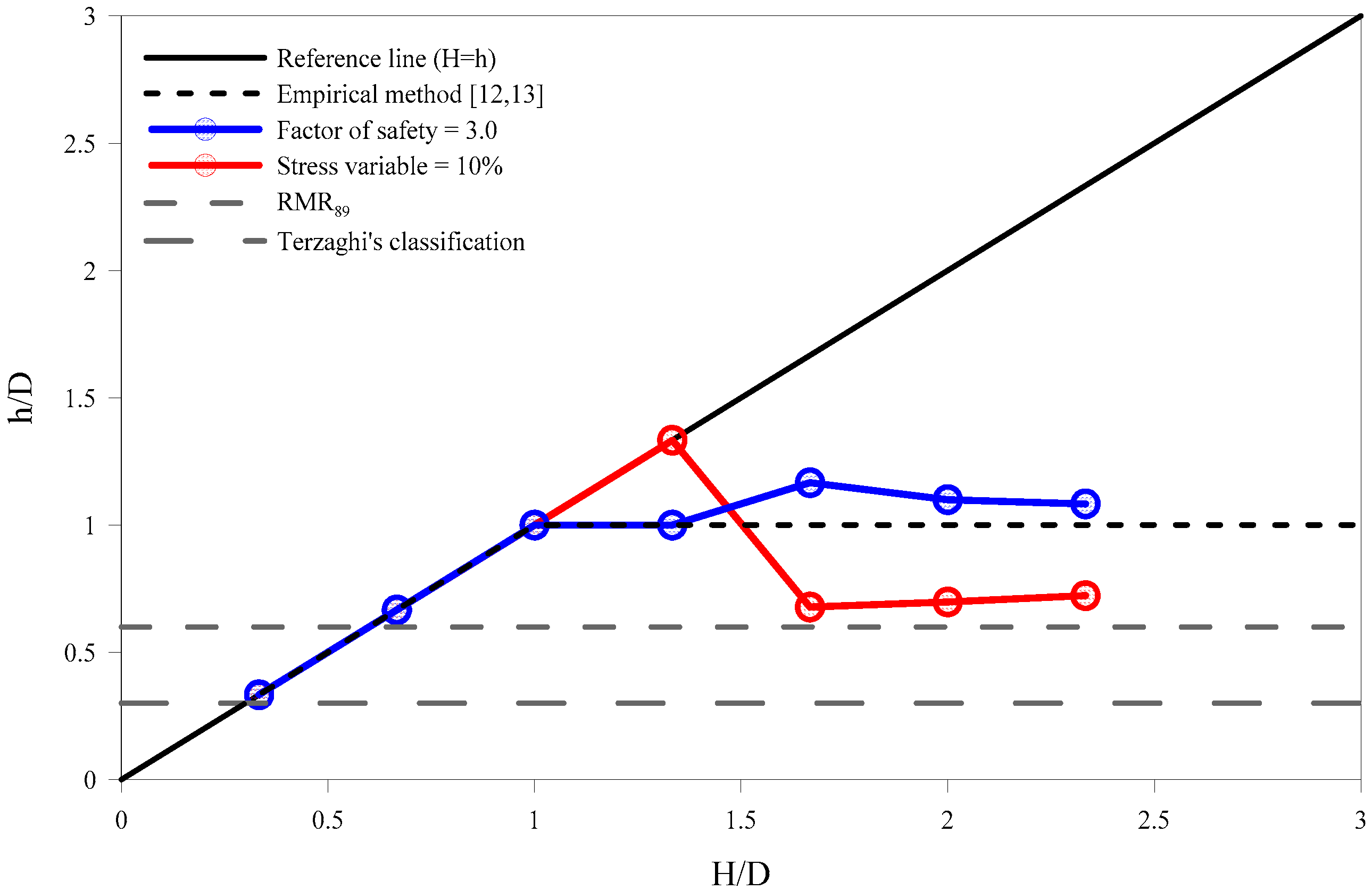
Figure 13 represents the relations between H/D and h/D for rock mass class IV. The constant values of h/D for rock mass class IV, considering RMR89 and Terzaghi’s classification, were 0.6 and 0.3, respectively. For the factor of safety, the rock load was estimated to be equal to the overburden until the value of H/D was up to 1.0. When H/D was greater than 1.0, the h/D value slightly increased and converged at approximately 1.0, which is close to the result of the empirical method. For the stress variable, the rock load was estimated to be equal until the overburden was up to 1.3. Beyond the H/D value of 1.3, the value of h/D fell to 0.6 and converged to the RMR89 line.
Figure 14 represents the relations between H/D and h/D for rock mass class V. The constant values of h/D for rock mass class V, considering both RMR89 and Terzaghi’s classification, were 0.8. As shown in the figure, for both the factor of safety and stress variable methods, the displayed results were similar to those of rock mass class IV. The factor of safety method converged at the value of the empirical method and the stress variable method converged at the value of both RMR89 and Terzaghi’s classification.
The results demonstrate that the empirical and factor of safety methods had a certain drawback in computing the rock load induced by the overburden. In the empirical method, the rock load was constant, regardless of the overburden. The rock load did not develop for rock mass class III, even though the overburden increased in the factor of safety method, resulting in an underestimated design. In contrast, the rock load was computed reasonably in the stress variable approach as the overburden increased.
Hence, from the numerical simulation results, it is deduced that the results obtained from the stress variable method are the most suitable among all the methods. The stress variable exclusively emphasizes that, when the overburden is less than the tunnel width (H < D), the rock load must be considered equal to the overburden value, even for rock mass class III. When the overburden is greater than the tunnel width (H > D) (in deep tunnels, for instance), the rock load relatively starts decreasing with an increase in the overburden value because the arching effect occurs in this case. The results obtained in this study are consistent with those of a previous study by Zhu [17], whereas those obtained using the empirical method potentially overestimate the rock load in most of the cases, except in poor rock conditions.

3.4. Analysis of Rock Load Characteristics with Respect to Construction Steps

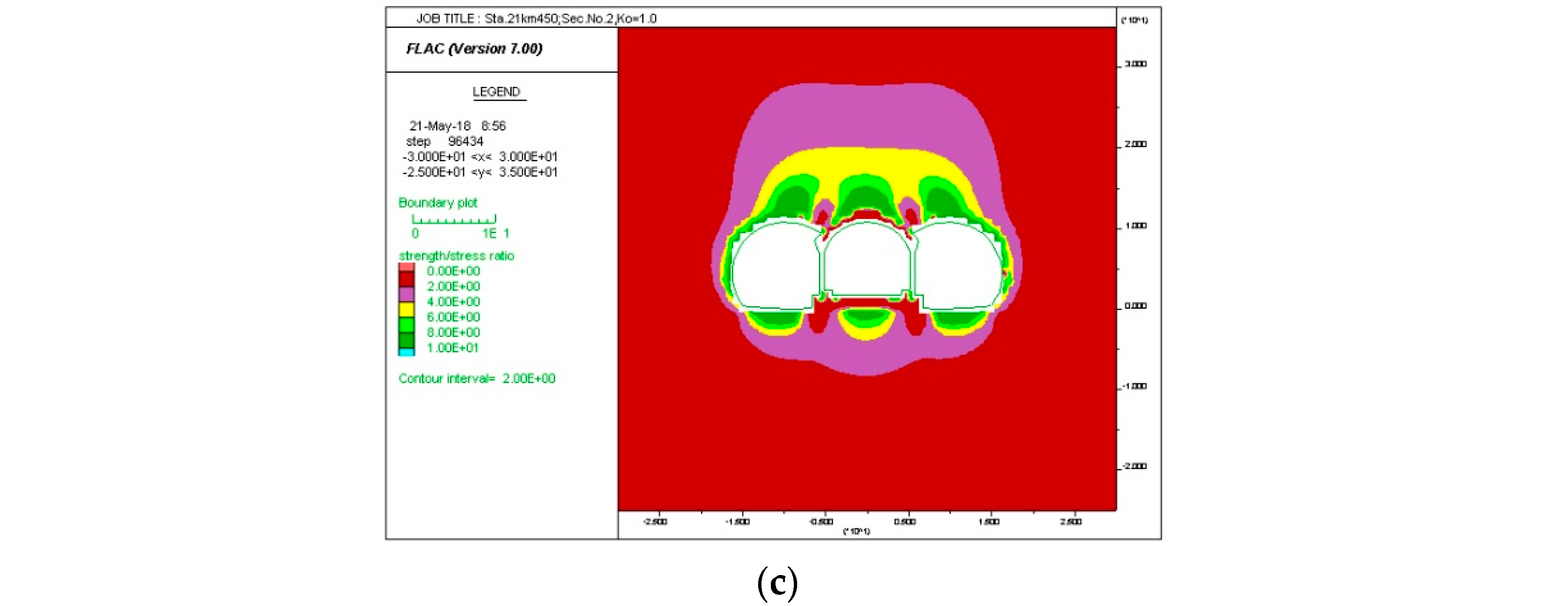
Unlike a single tunnel, a multi-arch tunnel has a larger width than height and requires more construction steps. For a multi-arch tunnel, the concrete lining is constructed after the excavation of the central tunnel, and then, the construction of adjacent tunnels (left and right, as shown in Figure 15) begins. This results in complex construction sequences and stress superposition from the excavation of the adjacent tunnels. Therefore, in this study, the rock load is estimated in every case according to the construction steps involved in the excavation process.
Based on a stress variable of 10%, the increasing trend in the estimated rock load (obtained using the contours) according to the construction steps is analyzed by considering the overburden value to be 40 m for different rock mass classifications. Figure 15 presents the rock load with respect to the construction steps for rock mass class III. As shown in Figure 15a, a small rock load developed after the excavation of the central tunnel was completed in step 6. However, a large amount of rock load developed after the completion of excavations of both the left and right tunnels, as shown in Figure 15b,c, respectively.
The rock load values obtained for different rock classifications with respect to the construction steps are summarized in Table 4. The numerical simulation results show that the rock load had developed considerably when the final tunnel was excavated, especially in poor rock conditions. In this study, the rock load distribution was defined as the ratio of the developed rock load in the final step to the developed rock load in each construction step. In step 6, even though the values of rock load estimated for rock mass classes IV and V were greater than those for rock mass class III, the load distribution for rock mass class III (29.5%) was observed to be greater than that for rock mass classes IV (25.1%) and V (24.6%), as shown in Figure 16.
A similar pattern was observed in step 13. However, the difference between the load distribution for rock mass class III and that for rock mass classes IV and V was observed to be greater than the difference in step 6. In rock mass class III, the magnitude of rock load observed to be developed in each step was approximately equal. However, in rock mass classes IV and V, approximately 60% of the rock load was observed to develop between steps 13 and 19. The study results show that the load distribution is relatively greater when the central tunnel is excavated in good rock conditions as compared with the excavation in poorer rock conditions. This observed phenomenon is similar to the concept of the ground reaction curve, where the better the rock conditions for the excavation process, the lesser the displacement observed, and the earlier the occurrence of stress relaxation.
The analyses results indicate that the rock load does not develop to a considerable level in rock mass class III. However, in rock mass classes IV and V, the rock load develops to a large extent with each construction step. Therefore, for all the rock conditions below rock mass class IV, the overall stability of the tunnel during the excavation of the left and right tunnels must be emphasized more than that during the excavation of the central tunnel, to perform the stability analysis.

4. Crack Analysis by Stress Transition Effect

As mentioned in the previous section, for a three-arch tunnel, the adjacent tunnels on both sides of the central tunnel are excavated after ensuring that the displacement converges. However, the excavation of an adjacent tunnel induced an increase in the rock load and the stress transfer to the corners, resulting in cracks at the corners of the concrete lining, where the stress concentration may occur. Therefore, structural analyses were conducted on the concrete lining of the central tunnel using the beam-spring model. The crack-induced rock load was back-calculated by applying the rock load to the corner of the lining.
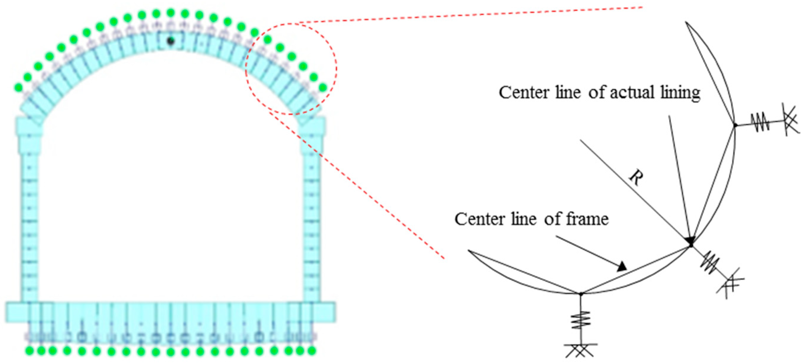
As presented in Figure 17, the concrete lining is modeled as beam and springs attached in the radial direction to the beam, to consider the interaction between the concrete lining and the surrounding ground. Note that the springs were only attached to the crown and inverted, and both sides were free boundary conditions.
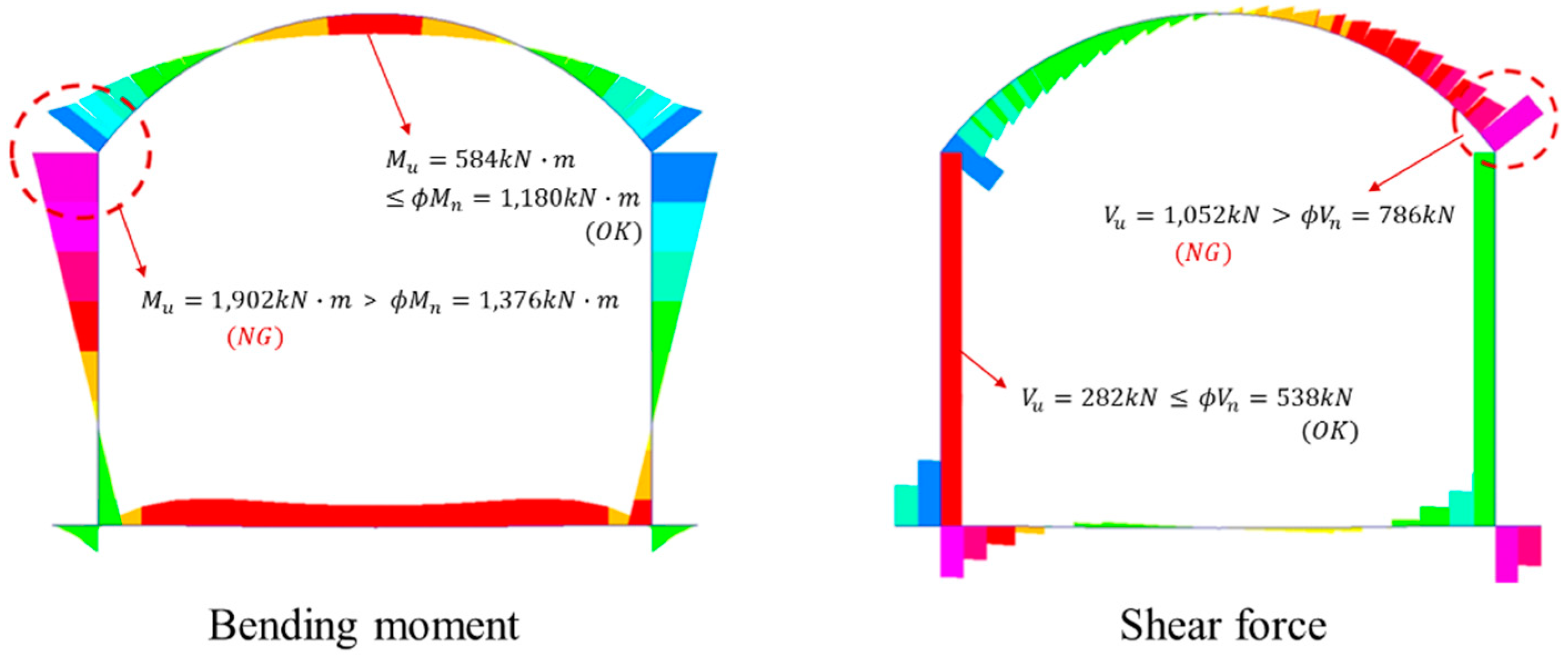
The concrete lining was modeled as beam elements with an elastic modulus of 27.6 GPa and a thickness of 600 mm. The excavation of the left tunnel may impose the rock load on the central tunnel, resulting in shear forces and bending moment at the shoulder where the stresses were concentrated, as shown in Figure 18. Through back analysis, the rock load of the central tunnel was computed as 209 kN/m2, resulting in a rock load height of 10 m. This indicated that the cracks occurred at both shoulders of the central tunnel when the adjacent tunnels were excavated under the rock load height of more than 10 m.
These results indicate whether the rock load causes the cracks on the central tunnel during the excavation of adjacent tunnels. Figure 19 presents the rock load heights at various deformation moduli of the rock at the stage of completion of excavation of the left tunnel. As shown in the figure, a rock load height of 18.5 m was computed after the excavation of the left tunnel. This height is greater than the crack-induced rock load height of 10 m. In addition, when the modulus of rock was less than 4000 MPa, the rock load height was computed as more than 10 m.

5. Conclusions

The following conclusions are obtained from this study:
  • A multi-arch tunnel consists of multiple tunnels connected parallel to each other, and it has a structurally weak shape because the tunnel width is typically greater than the tunnel height. After the excavation and provision of concrete lining in the initial tunnel, the adjacent tunnels are excavated and connected to the pre-excavated tunnel. The displacement and stress distribution in the periphery of the pre-excavated tunnel are affected by the excavation of the adjacent tunnels until the complete cross-section of the multi-arch tunnel is excavated. Therefore, the rock load developed owing to the excavation of the adjacent tunnels must be considered in designing the concrete lining for the pre-existing tunnel.
  • Although many empirical methods have been developed to investigate the rock load for single tunnels, some limitations remain regarding complex construction steps and the consideration of additional rock load for multi-arch tunnels. Therefore, a numerical analysis approach based on the result contours can be more efficient than the empirical method owing to its capability of considering these limitations.
  • The excavation of the three-arch tunnel was numerically simulated in this study according to the overburden values of 10–70 m in rock mass classes III, IV, and V. Considering the stress variable as 10% for all the rock mass classes, the rock load was estimated to be equal to the overburden when the overburden value was less than 1.0 D. However, when the overburden value was greater than 1.0 D, the rock load was estimated to be approximately 0.7 D, owing to the development of the arching effect, which was less than the empirical result (rock load calculated to be 1.0 D) obtained in the same conditions without considering the rock classification. Based on the estimation of rock load via numerical simulation, it is possible to develop a relatively economical design of the concrete lining in deep tunnels.
  • In the case of poor rock mass conditions, the estimated rock load in multi-arch tunnels varies largely with the construction steps. In rock conditions below rock mass class IV, approximately 60% of the rock load is developed in multi-arch tunnels when the last adjacent tunnel is excavated. Therefore, the design and stability analysis must be performed according to the construction steps while considering the varying rock loads under different rock conditions.
  • Cracks can occur at the shoulders of the central tunnel when the excavation of the adjacent tunnels is completed, resulting in an increase in the rock load and stress concentration. Through the back analysis, the crack-induced rock load should be computed with the corresponding deformation moduli of the rock mass. Therefore, the relation between the rock load height and the deformation moduli of the rock mass can provide better insights into the behavior of a three-arch tunnel.

Author Contributions

H.Y., J.K.L. and H.B. supervised the overall study and designed the scheme for rock load estimation and performed numerical analyses. H.B. and W.-J.P. analyzed the results and prepared the manuscript. All authors have read and agreed to the published version of the manuscript.

Funding

This work was supported by the National Research Foundation of Korea (NRF) grant funded by the Korea government (No.NRF-2018R1D1A3B07045700 and NRF-2017R1D1A1B03034236).

Conflicts of Interest

The authors declare no conflict of interest.

References

  1. Bieniawski, Z. Engineering classification of jointed rock masses. Civ. Eng. S. Afr. 1973, 15, 333–343. [Google Scholar]
  2. Barton, N.; Lien, R.; Lunde, J. Engineering classification of rock masses for the design of tunnel support. Rock Mech. 1974, 6, 189–236. [Google Scholar] [CrossRef]
  3. Bieniawski, Z.T. Engineering Rock Mass Classifications: A Complete Manual for Engineers and Geologists in Mining, Civil, and Petroleum Engineering; John Wiley & Sons: Hoboken, NJ, USA, 1989. [Google Scholar]
  4. Kim, J.; Kim, J.; Kim, M.; Yoo, H. Prediction of ground load by performing back analysis using composite support model in concrete lining design. KSCE J. Civ. Eng. 2015, 19, 1697–1706. [Google Scholar] [CrossRef]
  5. Kim, J.-J.; Lee, J.-K.; Kim, J.-U.; Yoo, H.-K. Evaluation of rock load based on critical shear strain concept on tunnels. J. Korean Tunn. Undergr. Space Assoc. 2013, 15, 637–652. [Google Scholar] [CrossRef] [Green Version]
  6. Park, K.H.; Shin, Y.W.; Kim, J.J.; Yoo, H.K. A study on the estimation method of rock load applied to concrete lining using back analysis. J. Korean Soc. Civ. Eng. 2013, 33, 1957–1968. [Google Scholar] [CrossRef]
  7. Lee, J.-K.; Kim, J.-J.; Hafeezur, R.; Yoo, H.-K. Evaluation of rock load based on stress transfer effect due to tunnel excavation. J. Korean Tunn. Undergr. Space Assoc. 2017, 19, 999–1012. [Google Scholar]
  8. You, K.-H. A study on the estimation of stress relaxed zone around a tunnel periphery for the design of 2-arch tunnel lining. J. Korean Tunn. Undergr. Space Assoc. 2005, 7, 343–352. [Google Scholar]
  9. Yang, J.; Wang, S.; Wang, Y.; Li, C. Analysis of arching mechanism and evolution characteristics of tunnel pressure arch. Jordan J. Civ. Eng. 2015, 9, 125–132. [Google Scholar]
  10. Terzaghi, K. Rock Defects and Loads on Tunnel Supports; Harvard University: Cambridge, MA, USA, 1946. [Google Scholar]
  11. Unal, E. Development of Design Guidelines and Roof-Control Standards for Coal-Mine Roofs. Ph.D. Thesis, Pennsylvania State University, Ann Arbor, MI, USA, 1983. [Google Scholar]
  12. Rehman, H.; Ali, W.; Naji, A.; Kim, J.-J.; Abdullah, R.; Yoo, H.-K. Review of rock-mass rating and tunneling quality index systems for tunnel design: Development, refinement, application and limitation. Appl. Sci. 2018, 8, 1250. [Google Scholar] [CrossRef] [Green Version]
  13. Sakai, T.; Miyanomae, S.; Kuroki, S.; Morita, K.; Sakurai, T.; Nashimoto, Y. A design method for reinforced center pillars of twin-bored tunnels. Doboku Gakkai Ronbunshu 2004, 2004, 33–42. [Google Scholar] [CrossRef] [Green Version]
  14. Matsuda, T.; Toyosato, E.; Igarishi, M.; Nashimoto, Y.; Sugiyama, K. A design method of a center-drift and center-pillar type twin-bore tunnel. Proc. Tunn. Eng. Japan Soc. Civ. Eng. 1997, 7, 1–6. [Google Scholar]
  15. Wang, S.-R.; Li, C.-L.; Wang, Y.-G.; Zou, Z.-S. Evolution characteristics analysis of pressure-arch in a double-arch tunnel. Teh. Vjesn. 2016, 23, 181–189. [Google Scholar]
  16. Korean Rail Network Authority. Geotechnical Investigation Report for the Construction of Railway of High Speed Railway in Seoul; Korean Rail Network Authority: Daejeon, Korea, 2011. [Google Scholar]
  17. Zhu, Z.; Sun, M.; Chen, M. Calculation of surrounding rock pressure on multi-arch tunnel. Int. Conf. Transp. Eng. 2009, 990–996. [Google Scholar]
Figure 1. Mechanism of rock load development in a multi-arch tunnel.
Applsci 10 03285 g001
Figure 2. Empirical method to estimate rock load acting on the multi-arch tunnel.
Applsci 10 03285 g002
Figure 3. Criteria of strength–stress ratio.
Applsci 10 03285 g003
Figure 4. Schematic of the stress variable concept where “a” is the tunnel radius.
Applsci 10 03285 g004
Figure 5. Three-arch tunnel: (a) air view (b) cross-sectional view.
Applsci 10 03285 g005
Figure 6. Two-dimensional model showing the finite mesh and boundary conditions for the analysis.
Applsci 10 03285 g006
Figure 7. Schematic of the parameters used in this study.
Applsci 10 03285 g007
Figure 8. Estimation of rock load based on the factor of safety = 3.0 in rock mass class III, (a) overburden = 40 m (1.3 D); (b) overburden = 50 m (1.7 D); (c) overburden = 60 m (2.0 D); (d) overburden = 70 m (2.3 D).
Applsci 10 03285 g008
Figure 9. Relation between H/D and h/D from the factor of safety method.
Applsci 10 03285 g009
Figure 10. Estimation of rock load in terms of the stress variable of 10% in rock mass class III, (a) overburden = 40 m (1.3 D); (b) overburden = 50 m (1.7 D); (c) overburden = 60 m (2.0 D); (d) overburden = 70 m (2.3 D).
Applsci 10 03285 g010
Figure 11. Relation between H/D and h/D from the stress variable method.
Applsci 10 03285 g011
Figure 12. Relation between H/D and h/D for rock mass class III considering the factor of safety and stress variable.
Applsci 10 03285 g012
Figure 13. Relation between H/D and h/D for rock mass class IV considering the factor of safety and stress variable.
Applsci 10 03285 g013
Figure 14. Relation between H/D and h/D for rock mass class V considering the factor of safety and stress variable.
Applsci 10 03285 g014
Figure 15. Rock load estimation based on the stress variable of 10% according to the construction steps: (a) excavation of the central tunnel, completed in step 6; (b) excavation of the left tunnel, completed in step 13; (c) excavation of the right tunnel, completed in step 19.
Applsci 10 03285 g015aApplsci 10 03285 g015b
Figure 16. Rock load development during various construction steps.
Applsci 10 03285 g016
Figure 17. Structural analysis of the concrete lining of the central tunnel using the beam-spring model.
Applsci 10 03285 g017
Figure 18. Bending moment and shear force distribution on the concrete lining of the central tunnel.
Applsci 10 03285 g018
Figure 19. Rock load heights at various deformation moduli after the completion of excavation of the left tunnel.
Applsci 10 03285 g019
Table 1. Mechanical material properties of different rock mass classes.
Rock Mass Class.Unit Weight (kN/m3)Cohesion (kPa)Friction Angle (°)Deformation Modulus (MPa)Poisson’s Ratio
III 25.0102038.050000.25
IV23.050035.025000.28
V 21.010033.010000.30
Table 2. Numerical analysis sequences with respect to construction steps and load distribution ratios.
Construction StepsConstruction ConditionLoad Distribution Ratio (%)
1Excavation of top-heading in central tunnel45
2Soft shotcrete at top-heading in central tunnel35
3Hard shotcrete at top-heading in central tunnel20
4Bench excavation in central tunnel45
5Soft shotcrete at bench in central tunnel35
6Hard shotcrete at bench in central tunnel20
7Concrete lining in central tunnel-
8Excavation of top-heading in left tunnel45
9Soft shotcrete at top-heading in left tunnel35
10Hard shotcrete at top-heading in left tunnel20
11Bench excavation in left tunnel45
12Soft shotcrete at bench in left tunnel35
13Hard shotcrete at bench in left tunnel20
14Excavation of top-heading in right tunnel45
15Soft shotcrete at top-heading in right tunnel35
16Hard shotcrete at top-heading in right tunnel20
17Bench excavation in right tunnel45
18Soft shotcrete at bench in right tunnel35
19Hard shotcrete at bench in right tunnel20
Table 3. Material properties of shotcrete used in the simulation.
ShotcreteUnit Weight (kN/m3)Compressive Strength (MPa)Deformation Modulus (MPa)Poisson’s Ratio
Soft shotcrete 241.150000.20
Hard shotcrete241015,0000.20
Table 4. Rock load obtained in different rock classifications with respect to the construction steps.
Rock Mass ClassRock Load Height (m) and Extent of Load Distribution 1 (%)
Step 6Step 13Step 19
III3.8 (29.5%)8.7 (67.4%)12.9 (100%)
IV9.5 (25.1%)15.5 (39.7%)39 (100%)
V9.6 (24.6%)15.7 (40.3%)39 (100%)
1 Ratio of the rock load developed until the step under consideration to the final rock load developed until step 19.