Article

Simulation Analysis and Experimental Verification of the Locking Torque of the Microgravity Platform of the Chinese Space Station

1
State Key Laboratory of Robotics, Shenyang Institute of Automation, Chinese Academy of Sciences, Shenyang 110016, China
2
Institutes for Robotics and Intelligent Manufacturing, Chinese Academy of Sciences, Shenyang 110169, China
*
Author to whom correspondence should be addressed.
Appl. Sci. 2021, 11(1), 102; https://doi.org/10.3390/app11010102
Submission received: 12 November 2020 / Revised: 10 December 2020 / Accepted: 21 December 2020 / Published: 24 December 2020
(This article belongs to the Special Issue Modeling, Design, and Optimization of Flexible Mechanical Systems)

Abstract

:
The Microgravity Platform (MP) of the Chinese Space Station is locked and released by Lock-or-Release (L/R) mechanism on both sides. In order to ensure the safety and reliability of the MP under the vibration environment during the rocket launch, the L/R mechanism must output the appropriate locking torque value. Based on the structural characteristics of the Scientific Experiment Cabinet (SEC), this paper proposes a method of evaluating locking torque by combining theory with experiment, and the relationship between locking force and locking torque of L/R mechanism is proved that the locking force on both sides can reach 2000 N at 25 Nm driving torque. Finally, it is verified by vibration test that the locking torque obtained by this method can effectively guarantee the safety and reliability of the MP under vibration environment.

1. Introduction

As an ideal platform to carry out space science experiments, frontier science and technology exploration, the space station has received great attention at home and abroad [1]. The International Space Station has been in service for many years as the largest space facility and low-earth orbit space laboratory in human history [2]. Many studies have been carried out in the fields of technology development and verification, human research, biology and biotechnology, physical science, earth and space science [3,4]. The establishment of the space laboratory of the Chinese Space Station will enable China to carry out long-term space microgravity experiments and provide guarantee for space science exploration, which has great significance in promoting frontier space science exploration and leading the future development of space application technology. The conceptual model of the Chinese Space Station is shown in Figure 1, which is composed of a core module and two experimental modules, Tianzhou-1 and Shenzhou-11. As the most important part of the space laboratory, many different types of SEC are arranged in the Space Station, which are the carrier to carry out all scientific experiments. According to the overall plan of the application system, the MP are installed inside the Medical Samples and High Microgravity Laboratory Cabinet (MSHML) that is one of many SEC in the core module of the Chinese Space Station, and the hierarchical relation shown in the Figure 1. The MP is used to carry out a variety of scientific experiments in space, including materials science, microgravity fluid, and biotechnology [5,6,7,8,9].
The MP is a cuboid test device located in the middle part of the MSHML, which is fixed by the L/R mechanism during the launch. When it arrives at the predetermined orbit of the space station, the L/R mechanism on both sides is driven in reverse at the same time to release the MP for scientific research [10,11]. For the special locking requirements of the MP, the locking force directly affects the locking reliability of the MP. In the process of launching into orbit, the MSHML will experience a variety of mechanical environments, including vibration, impact, noise, constant acceleration, etc. [12]. When resonance occurs in the MSHML, if the locking torque supplied by the L/R mechanism on both sides is insufficient, relative displacement may occur between the L/R mechanism and the MP, which may cause relative slippage between the thread of the locking device, and even cause incomplete contact between the MP and the lead screws of the L/R mechanism on both sides. The MSHML cannot form symmetrical and regular pretension deformation, and it may cause rich and complex nonlinear vibration phenomena of the platform, such as frequency doubling, frequency division, bifurcation, chaos during the rocket launch [13]. With the continuous action of vibration load, intensive dynamic response will occur, which may lead to the collapse or work performance degradation of the MSHML. It also poses a threat to personnel and rocket, and the damage in orbit is not easy to repair. On the other hand if the locking force is too large, excessive pretension will be generated inside the MSHML, which causes excessive predeformation of the structure, and due to the excessive load, poor lubrication, and other harsh operating conditions, faults may occur in the gear systems of the L/R mechanism [14]. Keeping this state for a long time will also have a significant impact on the cabinet, even permanent deformation. In order to ensure the high reliability and safety of the MP in the rocket launching environment, it is very important to evaluate the reasonable locking torque.
Aiming at this special problem, this paper designs a method to evaluate the locking torque based on the characteristics of the MSHML. Through theoretical analysis, numerical simulation, experiment, and other aspects, the reliability of the L/R mechanism is analyzed to obtain the locking torque that meets the vibration environment.

2. L/R Mechanism Design

During the launch process, the SEC is fixed to the side wall of the space station module through the joints at the top and bottom. The schematic diagram of the MSHML is shown in Figure 2, which is composed of three parts: the main structure of the experiment cabinet, the L/R mechanism, and the MP.
The L/R mechanism is a single-drive multioutput lifting mechanism, which is composed of a driving device, a gear transmission device, and a locking device. It is specifically developed and equipped for the MP and provides a higher level of controlled environment for samples and instruments to facilitate fine operation in different experiments. When the L/R mechanism is locking, coaxial gears Z2 and Z3 are driven by the bevel gear Z1 on the L/R mechanism driving device. Next, Z3 drives the central gear Z4 that drives the four branch gears Z5, Z6, Z7, and Z8 to rotate synchronously so that the four lead screws of the L/R mechanism move forward to tighten the MP. When the end of the lead screw contacts with the groove of the MP, a locking force is generated until the motor reaches a predetermined locking torque, the driving device stops working. At this time, MP is safely locked, and the preload on both sides is F.

3. Principle

A simplified model is used in the analysis of structural dynamics. The MSHML is regarded as the boundary, the MP is equivalent to the concentrated mass, and the system is simplified to a single-degree-of-freedom vibration system. Its response is the forced vibration under the basic excitation [15]. A damped forced vibration mechanical model is adopted to establish the dynamic model as shown in Figure 3.
Preload is applied on the MP, the static equilibrium position is as the origin and the right direction is as positive. The amplitude is B, the vibration frequency is ω , the mass of the MP is m, the displacement excitation changed by time is x f ( t ) , and the vibration rule is expressed as:
x f ( t ) = B e i ω t
The harmonic excitation force can be written as:
m x ¨ f = m B ω 2 e i ω t
The displacement of the MP relative to the cabinet is x 1 , the damping ratio is ζ , and the natural frequency is ω 1 , so the differential equation of motion is shown in Equation (3).
x ¨ 1 + 2 ζ ω 0 x ˙ 1 + ω 0 2 x 1 = B ω 2 e i ω t
The relative motion amplitude is A1, phase is θ 1 and amplitude amplification factor is β 1 = A 1 / B , and Equation (4) can be obtained.
x 1 = β B e i ( ω t θ 1 )
The frequency ratio is s = ω / ω 0 , the relation of the parameters β 1 and θ 1 between the excitation frequency is given below:
β 1 ( s ) = s 2 ( 1 s 2 ) 2 + ( 2 ζ s ) 2
θ 1 ( s ) = arctan ( 2 ζ s 1 s 2 )
The absolute displacement x of the MP is equal to the sum of the relative displacement of x 1 and the displacement of the base x f .
x = β 1 B e i ( ω t θ 1 ) + B e i ω t = ( β 1 + e i θ 1 ) B e i ( ω t θ 1 )
By using Equations (5) and (6), it can be deduced:
β 1 + e i θ 1 = 1 + 2 i ζ s ( 1 s 2 ) 2 + ( 2 ζ s ) 2
Let the absolute amplitude be A, and substitute Equation (9) into Equation (8) to get:
x = A e i ( ω t θ )
where the phase difference q is as below:
θ = arctan ( 2 ζ s 1 s 2 ) arctan ( 2 ζ s )
The simple harmonic inertia force generated by the MP can be written:
F = m x ¨ = m A ω 2 e i ( ω t θ )
The displacement response x in the vibration process can be obtained by differential Equation (9). According to Equation (11), the inertial force F in the vibration process can be solved. The preload on the left side is F1, and the preload on the right side is F2, and in the static state, F1 = F2.
In the first 1/4 period of sinusoidal vibration, the MSHML starts to move to the right side. Due to the influence of inertia, the MP pressure is on the left side of the cabinet, at this time F1 = F2 + F. As the vibration continues, the MP will continue to pressure on the left, so F1 will increase and F2 will decrease. If the preload F2 is too small, the situation of F1 = 0 will occur, and at this time it is in the critical state of contact. Under the action of inertia, the MP will continue to move to the left, pressing the left beam, F2 will continue to increase, and it will cause the separation between the right locking screw and the MP.
When the sinusoidal vibration in the first stage of two quarters to three quarters of a period, displacement starts to move in the opposite direction, producing the opposite acceleration, and F2 decreases gradually. When the locking device on the right side starts to contact with the MP, there will be impact generated, and as pulse signal F1 will increase gradually. Similarly, the effect of F2 = 0 and the impact of the next contact must occur during continuous exercise.
With the reciprocating vibration, the periodic impact response will occur between the MP and the lead screw, which will affect the reliability of the product. In order to avoid the impact in the vibration process, the preload F1 and F2 must be large enough, and the preload should not be 0 in each cycle of the reciprocating vibration, so as to meet the locking requirements of the MP.

4. Analysis

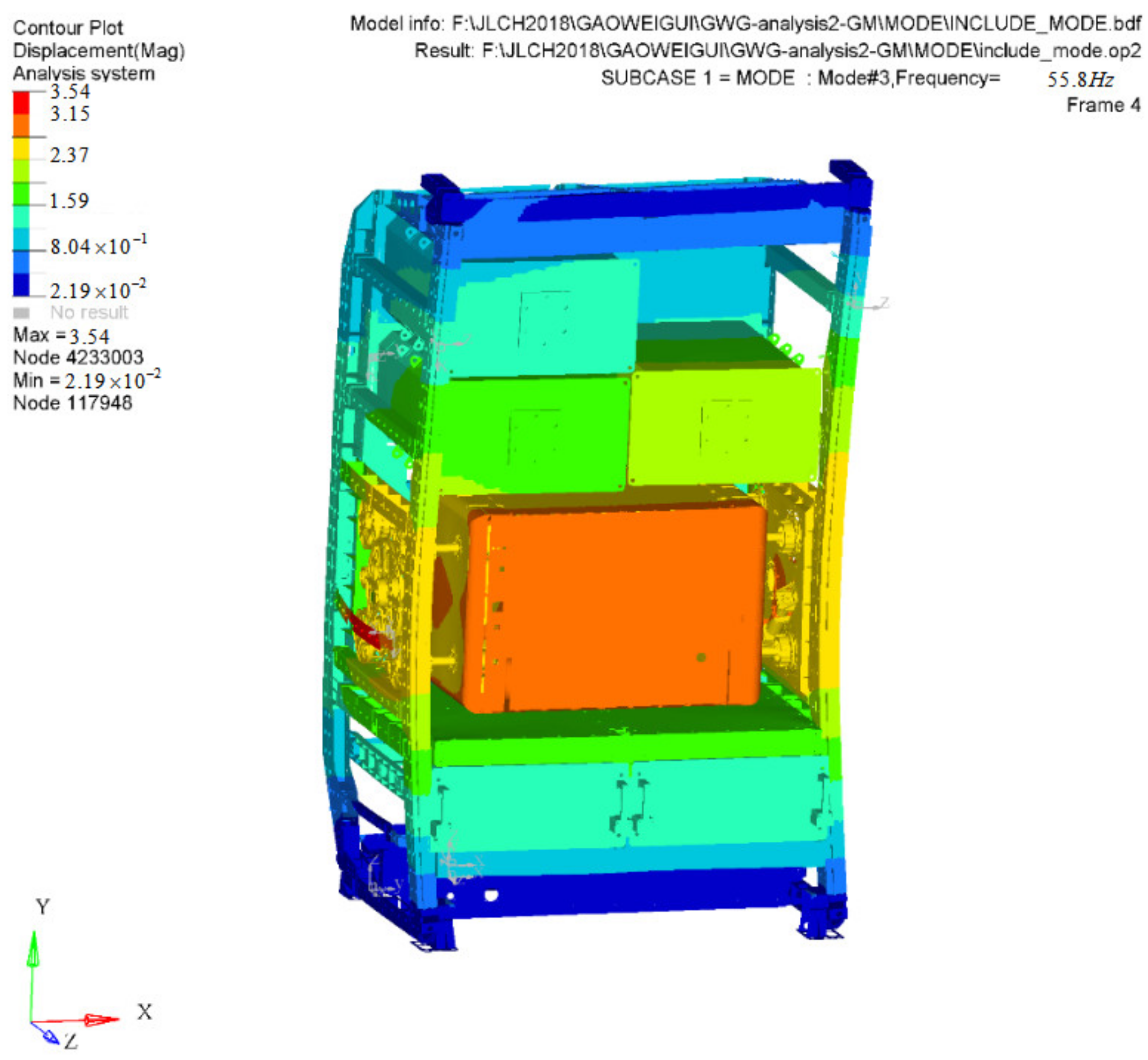
4.1. Frequency Response Analysis

In order to evaluate the proper locking force of the MP under vibration environment, the frequency response analysis of the MSHML was carried out. Dynamic analysis was carried out in the Hypermesh/Patran/Nastran environment: Preprocessing was established in the Hypermesh. The whole model is composed of tetrahedron, hexahedron, shell element, and plate element, with a total of 1,882,080 units and 1,148,797 nodes. 7075 aluminum alloy was mainly used for the main body, and carbon fiber material T300 was used for the skin of the MSHML. The mm-t system of units was used in the analysis and the material parameters are shown in Table 1. The boundary condition was that six degrees of freedom of top and bottom connection points of the MSHML are constrained. The premise of vibration analysis in this analysis is that the MP and the locking screws are not separated, that is, they are locked and reliable, and they are connected by RBE2 as a complete whole to simulate the locking state in the finite element.
Next, the finite element model of the configured MSHML was submitted to Nastran for solution and calculation. The input positions were top and bottom connection points of the MSHML, and the input condition of frequency response analysis is shown in Table 2. Finally, Patran was used for post-processing to extract the MPCFORCES of all nodes on RBE2 connecting to the lead screw at the resonant frequency, and the location of locking force was extracted as shown in Figure 4.
The MPCFORCE of nodes at resonance frequency was extracted, the real and imaginary parts of the proposed node force were summed, respectively, to obtain Fr and Fi, and according to the Pythagorean theorem to obtain the amplitude of locking force, which is the locking force under resonance condition. During the vibration experiment, in order to prevent separating, the preload force of the L/R mechanism must be greater than this value. For safety reasons, it was multiplied by 1.2 that is the safety factor, and the obtained value Fs is the preload force during the vibration experiment.
F S = 1.2 F r 2 + F i 2
Through modal analysis, the x-direction resonance frequency is 55.8 Hz. The cloud diagram of the MSHML in X-direction is shown in Figure 5, and the locking force of eight locking positions at this frequency was extracted as shown in Table 3, and the positions of eight locking force are shown in Figure 6. In the process of locking, the front beam of the MSHML will produce slight predeformation under the action of locking force and absorb part of the energy. The closer it is to the central front beam, the greater the deformation will be. The rear beam is connected to the back structure, with relatively higher structural stiffness and almost no deformation. It can be found from the data in Table 3 that the locking force of the back measuring points is larger than the measuring points in the front. The locking force of the lower measured points is larger than the measured upper points, and the result of the locking force is consistent with the analysis. The maximum locking force is 1606 N at position 8. In order to make the MP lock reliably during vibration, according to Equation (12), the Fs (s = 1, 2, …, 8) can be estimated at no more than 2000 N.

4.2. Static Analysis

The value of the locking force can be obtained through the frequency response analysis of the MSHML. However, the main structure of the MSHML is not a pure rigid body structure. In the process of loading, continuous deformation must occur under the action of locking force. When the stress exceeds the yield limit of the material, structural abnormalities may occur in the main structure of the MSHML, which will affect the functional characteristics, shorten the service life, and even cause structural damage. In order to determine whether the locking force of the frequency response analysis has an impact on the structure or not, the strength and stiffness of the main structure of the MSHML was checked, and the static analysis was carried out. In the static calculation does not consider any damping and other nonlinear factor [16].
In the static analysis, Fs(s = 1, 2, …, 8) was applied on the lead screw of the L/R mechanism, respectively, with the consideration of safety margin. The positions are shown in Figure 6, and the magnitudes of Fs are shown in Table 3. The boundary condition is that six degrees of freedom of top and bottom connection points of the MSHML are constrained. As the rigid unit RBE2 was used to simulate the bolted connection in the simulation process, the surface contact was discretized into node contact.
Figure 7 shows the cloud diagram of the stress response of the MSHML under the load of locking force. It can be seen from the figure that the maximum stress is 230.8 Mpa, which is located at the bolt connection of the beam in the right side. The material here is aeronautical aluminum 7075, and its tensile strength is greater than 500 Mpa, which is far higher than the obtained stress and meets the strength requirements. Therefore, the MSHML will not be damaged when the L/R mechanism is in the process of locking the MP.

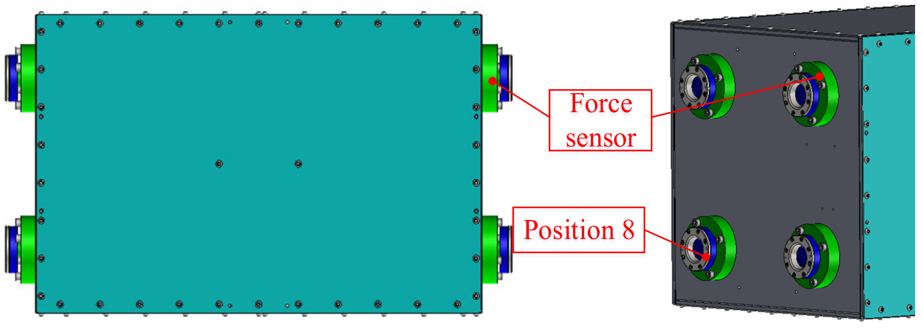
4.3. Locking Force Analysis

In order to measure the locking force more conveniently, pressure sensors were added between the lead screws and the MP. The locations of the sensors are shown in Figure 8. Since these sensors themselves have a certain mass and volume, adding the sensors is equivalent to changing the original structure connection. In order to understand and analyze the transformation of the locking force of the MP during the locking process more clearly, the relationship between the output torque of the motor and the locking force of the MP was obtained, and the consistency of the locking force with and without the sensor was verified under the same torque condition. Adams was used to carry out the rigid–flexible coupling analysis of this process.
The output torque value of the left motor and the locking force at the position 8 shown in Figure 8 were taken as the analysis objects, and the sensor was set as the flexible body to analyze the force relationship between the L/R mechanism and the MP. The comparison diagram of the time history curve of motor torque and locking force under the conditions of sensor addition and no sensor addition was obtained, respectively, as shown in Figure 9 and Figure 10. It can be seen from the figure that the value of the locking force reaches about 2000 N at 180 s, meeting the preset value of the locking force obtained by frequency response analysis. At this time, the motor locking torque is 21.55 Nm. From the Figure 11, the error value of the locking force is within ±1.9% in the two states. It can be judged that it has little influence on the relationship between the locking force and the locking moment whether sensors are added or not. In other words, the numerical value measured by the sensor torque can be used to simulate the situation without the sensor.

5. Experiment

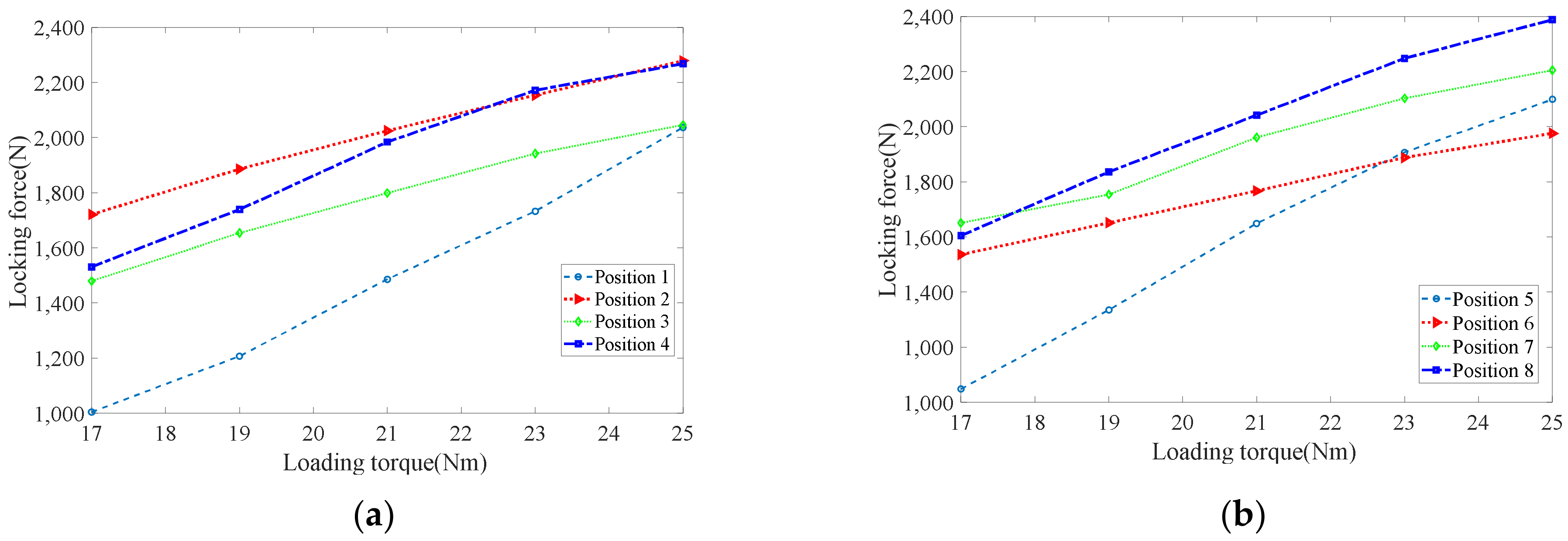
5.1. Locking Force Experiment

On the basis of the above analysis, in order to obtain the real and reliable locking torque value, the locking force of the MP was tested, and the test device is shown in Figure 12. The whole test device includes a data acquisition system, a charge bridge, eight pressure sensors and a computer, in which the force sensor is connected by a quarter bridge.
The torque wrenches were used to tighten the L/R mechanism so as to obtain real-time torque values, and the loading position is as shown in Figure 12. During loading, eight lead screws of the L/R mechanism on both sides were extended to lock the MP at the same time, and eight groups of real-time pressure signals were detected through the pressure sensor. The locations of each sensor are shown in Figure 12. The pressure signals collected by the force sensor were converted by Wheatstone Bridge Circuit [17,18], and then acquired by the data acquisition system, so as to obtain the real-time locking force value. Through data feedback, the relationship between torques and locking forces is shown in Figure 13. When the locking torques reach 25 Nm, the locking forces at the eight locking points exceed 2000 N.

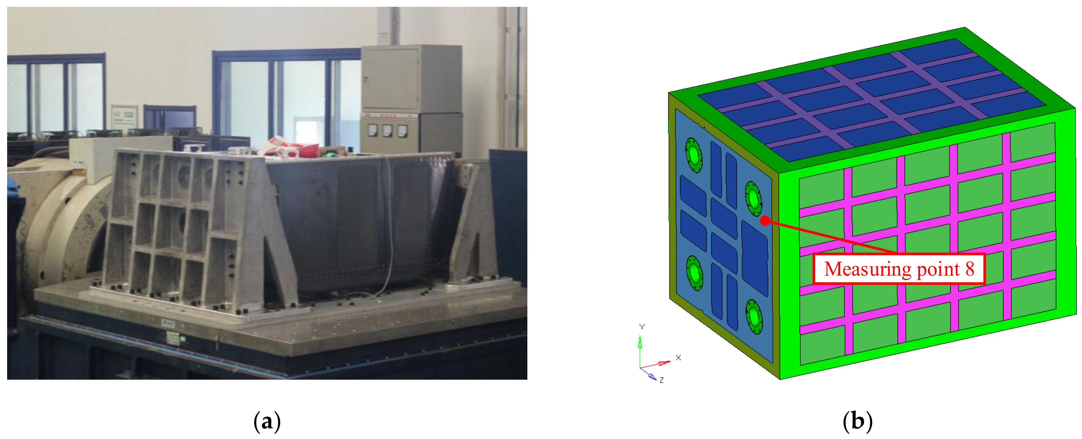
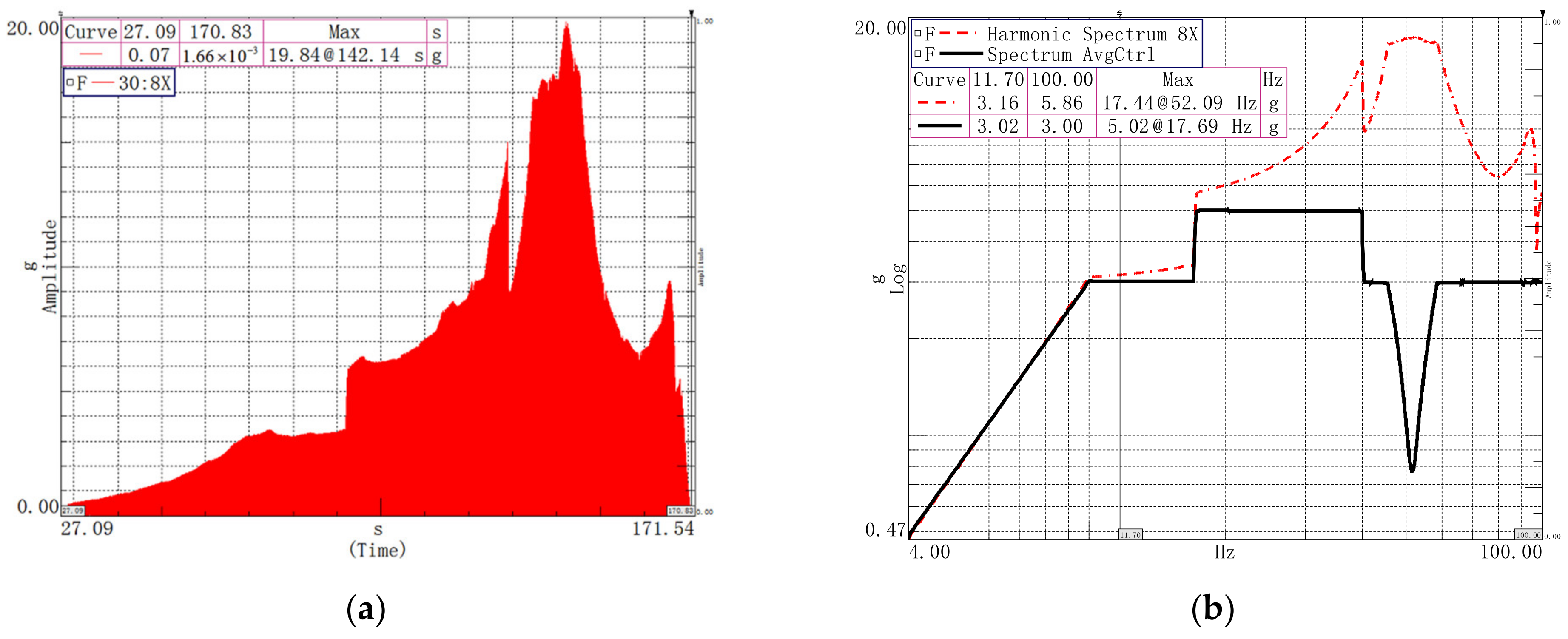
5.2. Vibration Experiment

Vibration experiment plays a very important role in aerospace field [19,20,21]. Sinusoidal vibration excitation can effectively verify the stability of the MP under vibration environment [22]. In order to verify the reliability of the locking force and eliminate faults in the normal life stage, a shake table test was adopted to simulate the mechanical environment of aerospace products and eliminate possible faults on the ground [23,24].
According to the analysis in the previous section, the relationship between locking force and locking torque remains unchanged after the force sensor is added. Therefore, the pressure sensor and its supporting devices are removed, and the L/R mechanism motors reload the MP at the same time until the torque reaches 25 Nm. In this state, sinusoidal vibration test was carried out to verify the reliability of the locking force. The vibration verification test was carried out on the 35-ton vibration platform of Aerospace Hill as shown in Figure 14. There are three times of sinusoidal sweep vibration, and the test sequence is as follows: 0.2 g characteristic sweep, formal sinusoidal sweep, and 0.2 g characteristic sweep. The test conditions of formal sinusoidal sweep were the same as the input of the frequency response analysis described earlier, as shown in Table 1. One acceleration sensor was placed on the MP to detect the acceleration response signal. In order to prevent damage to the product caused by excessive magnitude, the response point amplitude limit of 17 g was adopted at point 8. The actual control curve of the test is shown as the black curve in Figure 15b.
Figure 15 shows the frequency and time domain results of the acceleration response curves of the vibration test at measuring point 8 in the X direction. It can be seen from the figure that the acceleration time history curve of response point 8 is overly smooth without obvious impact signal, so it can be concluded that there is no impact phenomenon during the test, and the L/R mechanism does not separate from the MP during the formal sinusoidal sweep test.
The initial vibration response check and the final vibration response check were conducted before and after the sinusoidal vibration experiment, that is, two sinusoidal characteristic frequency sweeps in the frequency range of 0–100 Hz were conducted, respectively, and the test magnitude was 0.2 g. The input conditions, response points, and parameter settings of the two vibration tests were identical. The purpose of vibration response inspection was to determine whether the inherent characteristics of the MSHML had changed after the sinusoidal vibration experiment, and then to judge whether the structural connection state had changed or failed, so as to help analyze and determine the various faults and fatigue failures caused by the vibration experiment. The detection method was to judge by comparing the changes of resonance frequency and peak value on the acceleration response curves of the vibration at the first characteristic stage and the vibration at the second characteristic stage with the same response point. When the resonance frequency changes, it can usually indicate the change or destruction of the inherent characteristics [25]. The comparison curve of measuring point 8 before and after characteristic sweep frequency is shown in Figure 16.
It can be seen from the comparison of feature level that the first natural frequency and the peak value of the two sweep experiments do not change significantly: the change of peak frequency is 0.07 Hz, and the error is within 1%. The peak value of the fundamental frequency differs by 0.32 g with an error of 4.58%. Through the test results, it can be proved that the inherent characteristics of the MSHML did not change before and after the vibration test, and the product state did not change. It can also be proved that the locking connection of the MP is consistent before and after the test, and the locking force of the L/R mechanism is safe and reliable.

6. Conclusions

In this paper, the problem of reliable locking torque of the MP under vibration environment was studied, and a new method combining analysis and test was proposed. The extraction of locking force, the relationship between locking force and locking torque, and the vibration test verification of locking force were studied in turn.
The results show that when the L/R mechanism loads a torque of 25 Nm, the locking force of each lead screw will reach around 2000 N, which does not affect the structural strength of the MSHML, and it can guarantee that the MP will not be loosened or impacted in the process of a vibration test at the same time. The results of 0.2 g characteristic sweep showed that the inherent characteristics of the structure did not change significantly. It was proved that the locking moment obtained by this method can effectively guarantee the safety and reliability of the microgravity test platform under the vibration environment. The results of sinusoidal characteristic frequency sweeps show that the inherent characteristics of the structure also do not change significantly. The locking torque obtained by this method can effectively guarantee the safety and reliability of the MP under the vibration environment.

Author Contributions

Conceptualization, G.L. and H.L.; methodology, H.L.; software, G.L.; validation, C.Y.; formal analysis, H.W.; investigation, G.L.; resources, H.L.; data curation, G.L. and C.Y.; writing—original draft preparation, G.L.; writing—review and editing, H.L.; visualization, L.M.; supervision, H.L.; project administration, H.L.; funding acquisition, H.L. All authors have read and agreed to the published version of the manuscript.

Funding

This research is funded by National Natural Science Foundation of China (No.51975567 and No.51505470); Liao Ning Revitalization Talents Program (XLYC1907152); Natural Science Foundation of Liaoning Province (2019-MS-347, 2020-BS-027); State Key Laboratory of Robotics (Y7C1207, 2020-Z07); Youth Innovation Promotion Association, CAS (No.2018237) and Jiang Xin-song Innovation Fund (No.20180504).

Institutional Review Board Statement

Not applicable.

Informed Consent Statement

Not applicable.

Data Availability Statement

The data presented in this study are available on request from the corresponding author. The data are not publicly available due to privacy.

Conflicts of Interest

The authors declare no conflict of interest.

References

  1. Mora, M.; Wink, L.; Kögler, I.; Mahnert, A.; Rettberg, P.; Schwendner, P.; DeMets, R.; Cockell, C.S.; Alekhova, T.; Klingl, A.; et al. Space Station conditions are selective but do not alter microbial characteristics relevant to human health. Nat. Commun. 2019, 10, 3990. [Google Scholar] [CrossRef] [PubMed] [Green Version]
  2. Fan, W.W.; Han, L.; Wang, H.M. Research and application progress of the International Space Station in 2018. Chin. J. Manned Spacefl. 2019, 25, 271–276. [Google Scholar]
  3. Kang, S.; Amare, Y.; Anderson, T.; Angelaszek, D.; Anthony, N.; Cheryian, K.; Choi, G.; Copley, M.; Coutu, S.; Derome, L.; et al. On-orbit performance of the top and bottom counting detectors for the ISS-CREAM experiment on the international space station. Adv. Space Res. 2019, 64, 2564–2569. [Google Scholar] [CrossRef]
  4. Izumi, Y.; Mitsugu, Y.; Momi, I.; Mitsuyasu, K.; Kiyohito, K.; Takuya, I.; Yoshio, W.; Saori, N. Recent Advance in High Quality Protein Crystal Growth Experiment on the International Space Station by JAXA. Int. J. Microgravity Sci. Appl. 2019, 36, 360101. [Google Scholar]
  5. Zhou, J.P. Chinese space station project overall vision. Manned Spacefl. 2013, 19, 1–10. [Google Scholar]
  6. Xie, W.J.; Luo, X.H.; Zhang, X.W.; Yu, Y.D. Microgravity material research in China: 2016. Chin. J. Space Sci. 2016, 36, 805–814. [Google Scholar]
  7. Wang, Y.R.; Dai, G.L.; Wang, J.; Feng, S.; Luo, X.; Zhou, Y.; Chen, L. Microgravity material research in China: 2012–2014. Chin. J. Space Sci. 2014, 34, 757–764. [Google Scholar]
  8. Liu, Q.S.; Nie, Y.X.; Feng, M.F.; Hu, W.R. Progress on microgravity sciences in China. Chin. J. Space Sci. 2006, 26, 150–159. [Google Scholar]
  9. Liu, J.G.; Li, Y.M.; Zhang, Y.; Gao, Q.; Zuo, B. Dynamic and control of a parallel mechanism for active vibration isolation in space station. Nonlinear Dynam. 2014, 76, 1737–1751. [Google Scholar] [CrossRef]
  10. Ding, J.; Liu, J.G.; Zhang, L.; Luo, H.T.; Liu, Y.W. Design of experiment-based tolerance synthesis for a lock-or-release mechanism of the Chinese Space Station Microgravity Platform. Mech. Sci. 2019, 10, 393–412. [Google Scholar] [CrossRef]
  11. Ding, J.; Liu, J.G.; Zhang, R.P.; Zhang, L.; Hao, G.B. Accuracy modeling and analysis for a lock-or-release mechanism of the Chinese Space Station Microgravity Platform. Mech. Mach. Theory 2018, 30, 552–566. [Google Scholar] [CrossRef]
  12. Xiang, S.H. Environmental Experimental Technique for Spacecraft Mechanics; China Science and Technology Press: Beijing, China, 2008; pp. 1–17. [Google Scholar]
  13. Cao, C.; Zhao, X.Y.; Song, Z.H. Dynamic Analysis of Bolted Cantilever Beam with Finite Element Method Considering Thread Relation. Appl. Sci. 2020, 10, 7036. [Google Scholar] [CrossRef]
  14. Shi, L.J.; Wen, J.; Pan, B.S.; Xiang, Y.Y.; Lin, C.K. Dynamic Characteristics of a Gear System with Double-Teeth Spalling Fault and Its Fault Feature Analysis. Appl. Sci. 2020, 10, 7058. [Google Scholar] [CrossRef]
  15. Liu, Y.Z.; Chen, W.L.; Chen, L.Q. Mechanics of Vibration; Higher Education Press: Beijing, China, 2011; pp. 31–37. [Google Scholar]
  16. Li, Z.G. Nastran Quick Start and Practice; National Defence Industry Press: Beijing, China, 2007; pp. 106–111. [Google Scholar]
  17. Nurprasetio, I.P.; Budiman, B.A.; Afwan, A.A.; Halimah, P.N.; Aziz, M. Nonlinear Piezoresistive Behavior of Plain-Woven Carbon Fiber Reinforced Polymer Composite Subjected to Tensile Loading. Appl. Sci. 2020, 10, 5847. [Google Scholar] [CrossRef] [Green Version]
  18. Han, K.; Kim, H.; Kim, J.; You, D.; Ko, H. A 24.88 nV/√Hz Wheatstone Bridge Readout Integrated Circuit with Chopper-Stabilized Multipath Operational Amplifier. Appl. Sci. 2020, 10, 399. [Google Scholar] [CrossRef] [Green Version]
  19. Himelblau, H.; Manning, J.; Kern, D.; Piersol, A.G. Dynamic environmental criteria. In NASA Technical Handbook 7005; NASA: Washington, DC, USA, 2001; p. 249. [Google Scholar]
  20. Wang, Y.B. Interface Dynamic Model Simplifieation for Satellite and Rocket System in Force Limited Vibration Test. Master’s Thesis, Fudan University, Shanghai, China, 2009. [Google Scholar]
  21. Ye, H.; Wang, Y.R.; Liu, B.; Jiang, X.H. Experimental Study on the Damping Effect of Multi-Unit Particle Dampers Applied to Bracket Structure. Appl. Sci. 2019, 9, 2912. [Google Scholar] [CrossRef] [Green Version]
  22. Bao, W.B.; Bai, Q.; Lu, H.Y. Vibration Mechanics Foundation and MATLAB Application; Tsinghua University Press: Beijing, China, 2017; pp. 1–30. [Google Scholar]
  23. Wang, Y.F.; Liu, B.S.; Zhang, L.X.; Wang, K. Review of Vibration Test Force Limit Control Technology for Aerospace Products. Manned Spacefl. 2015, 21, 163–170. [Google Scholar]
  24. Zhang, H.T.; Wang, M.Z. Measuring and Testing Technique; Northeastern University Press: Shenyang, China, 2005; pp. 5–30. [Google Scholar]
  25. Wang, Z.; Chen, H.; Zhang, Z. Environment Test; Electronic Industry Press: Beijing, China, 2015; pp. 201–261. [Google Scholar]
Figure 1. Conceptual model of the Chinese Space Station.
Applsci 11 00102 g001
Figure 2. The structure of the MSHML.
Applsci 11 00102 g002
Figure 3. Equivalent model of vibration system.
Applsci 11 00102 g003
Figure 4. The position of nodal forces.
Applsci 11 00102 g004
Figure 5. X-direction modal nephogram.
Applsci 11 00102 g005
Figure 6. The static load.
Applsci 11 00102 g006
Figure 7. Stress nephogram of the main structure.
Applsci 11 00102 g007
Figure 8. The position of the pressure sensor.
Applsci 11 00102 g008
Figure 9. The locking process contains sensors. (a) The time history curve of locking force. (b) The time history curve of motor torque.
Applsci 11 00102 g009
Figure 10. The locking process contains no sensors. (a) The time history curve of locking force. (b) The time history curve of motor torque.
Applsci 11 00102 g010
Figure 11. Error of locking force.
Applsci 11 00102 g011
Figure 12. Locking force test device.
Applsci 11 00102 g012
Figure 13. Relationship between locking torque and locking force. (a) Relationship between right locking force and input torque. (b) Relationship between left locking force and input torque.
Applsci 11 00102 g013
Figure 14. Vibration test. (a) Vibration test of the MSHML. (b) Measuring point layout of the MP.
Applsci 11 00102 g014
Figure 15. Response curve of vibration measurement point 8. (a) Time domain results. (b) Frequency domain results.
Applsci 11 00102 g015
Figure 16. Comparison of frequency sweep results of feature level.
Applsci 11 00102 g016
Table 1. Material parameters.
MaterialE1 (MPa)E2 (MPa)NU12G12 (MPa)RHO (t/mm3)
707572,000-0.33-2.81 × 10⁻⁹
T30013,50085000.3548001.6 × 10−9
Table 2. Vibration analysis condition.
ParameterThe Input Conditions
Frequency range (Hz)4–1010–1717–6060–100
Magnitude7.5 mm3 g5 g3 g
Table 3. The locking force.
Position12345678
Locking force (N)1176.211210.411248.441606.611167.071177.531288.141614.58
Fs (N)1411.451452.491498.131927.931400.481413.041545.771937.50
Publisher’s Note: MDPI stays neutral with regard to jurisdictional claims in published maps and institutional affiliations.

