Article

Track Modulus Assessment of Engineered Interspersed Concrete Sleepers in Ballasted Track

Rail Transportation and Engineering Center—RailTEC, Department of Civil and Environmental Engineering-CEE, University of Illinois at Urbana-Champaign—UIUC, 205 N. Mathews Ave., MC-250, Urbana, IL 61801, USA
*
Author to whom correspondence should be addressed.
Appl. Sci. 2021, 11(1), 261; https://doi.org/10.3390/app11010261
Submission received: 28 November 2020 / Revised: 19 December 2020 / Accepted: 24 December 2020 / Published: 29 December 2020
(This article belongs to the Special Issue Extreme Sciences and Engineering Ⅱ)

Abstract

:
Ballasted railway track is typically constructed using sleepers that are manufactured from a common material type within a given length of track. Timber and concrete are the two most common sleeper materials used internationally. Evidence from historical installations of interspersed concrete sleepers in timber sleeper track in North America has indicated inadequate performance, due largely to the heterogeneity in stiffnesses among sleepers. Theoretical calculations reveal that interspersed installation, assuming rigid concrete sleepers and supports, can result in rail seat forces more than five times as large as the force supported by the adjacent timber sleepers. Recently, engineered interspersed concrete (EIC) sleepers were developed using an optimized design and additional layers of resiliency to replace timber sleepers that have reached the end of their service lives while maintaining sleeper-to-sleeper stiffness homogeneity. To confirm that the concrete sleepers can successfully replicate the stiffness properties of the timber sleepers installed in track, field instrumentation was installed under revenue-service train operations on a North American commuter rail transit agency to measure the wheel–rail vertical loads and track displacement. The results indicated that there are minimal differences in median track displacements between timber (2.26 mm, 0.089 in.) and EIC sleepers (2.21 mm, 0.087 in). Using wheel-load data and the corresponding track displacements associated with each wheel load, track modulus values were calculated using the single-point load method based on beam on elastic foundation (BOEF) fundamentals. The calculated values for the track modulus indicated similar performances between the two sleeper types, with median values of 12.95 N/mm/mm (1878 lbs./in./in.) and 12.79 N/mm/mm (1855 lbs./in./in.) for timber sleepers and EIC sleepers, respectively. The field results confirmed the suitability of the new EIC sleeper design in maintaining a consistent track modulus for the location studied, thus evenly sharing loads between and among sleepers manufactured from both concrete and timber.

1. Introduction

More than 94% of the world’s railroad track infrastructure is ballasted [1], and 94% of the North American Class I rail network is ballasted track that is constructed with timber sleepers [2]. The current best practices for maintaining timber-sleeper track typically include either in-kind replacement with timber sleepers or out-of-face replacement with concrete sleepers. Each year, North American railroads undertake in-kind replacement of more than 12 million timber sleepers that have reached the end of their service lives [3]. The out-of-face replacement of timber sleepers with concrete sleepers is not regularly pursued because of the associated costs [4]. When properly manufactured, concrete sleepers have an expected lifespan of up to 45 years, several times that of the average timber sleeper [5]. Longer lifespans reduce the number of sleepers replaced each year, thus decreasing maintenance costs and delays due to track occupancy for maintenance activities.
Despite the comparatively limited use of concrete sleepers in North America, they are often used in the most demanding service conditions for high-speed or heavy axle load (HAL) applications [6,7,8]. Additionally, as annual gross tonnages have increased on many routes that have been constructed with timber sleepers, there is a quantifiable benefit from the added strength of concrete sleepers. This is due in part to the properties of prestressed concrete, which is commonly used to withstand the demanding loading environment imparted by passing trains [9]. Prestressed concrete provides increased flexural strength, ductility, and resistance to cracking [10].
As timber sleepers in ballasted track are replaced in kind by interspersing, the age and health of sleepers varies throughout the length of any given track segment. Given the benefits of concrete-sleeper track, the North American rail industry has made several attempts to intersperse concrete sleepers with timber as an incremental step to improve the strength of timber-sleeper track and gradually transition to concrete-sleeper track [11]. However, interspersing concrete with timber leads to spatial variation (heterogeneity) of the track stiffness, which leads to increases in the maximum rail stress and accelerates the rail fatigue process, and the rail-seat load applied to a given sleeper, which accelerates the ballast and substructure deterioration rates, which can lead to decreased track quality index (TQI) and ride quality [12]. Therefore, any effort to intersperse sleepers of different materials should consider the stiffness of each component and its effect on the track modulus.
In this study, we quantified the track modulus of engineered interspersed concrete (EIC) sleepers that were installed in track to replace timber sleepers that had reached the end of their service lives. These EIC sleepers were designed to replicate timber’s stiffness via an optimized structural design to reduce bending stiffness and construct an innovative engineered rail seat plate and pad system. The revenue-service vertical wheel loads and resulting sleeper vertical displacements were measured and used to determine the track modulus. The results provided an improved understanding of the ability of EIC sleepers in timber-sleeper track to provide consistent stiffness to the adjacent timber sleepers, and thus a consistent track modulus.

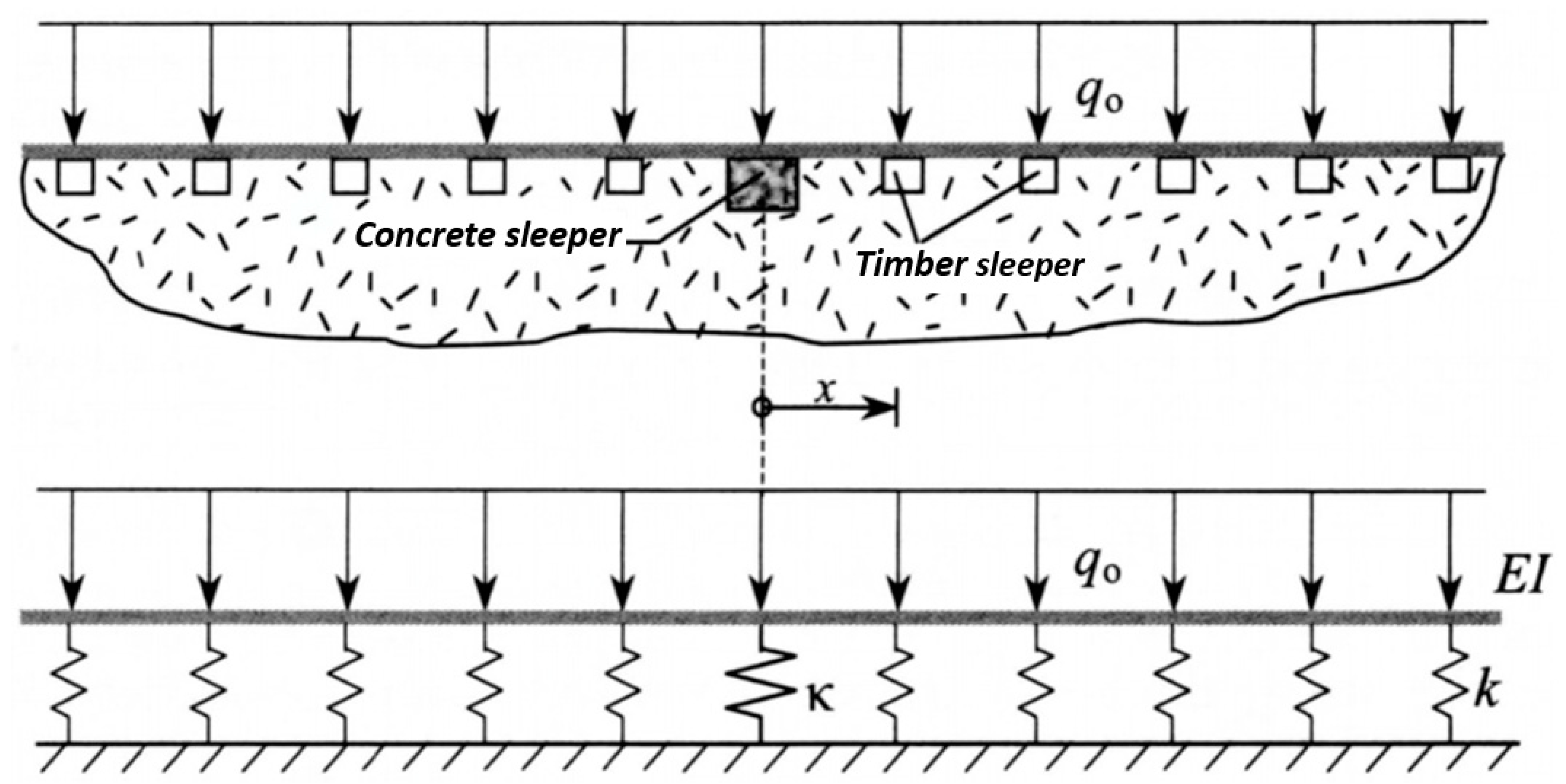
2. Background and Theory

Maintaining a consistent track modulus ensures that track performance meets the standard design and maintenance specifications (e.g., International Union of Railways (UIC) track performance evaluation criteria), and requires minimal maintenance interventions [13,14]. Fröhling [15] showed that vertical stiffness variations induce differential track settlements, resulting in accelerated deterioration of the railway track. Ensuring that sleeper support is consistent can also contribute to improved ride quality, and can minimize track and vehicle maintenance costs attributed to damage associated with variability in track stiffness. In this regard, stiffness transition zones are locations where abrupt changes in the track modulus occur due to a discontinuity in the track structure (e.g., between embankments and bridges or between different track configurations) [16], and a sizeable body of research has focused on providing a consistent track modulus to improve performance in these areas [17,18]. For example, Korea Code 14080 (KR C-14080) provides guidance on the maximum allowable change in the track modulus in a transition zone section [19]. In this guideline, the variance in the track modulus at the transition zone must be within the allowable range, which is commensurate with the maximum allowable train speed (Figure 1). This method considers the following factors: vibration acceleration of vehicle body, wheel load fluctuation, yield stress of rail fatigue, and uplifting force [19]. While the change in stiffness in typical transition zones is more abrupt and disruptive than sleeper-to-sleeper variation (approximately 42% between timber and concrete sleepers, and as much as 73% between regular track and an average bridge deck [20]), the comparison to interspersed concrete sleepers in timber sleeper track is still applicable.
Studies conducted on a Spanish high-speed line (HSL) indicate that maintenance at transitions to bridges or box culverts can be up to three to six times more frequent compared to open track [21]. This discontinuity at transitions can cause abnormal vibrations in both the vehicle and the track, which compromise ride comfort and safety due to the difference in the track impact factor [22]. Low track-support stiffness can result in the development of adverse track geometry. Under these conditions, the track structure is increasingly affected by vehicle loading, leading to loads that exceed the track strength and accelerate track deterioration [8,23,24]. Building on earlier findings in track transition areas, we investigated the difference in the track modulus due to the interspersed installation of EIC and timber sleepers.
To mitigate the negative effects of train operation and maintenance, careful consideration should be given when designing the track with different track materials. Various methods have been used to gradually change the track modulus (e.g., reinforcement rail, substructure solidification, reinforced roadbed layer, and changes to the timber-sleeper length and cross-sectional area) [25]. While the applications are quite different from the current practice of interspersing concrete and timber sleepers (Figure 2), the objective is the same—to maintain a consistent track modulus to minimize excessive vehicle and track loads.
Various methodologies for estimating a track’s structural behavior have been developed and documented. Pasternak’s method applies Winker’s model to consider the foundation based on the upper and lower spring layers and the shear layer [26]. Timoshenko’s foundation model considers the effect of transverse shear deflection resulting from an error in shear force and moment distribution, which can become significant in foundation beams with a small length-to-depth ratio in closely spaced discrete column loads [27]. A model developed by Kerr [28], which is based on Pasternak’s method and employs Reissner’s foundation model, has an advantage over other models because in the upper spring layer, no concentrated reactions or infinite reaction pressure can appear [28].
For this study’s comparative analysis of the effect of inserting EIC sleepers in continuous-welded rail timber-sleeper track, a beam on elastic foundation (BOEF) model developed by Kerr [29] was employed. This method, which is well-established in the international railway community, is known to be reasonably representative, and allows for determination of the track modulus (i.e., the stiffness of the spring k per unit length of track) [30].
In this model, a concrete sleeper is represented by a single spring with a constant κ , while the timber sleepers are represented by a Winkler base with a track modulus k (Figure 3) [31]. The adjacent wheels are not considered due to their negligible effect on the overall behavior of the system.
The corresponding governing equation for this model is:
E I w I V   +   k w ( x )   =   q 0
where w is the vertical deflection of the rail axis at x; EI is the vertical flexural stiffness of one rail; k is the track modulus (for one rail), and uniformly distributed load; q 0 is the general solution for w is as shown in Equation (2).
Based on the above model, the corresponding force that the rail exerts on the concrete sleeper is:
F c t = κ w ( 0 ) = κ q 0 k ( 1 κ 2 E I 4 β 3 + κ 2 E I ) = κ q 0 k ( 4 β 3 4 β 3 + κ 2 E I ) ,
whereas the corresponding force that the rail exerts on the timber sleeper is:
F q 0 = q 0 × a
Therefore, the effect of the inserted concrete sleeper is:
F c t F q 0 =   κ a k ( 1 1 + β κ / ( 2 k ) )
Based on the previous formulations and the common track property values listed in Table 1, the corresponding values of F c t / F q 0 can be determined for various values of κ (Table 2 and Figure 4).
The above analysis reveals that when a concrete sleeper replaces a timber sleeper, the higher stiffness of the concrete sleeper will result in that sleeper supporting proportionally higher rail-seat loads due to the difference in sleeper stiffness. According to this analysis, when a concrete sleeper is adjacent to a timber sleeper, the concrete sleeper can receive as much as five times more load than the adjacent timber sleepers (Kerr’s calculations are as follows: lim κ ( F c t / F q 0 ) =   2 β a = 5.076 ). However, Kerr’s analysis assumes that the concrete sleeper and its supporting structure are rigid. The typical track modulus value for mainline concrete-sleeper track is 41.38 N/mm/mm (6000 lbs./in./in.), which is twice as stiff as the typical timber-sleeper track modulus of 20.69 N/mm/mm (3000 lbs./in./in.) [32]. Considering this, and employing the same analysis methodology by Kerr, the load supported by the concrete sleeper can be approximately 1.37 times higher than the load supported by the timber sleepers. Regardless, the concrete sleeper will accept a greater magnitude vertical load, and will transfer a higher pressure to the ballast. These higher demands could lead to localized sleeper structural damage, ballast crushing, and/or substructure damage that would result in an overall poor track condition after the accumulation of tonnage.
The EIC sleeper used in this study attempts to reduce the differential stiffness between sleeper material types through an optimized structural design that reduces bending stiffness, and an innovative engineered rail seat plate and pad system.

3. Field Experimentation Methods

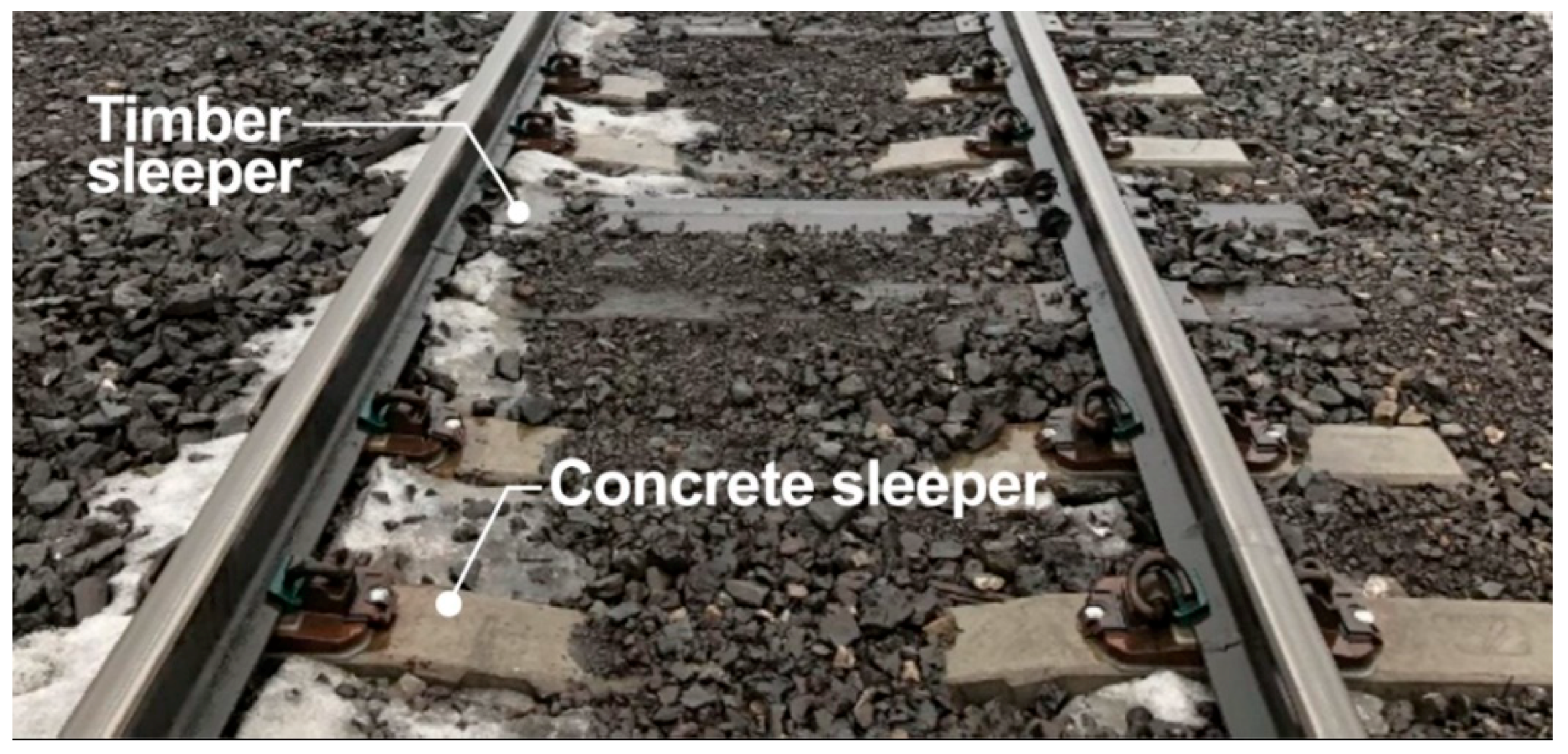
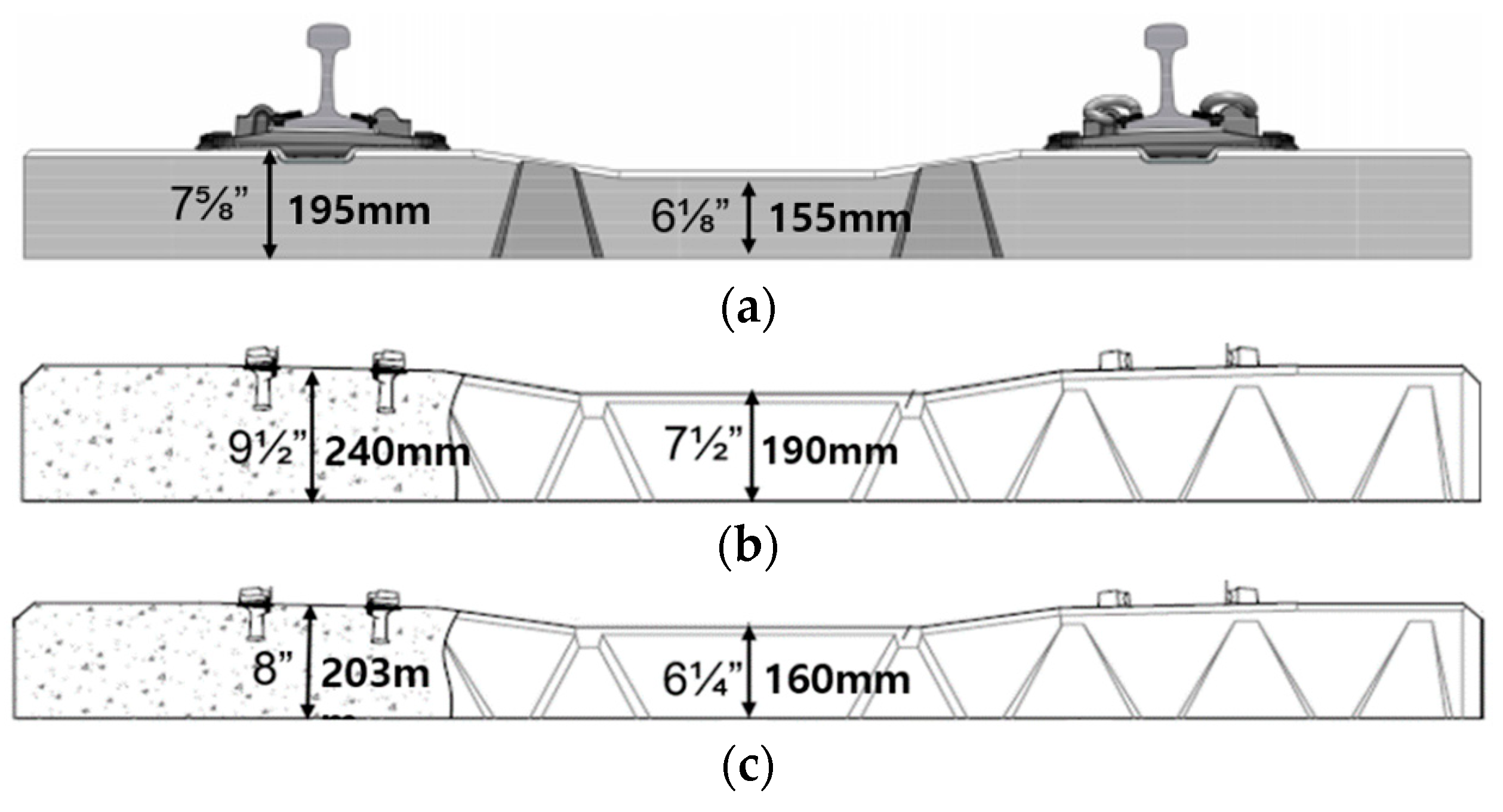
3.1. Engineered Interspersed Concrete (EIC) Sleeper

The EIC sleeper installed at the commuter-rail field test site (Figure 5a) had a smaller cross-sectional area, and consequently a smaller flexural rigidity, than the two typical concrete sleepers used for either heavy axle load (HAL) freight (Figure 5b) or light-rail transit (Figure 5c) applications in North America. The EIC sleeper featured a ductile plate and resilient pad positioned in the vertical load path, which reduced the sleeper’s stiffness. This reduced stiffness was engineered to be comparable to a timber sleeper, with the goal of preventing the various problems with stiffness heterogeneity that were mentioned previously.

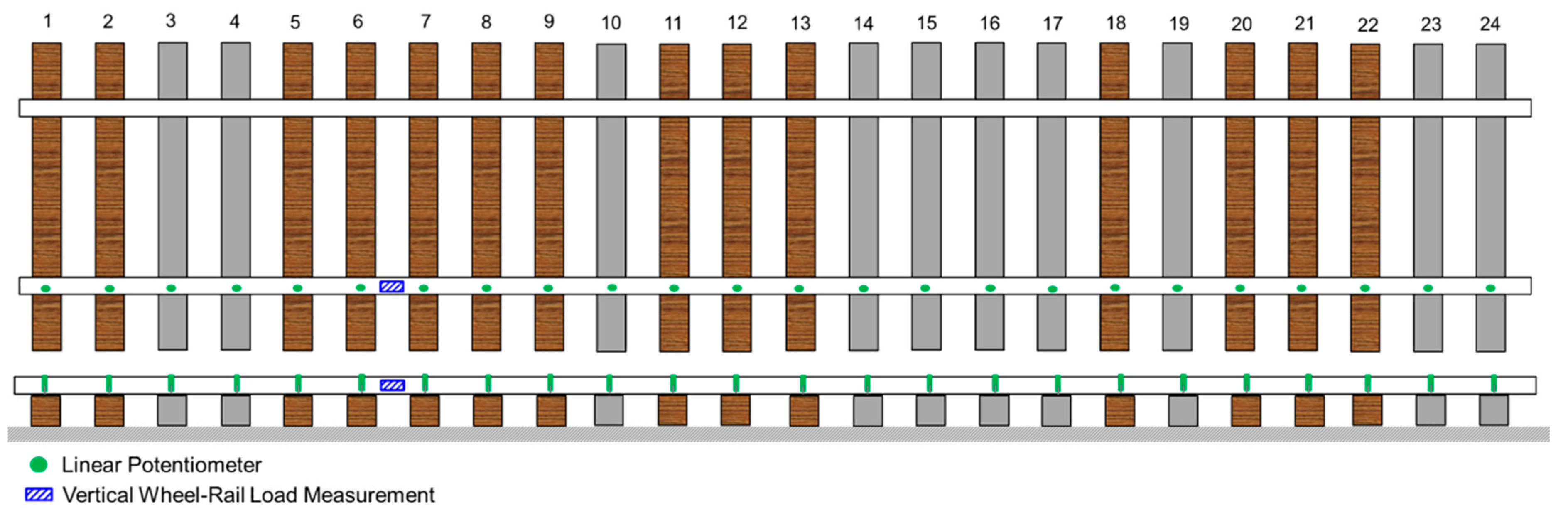
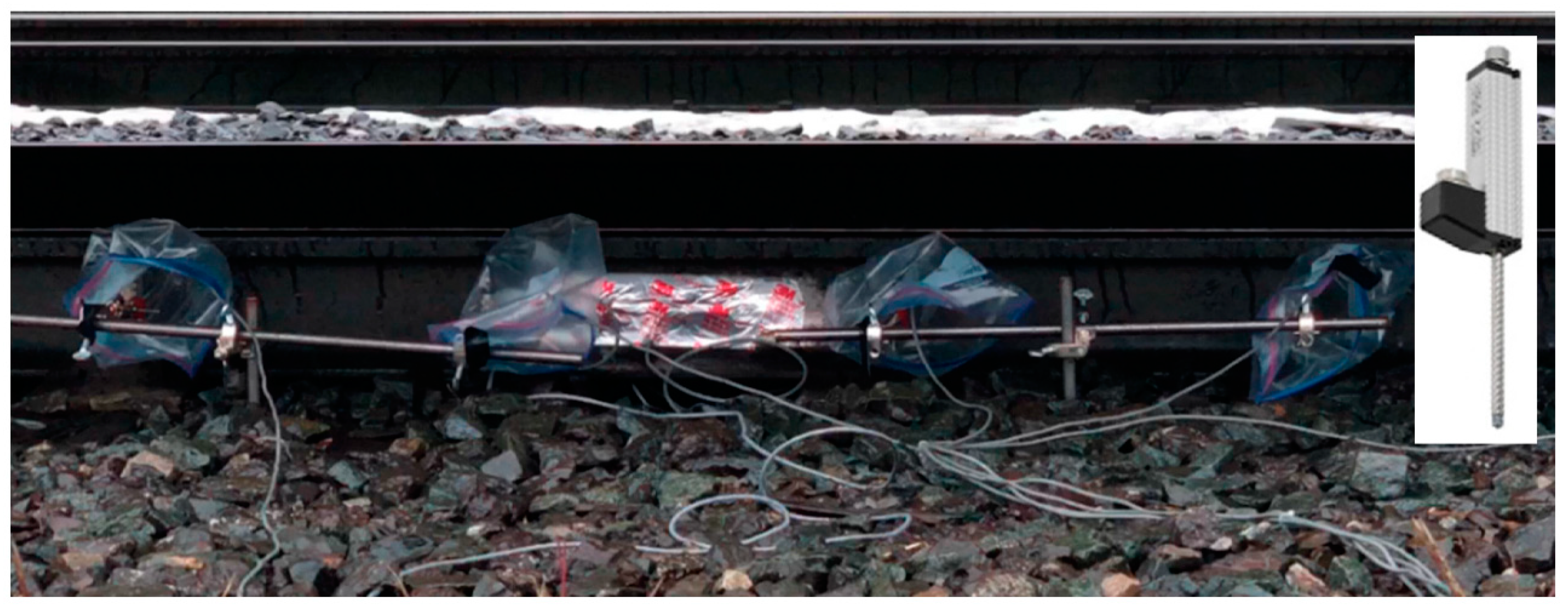
3.2. Field Site and Instrumentation

A field test zone was selected in a tangent track in which the timber sleepers had recently been replaced with EIC sleepers. A visual assessment showed evidence of ballast fouling in the test zone location, although drainage still appeared to function properly, as there was no standing water, and appropriate shoulders were still present. This selection of a single zone limited the variability in data due to substructure differences, while capturing various installation conditions, including different permutations of interspersed timber and EIC sleepers (Figure 6). The instrumentation was deployed to quantify both vertical wheel–rail input loads and vertical track displacements.
Vertical wheel–rail forces were quantified using strain-gauge-based industry-standard circuits as described by Edwards [33]. The installation of strain gauges on the rail required the welding of gauges to the rail using a portable strain-gauge welding unit. This process involved grinding the web and base of the rail to remove rust and expose pure metal, clamping a ground wire to the base of the rail, and placing the strain gauge and using the welding electrode to send current through the material, which welded the strain gauge to the rail. These gauges were subsequently calibrated using a loading frame with calibrated load cell, allowing strains to be used to quantify vertical wheel–rail loads. During the calibration, vertical loads of up to 200 kN (45,000 lbf) were applied to the rail while the voltage from the strain bridge was simultaneously recorded.
Vertical track displacements were measured to quantify the track modulus on both EIC sleepers and timber sleepers. Displacement transducers, which are linear potentiometers (Figure 7), were used to measure the track displacement at the rail base relative to the ground. This was accomplished by driving support rods 40 mm (5/8 in.) in diameter to refusal in the field-side crib between the sleepers. The potentiometers had a maximum stroke length of 25 mm (1 in.), and were accurate to ±0.002 mm (7.9 × 10 5 in.). The calibration factors were provided by the manufacturer and further checked before installation using a calibration height gauge.
All data were recorded using a National Instruments (NI) Compact Data Acquisition System (cDAQ) via a LabVIEW virtual instrument (VI) developed for the instrumentation used in this experiment. The data were collected at a sampling rate of 2.5 kHz to ensure the maximum wheel–rail load was captured.

3.3. Single-Point Load Method for Track Modulus Calculation

The track modulus values were calculated using the single-point load method, which was developed and documented by Selig and Waters [34]. This method requires knowledge of the rail’s sectional properties, the wheel load, and the track deflection. Using these inputs, and based on the BOEF fundamentals, the track modulus was computed. The equation used to calculate track modulus is shown below:
k = ( P w m ) 4 / 3 ( 64 E I ) 1 / 3
where k is the track modulus (kN/mm, lb . / in . / in . ) ;   w m is the maximum track deflection (mm, in); P is the wheel load (kN, lb . ); E is the modulus of elasticity of steel (MPa, psi ) = 21 0 , 000   MPa , 30 × 106 psi; I is the moment of inertia of rail ( mm 4 ,   in 4 ) = 36,700,000   mm 4 , 88.2   in 4 (132RE Rail); E I is the flexural rigidity of the rail.
Other methods to calculate the track modulus require additional knowledge of the entire deflection basin and its area, which is more complicated to quantify analytically. For this study, the single-point load method was deemed appropriate. This study required a deviation from the traditional single-point load method for determining the track modulus because of the interaction between the wheels applying loads adjacent to the point in which the peaks were extracted, so there was no true single point that applied the load. For the rolling stock used, this interaction effect of the adjacent wheels was negligible (approximately 0.8% based on the BOEF analysis). Additionally, the interaction influenced both the EIC sleepers and timber sleepers in the same manner, which mitigated its potential negative impact on the results, which were largely comparative in nature.
For the single-point load method, there is typically no adjustment for potential slack in the system due to gaps beneath the sleepers. While this could lead to errors based on visual deflection observations that appeared to indicate gaps were present, the large number of sleepers for which data were collected (23 total) increased our confidence in the data, and quantified the representative behavior of each sleeper type while mitigating the presence of gaps below any given crosstie.

4. Results and Discussion

The data were collected from a total of 10 revenue-service train passes at approximately 64 km/h (40 mph). The trains included a combined 12 locomotives and 116 passenger coaches, totaling 512 axle passes. A total of 23 rail-base displacement channels were recorded (the sensor placed on sleeper 11 malfunctioned), and the corresponding data (11,236 data points) were used to generate the figures below. The data were found to have high signal-to-noise ratios and were considered clean (Figure 8). As expected, the peaks in the two data streams were generated when a wheel was directly above each sleeper (in the case of displacements) and in the center of the crib (in the case of the wheel-load bridge). The peaks from the load and displacement channels were extracted from the data primarily through manual peak selection, with some assistance provided using developed MATLAB algorithms.

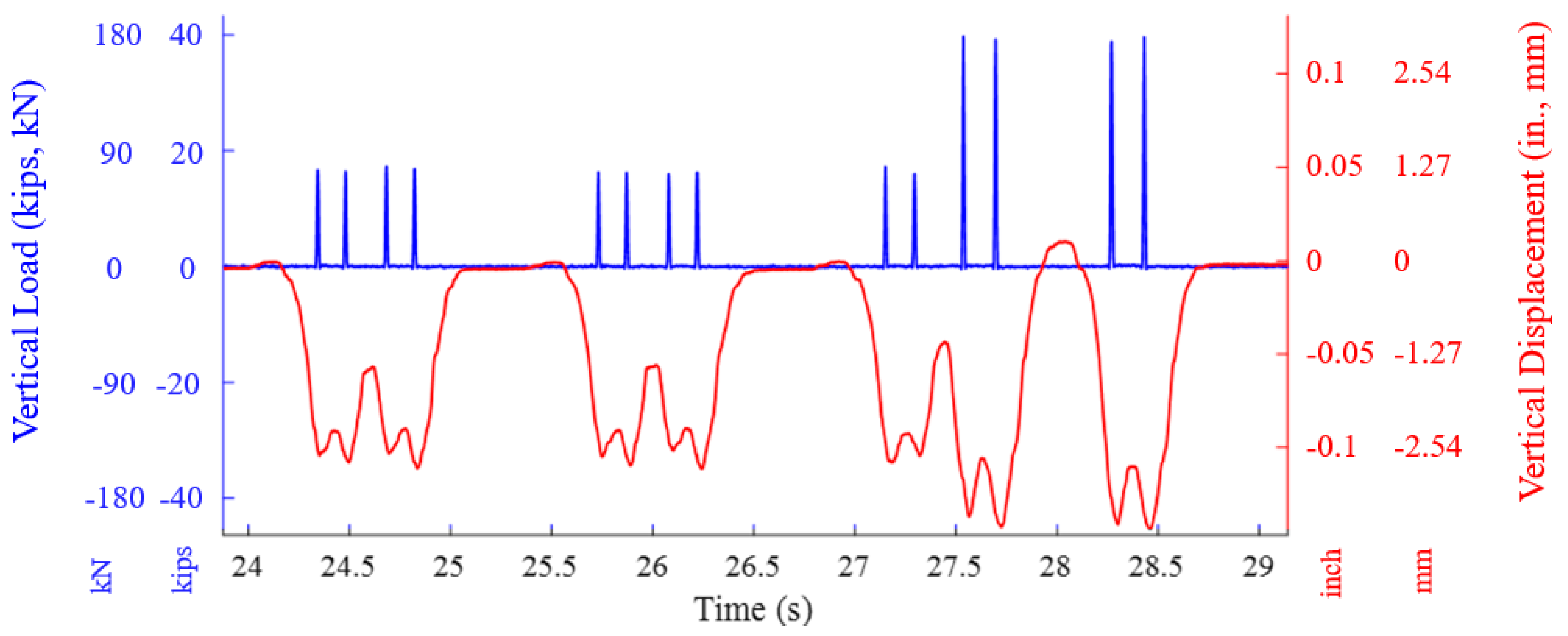
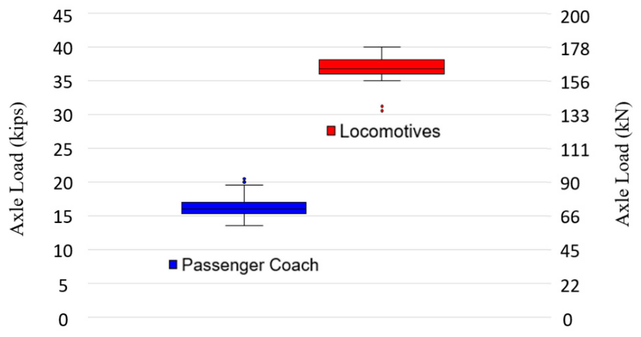
Wheel Load and Displacement Comparison Results

The distribution of wheel loads measured at the field site for both passenger coaches and locomotives matched the expected loads based on the nominal static load ratings that were acquired previously (Figure 9).
The data showed a minimal difference in track displacements between the two sleeper types (Figure 10) independent of load source (passenger coach or locomotive). The observed median displacement values under the passenger coaches were 2.26 mm (0.089 in.) and 2.21 mm (0.087 in.) for timber and EIC sleepers, respectively. The observed median displacement values under the locomotives were 2.70 mm (0.1062 in.) and 2.74 mm (0.1078 in.) for timber and EIC sleepers, respectively. The locomotive data were also useful because they provided a proxy for the expected behavior of these sleeper types under loaded HAL freight-train loads.
The field results (Figure 11) showed that the sleepers’ positional variability exceeded that of the observed variability between sleeper types. For example, the displacement results of the first ten sleepers ranged from 1.22 mm (0.048 in.) to 3.02 mm (0.119 in.). Within this range, both the minimum and maximum peak values were recorded for timber sleepers. The highest median values were measured in sleepers 21 to 24, ranging from 3.81 mm (0.150 in.) to 4.32 mm (0.170 in.), and included both sleeper types. When we compared sleeper-displacement results alone, it was difficult to distinguish variability between timber and EIC sleepers, a finding that was also documented in prior research [9].
Using both the loading data and the corresponding track displacements, the track-modulus values for all axles were determined using the single-point load method (Figure 12). As discussed in Section 3, any potential contribution for slack in the system was mitigated by capturing many replicate sleepers (23 in total). The timber-sleeper and EIC-sleeper median track-modulus values were 12.95 N/mm/mm (1878 lbs./in./in.) and 12.79 N/mm/mm (1855 lbs./in./in.), respectively. The five-sleeper moving-average track modulus result showed a minimal difference in track response to load when the rail was supported by either a timber sleeper or an EIC sleeper (Figure 13). The calculated results are not independent measurements; they are dependent on the specific site conditions and interspersed arrangement, so the modulus of the EIC sleepers was dependent on the adjacent sleepers, and vice versa. Nevertheless, the obtained results indicated that the EIC sleepers provided a similar stiffness response to the timber sleepers in this interspersed installation.

5. Conclusions

This study assessed a section of track with interspersed timber sleepers and EIC sleepers that were designed to replicate timber-sleeper stiffness, and provided an analytical evaluation of the expected stiffness variation between traditional concrete sleepers, which can lead to an accelerated deterioration of the railway track and its components. Based on Kerr’s structural-analysis method, the conducted theoretical analysis demonstrated that the expected variation in the track-modulus value between sleeper types caused a difference in the load-support distribution. A field investigation was used to evaluate the performance of an interspersed sleeper structure composed of EIC and timber sleepers. Based on this background, the field experimentation results, and the evaluation of each rail-seat performance, the findings and conclusions were:
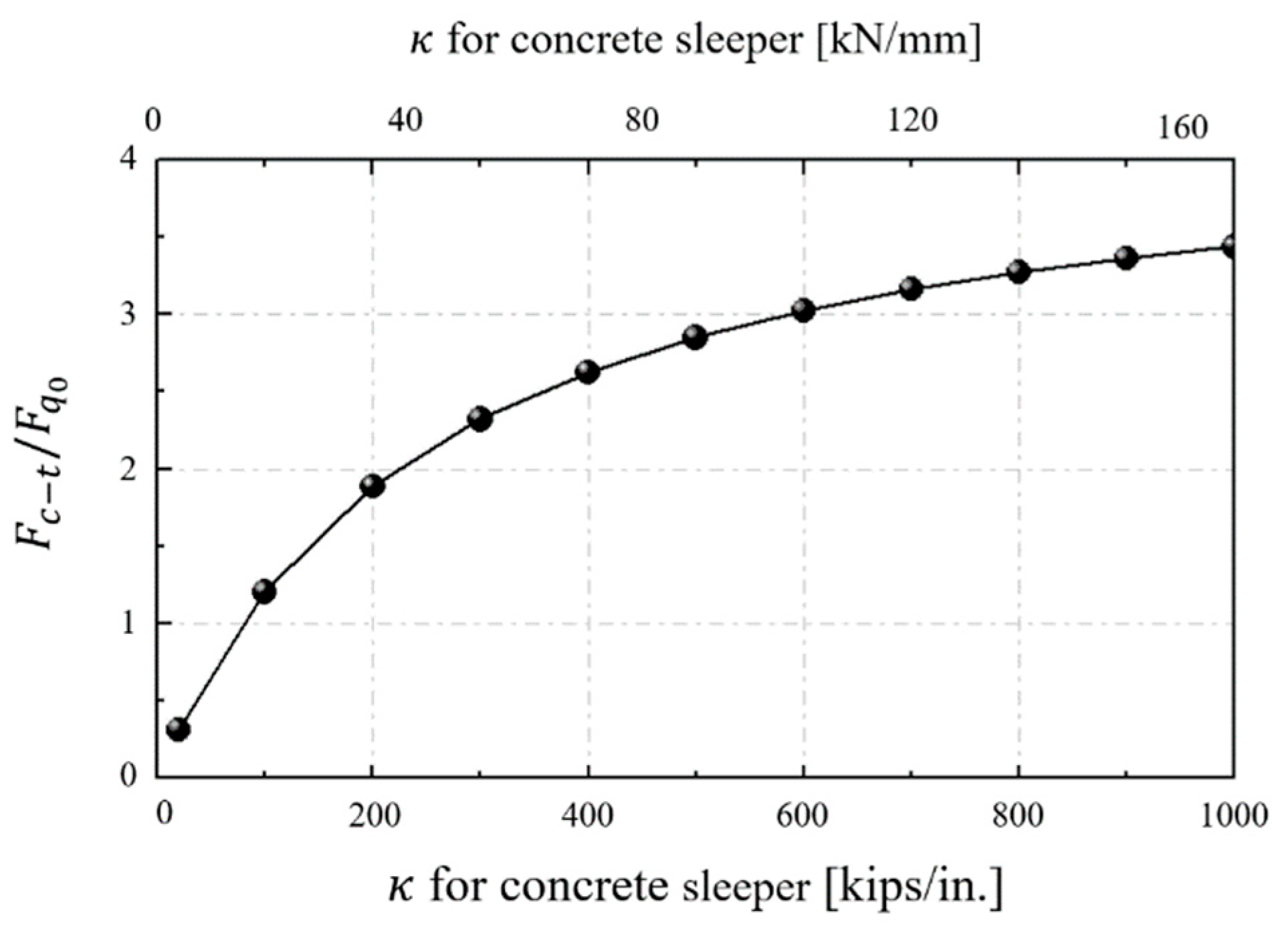
  • The theoretical analysis showed that interspersed standard concrete sleepers placed within a timber-sleeper track can experience a load up to five times greater than the load supported by the adjacent timber sleepers.
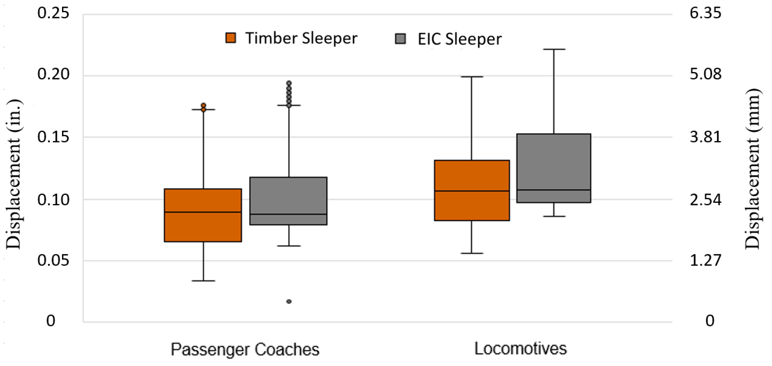
  • Based on measurements of sleeper displacement, both timber sleepers and EIC sleepers presented a similar track response. For timber sleepers, the median displacement value was 2.26 mm (0.089 in.), and for EIC sleepers, it was 2.21 mm (0.087 in.).
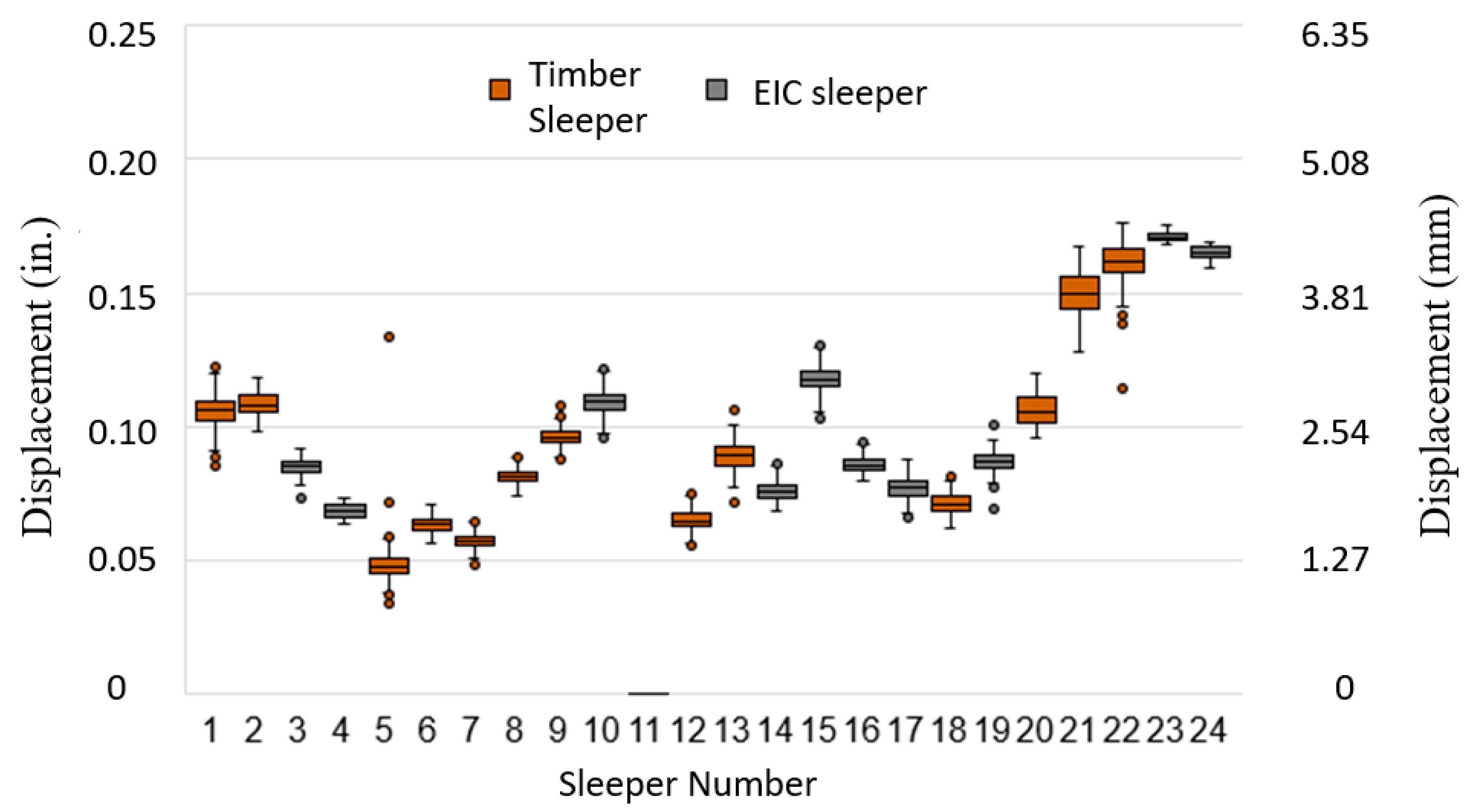
  • The track-displacement results from the field instrumentation ranged from 1.22 mm (0.048 in.) to 4.32 mm (0.170 in.) for all timber sleepers.
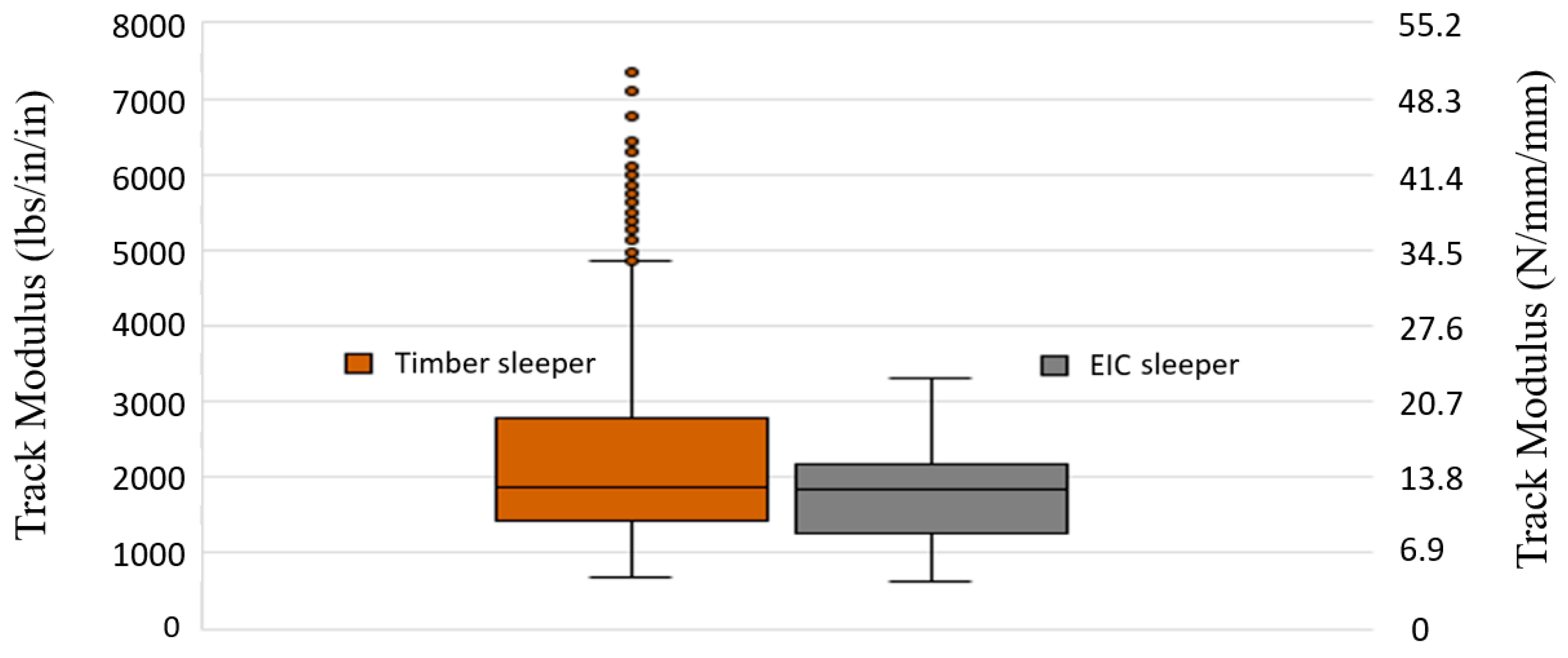
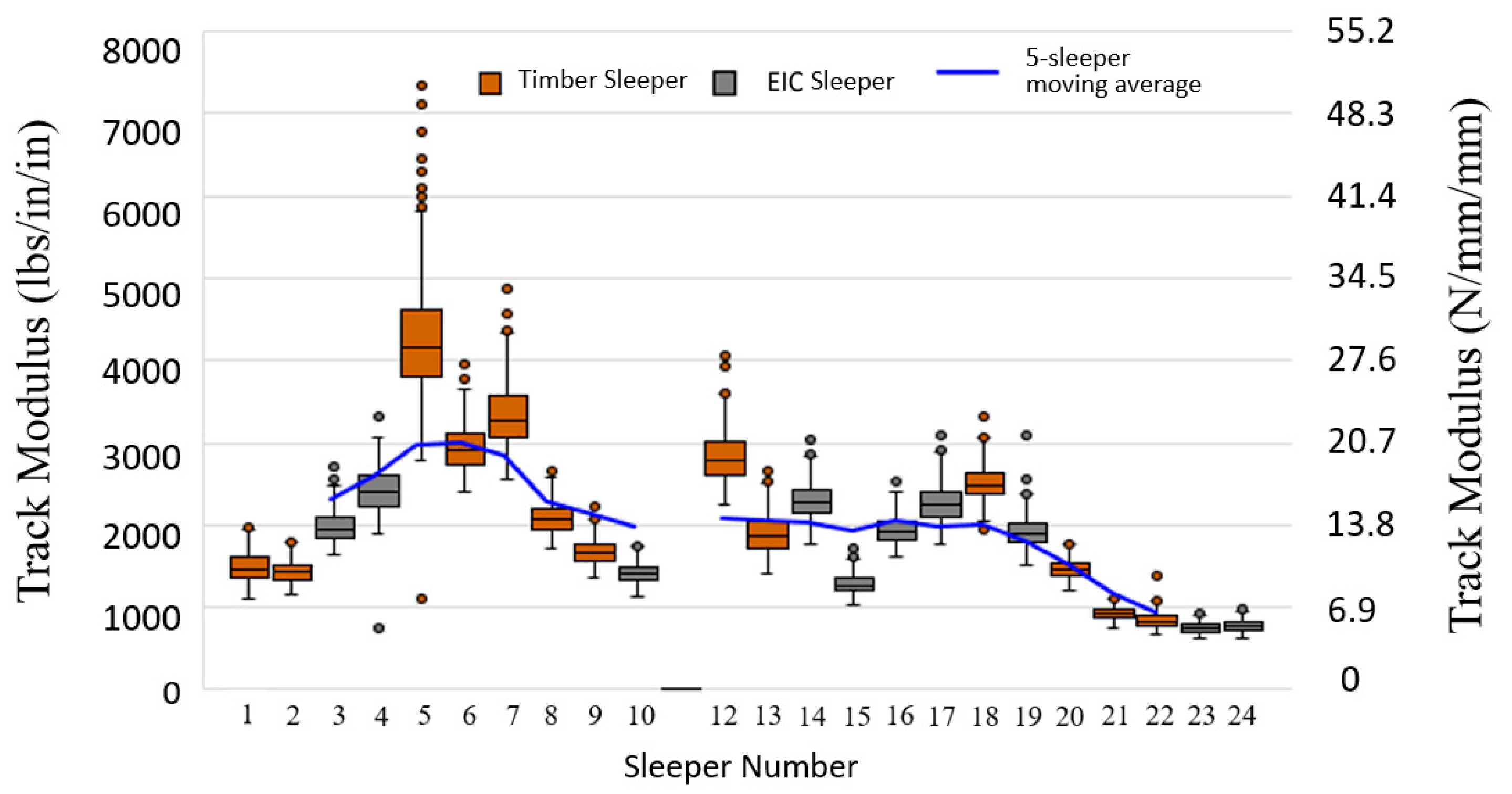
  • The track-modulus results indicated a median modulus of 12.95 N/mm/mm (1878 lbs./in./in.) for the timber sleepers, and 12.79 N/mm/mm (1855 lbs./in./in.) for the EIC sleepers.
  • The variance in performance for the two sleeper types cannot be clearly distinguished with track-displacement or modulus results, which provides a favorable indication for future field performance.
Based on the results, the desired performance of the EIC sleepers in maintaining consistent track modulus was demonstrated for this application and set of track conditions. This homogeneity in modulus is crucial to ensure a smooth ride quality and minimize track maintenance due to geometry deviations. The principal design characteristics that contributed to the EIC sleeper’s performance were the reduced cross-sectional area and resulting reduction in flexural rigidity, and the resilient rail-seat plate system, with the latter providing most of the stiffness reduction. This study showed that properly engineered concrete sleepers can be interspersed in timber-sleeper track to achieve a similar track response. Nevertheless, the exact results for the track modulus obtained in this study are not entirely independent, and should not be extrapolated to other applications/locations without further study. Future work should include field experimentation in locations with a higher overall track modulus and different arrangements of the sleeper installation.

Author Contributions

Conceptualization, A.d.O.L. and J.R.E.; methodology, A.d.O.L. and M.S.D.; data collection, A.d.O.L., J.R.E. and M.S.D.; data processing, A.d.O.L. and J.L.; writing—original draft preparation, A.d.O.L., J.R.E., J.L.; writing—review and editing, A.d.O.L., J.R.E. and M.S.D.; supervision, J.R.E.; project administration, A.d.O.L.; funding acquisition, J.R.E. and A.d.O.L. All authors have read and agreed to the published version of the manuscript.

Funding

This research was primarily supported through funding from the National University Rail Center (NURail). The positions presented within this paper represent those of the authors and not necessarily those of the US Department of Transportation.

Institutional Review Board Statement

Not applicable.

Informed Consent Statement

Not applicable.

Data Availability Statement

Restrictions apply to the availability of these data. Data are owned by a sponsoring agency but may be available from the authors with permission of the sponsoring agency.

Conflicts of Interest

The authors declare no conflict of interest.

References

  1. Matias, S.R.; Ferreira, P.A. Railway slab track systems: Review and research potentials. Struct. Infrastruct. Eng. 2020, 16, 1635–1653. [Google Scholar] [CrossRef]
  2. Railway Tie Association (RTA). Available online: https://www.rta.org/faq (accessed on 12 November 2020).
  3. Qiao, P.; Davalos, J.F.; Zipfel, M.G. Modeling and optimal design of composite-reinforced wood railroad crosstie. Compos. Struct. 1998, 41, 87–96. [Google Scholar] [CrossRef]
  4. McCombe, E.; Ryan, M. Development of sleeper strategies focusing on timber sleeper replacement. In Proceedings of the AusRAIL PLUS 2003, Investing in Australian Rail-Strategies and Solutions, Sydney, Australia, 17–19 November 2003. [Google Scholar]
  5. Alexander, H.L. Railroad Decision Support Tools for Track Maintenance. Ph.D. Thesis, University of Illinois at Urbana-Champaign, Champaign, IL, USA, 2017. [Google Scholar]
  6. Bastos, J.C.; Dersch, M.S.; Edwards, J.R. Statistical Prediction of Center Negative Bending Capacity of Pretensioned Concrete Crossties. J. Transp. Eng. Part A Syst. 2020, 146, 04019074. [Google Scholar] [CrossRef]
  7. Alvaro, E.C.R.; Qian, Y.; Edwards, J.R.; Dersch, M.S. Analysis of the Temperature Effect on Concrete Crosstie Flexural Behavior. Constr. Build. Mater. 2019, 196, 362–374. [Google Scholar]
  8. Bastos, J.C.; Alejandro, Á.R.; Dersch, M.S.; Edwards, J.R.; Barkan, C.P.L. Laboratory Characterization of Structural Capacity of North American Heavy Haul Concrete Crossties. Transp. Res. Rec. J. Transp. Res. Board 2018, 2672, 116–124. [Google Scholar] [CrossRef]
  9. Edwards, J.R.; Canga, R.A.E.; Cook, A.A.; Dersch, M.S.; Qian, Y. Quantifying bending moments in rail-transit concrete sleepers. J. Transp. Eng. Part A Syst. 2018, 144, 04018003. [Google Scholar] [CrossRef] [Green Version]
  10. Naaman, A.E. Prestressed Concrete Analysis and Design: Fundamentals, 2nd ed.; Techno Press: Ann Arbor, MI, USA, 2004. [Google Scholar]
  11. Ngamkhanong, C.; Chuah, M.W.; Sakdirat, K. Buckling Analysis of Interspersed Railway Tracks. Appl. Sci. 2020, 10, 3091. [Google Scholar] [CrossRef]
  12. Celestin, N. Influence of Spatial Variations of Railroad Track Stiffness and Material Inclusions of Fatigue Life. Ph.D. Thesis, University of Nebraska, Lincoln, NE, USA, 2015. [Google Scholar]
  13. Cai, Z.; Raymond, G.P.; Bathurst, R.J. Estimate of static track modulus using elastic foundation models. J. Transp. Res. Board 1994, 1470, 65–72. [Google Scholar]
  14. Arnold, R.; Lu, S.; Hogan, C.; Farritor, S.; Fateh, M.; El-Sibaie, M. Measurement of vertical track modulus from a moving railcar. In Proceedings of the American Railway Engineering and Maintenance-of-Way Association Annual Conference, Louisville, KY, USA, 17–20 September 2006. [Google Scholar]
  15. Fröhling, R.D. Deterioration of Railway Track Due to Dynamic Vehicle Loading and Spatially Varying Track Stiff-Ness. Ph.D. Thesis, University of Pretoria, Pretoria, South Africa, 1997. [Google Scholar]
  16. Fortunato, E.; Paixão, A.; Calçada, R. Railway Track Transition Zones: Design, Construction, Monitoring and Numerical Modelling. Int. J. Railw. Technol. 2013, 2, 33–58. [Google Scholar] [CrossRef]
  17. Buddhima, I.; Muhammad, B.S.; Trung, N.; Antonio, G.C.; Richard, K. Improved performance of ballasted tracks at transition zones: A review of experimental and modelling approaches. Transp. Geotech. 2019, 21, 100260. [Google Scholar]
  18. Wang, H. Measurement, Assessment, Analysis and Improvement of Transition Zones in Railway Track. Ph.D. Thesis, Delft University of Technology, Delft, The Netherlands, 2019. [Google Scholar]
  19. Korea Rail Network Authority (KR). KR C-14080: Interaction Between Track, Vehicle, Signal, Structure, Electricity; KR: Daejeon, Korea, 2012. [Google Scholar]
  20. Plotkin, D.; Davis, D. Bridge Approaches and Track Stiffness; Federal Railroad Administration: Washington, DC, USA, 2008.
  21. López Pita, A.; Teixeira, P.F.; Casas-Esplugas, C.; Ubalde, L. Deterioration in geometric track quality on high speed lines: The experience of the Madrid-Seville high speed line (1992–2002). In Proceedings of the TRB 85th Annual Meeting, Washington, DC, USA, 22–26 January 2006. [Google Scholar]
  22. Sanudo, R.; Dell’Oli, L.; Casado, J.A.; Carrascal, I.A.; Diego, S. Track transitions in railways: A review. Constr. Build. Mater. 2016, 112, 140–157. [Google Scholar] [CrossRef]
  23. Priest, J.A.; Powrie, W. Determination of Dynamic Track Modulus from Measurement of Track Velocity during Train Passage. J. Geotech. Geoenviron. Eng. 2009, 135, 1732–1740. [Google Scholar] [CrossRef]
  24. American Railway Engineering and Maintenance-of-Way Association (AREMA). Manual for Railway Enginnering; AREMA: Lanham, MD, USA, 2017.
  25. Lee, K.Y. A Study Improvement the Transition Area of Bridge and Embankment Using Reinforced Rail and Ballast Stabilizer. Master’s Thesis, Seoul National University of Science and Technology, Seoul, Korea, 2014. [Google Scholar]
  26. Radeş, M. Dynamic analysis of an inertial foundation model. Int. J. Solids Struct. 1972, 8, 1353–1372. [Google Scholar] [CrossRef]
  27. Avramidis, I.E.; Morfidis, K. Bending of beams on three-parameter elastic foundation. Int. J. Solids Struct. 2006, 43, 357–375. [Google Scholar] [CrossRef] [Green Version]
  28. Kerr, A.D. A study of a new foundation model. Acta Mech. 1962, 1, 135–147. [Google Scholar] [CrossRef] [Green Version]
  29. Kerr, A.D. The determination of the track modulus k for the standard track analysis. In Proceedings of the American Railway Engineering and Maintenance-of-Way Association Annual Conference, Washington, DC, USA, 24 September 2002. [Google Scholar]
  30. Tzanakakis, K. The Railway Track and Its Long Term Behaviour: A Handbook for a Railway Track of High Quality; Springer: Berlin/Heidelberg, Germany, 2013. [Google Scholar]
  31. Winkler, E. Die Lehre von der Elasticitaet und Festigkeit mit Besondere Ruecksicht auf ihre Anwendung in der Technik, fuer Polytechnische Schuhlen, Bauakademien, Ingenieure, Maschienenbauer, Architecten, etc.; H. Dominicus: Prague, Czech Republic, 1867. [Google Scholar]
  32. Rapp, C.T.; Dersch, M.S.; Edwards, J.R.; Barkan, C.P.L.; Wilson, B.; Mediavilla, J. Measuring Concrete Crosstie Rail Seat Pressure Distribution with Matrix Based Tactile Surface Sensors. In Proceedings of the American Railway Engineering and Maintenance-of-Way Association Annual Conference, Chicago, IL, USA, 16–19 November 2012. [Google Scholar]
  33. Edwards, J.R.; Aaron, C.; Dersch, M.S.; Qian, Y. Quantification of rail transit wheel loads and development of improved dynamic and impact loading factors for design. J. Rail Rapid Transit 2018, 232, 2406–2417. [Google Scholar] [CrossRef]
  34. Selig, E.T.; Waters, J.M. Track Geotechnology and Substructure Management; Thomas Telford Services: London, UK, 1994. [Google Scholar]
Figure 1. The allowable ratio of the track modulus difference depending on train speed [19].
Applsci 11 00261 g001
Figure 2. Installation of timber and engineered interspersed concrete (EIC) sleepers.
Applsci 11 00261 g002
Figure 3. The analytical model of the interspersed concrete sleeper in a continuous welded rail track [29].
Applsci 11 00261 g003
Figure 4. The result of F c t / F q 0 depending on the spring constant of the concrete sleeper ( κ ) [29].
Applsci 11 00261 g004
Figure 5. A comparison of (a) an EIC sleeper; (b) a typical North American freight HAL concrete sleeper; (c) a typical North American light rail transit concrete sleeper.
Applsci 11 00261 g005
Figure 6. The test zone, with the timber and EIC sleepers shown with the instrumentation layout.
Applsci 11 00261 g006
Figure 7. The linear potentiometer and rod system used to measure the vertical track displacement.
Applsci 11 00261 g007
Figure 8. An example of track displacement and wheel load data.
Applsci 11 00261 g008
Figure 9. The distribution of the wheel loads measured at site.
Applsci 11 00261 g009
Figure 10. Comparison of the track displacement between the timber and EIC sleepers.
Applsci 11 00261 g010
Figure 11. The displacement results for each individual sleeper (passenger coaches only).
Applsci 11 00261 g011
Figure 12. Comparison of the track modulus between the timber and EIC sleepers, considering all measured locomotive and passenger coach field data.
Applsci 11 00261 g012
Figure 13. The track modulus results for each individual sleeper instrumented in the field test zone.
Applsci 11 00261 g013
Table 1. The values of various parameters for calculating the effect ratio [32].
RailModulus of ElasticityMoment of
Inertia
Wood Timber Modulus, kSleeper
Spacing
Concrete   Sleeper   Modulus ,   κ
132RE210,000 MPa36,700,000   mm 4 20.69 N/mm/mm508 mmVariable
30,000,000 psi88.2   in . 4 3000 lbs . / in . / in . 20 in.
Table 2. The calculation result of F c t / F q 0 for various values of κ .
κ 1.75 kN/mm
10 kips/in.
17.51 kN/mm
100 kips/in.
43.78 kN/mm
250 kips/in.
87.56 kN/mm
500 kips/in.
175.13 kN/mm
1000 kips/in.
F c t / F q 0 0.1601.2042.1242.8513.440
Publisher’s Note: MDPI stays neutral with regard to jurisdictional claims in published maps and institutional affiliations.

