Article

Parallel Complex Quadrature Spatial Modulation

1
Future Convergence Engineering, Department of Electrical, Electronics and Communication Engineering, Korea University of Technology and Education, Cheonan 31253, Korea
2
Department of Computer Science, Northeastern Illinois University, 5500 N St. Louis Avenue, Chicago, IL 60625, USA
*
Authors to whom correspondence should be addressed.
Appl. Sci. 2021, 11(1), 330; https://doi.org/10.3390/app11010330
Submission received: 3 November 2020 / Revised: 22 December 2020 / Accepted: 24 December 2020 / Published: 31 December 2020
(This article belongs to the Section Electrical, Electronics and Communications Engineering)

Abstract

:
In this paper, we propose a new multiple-input multiple-output (MIMO) transmission scheme, called parallel complex quadrature spatial modulation (PCQSM). The proposed technique is based on the complex quadrature spatial modulation (CQSM) to further increase the spectral efficiency of the communication system. CQSM transmits two different complex symbols at each channel use. In contrast with CQSM, the new transmission scheme splits the transmit antennas into groups, and modulates the two signal symbols using the conventional CQSM before transmission. Based on the selected modulation order and the number of possible groups that can be realized, the incoming bits modulate the two signal symbols and the indices of the transmit antennas in each group. We demonstrated that while the complexity and performance of the proposed scheme is the same as that of CQSM, the number of required transmit antennas is significantly reduced. The proposed PCQSM achieves such a benefit without requiring any additional radio frequency (RF) chains. The results obtained from Monte Carlo simulation showed that at a Bit Error Rate (BER) of 10 4 , the performance of the PCQSM with two antenna groups closely matches that of CQSM, and outperformed quadrature spatial modulation (QSM) and parallel quadrature spatial modulation (PQSM) by over 0.7 dB. As the number of antenna groups increased to 4, the BER performance of PCQSM with reduced number of transmit antenna and modulation order matches that of QSM. The BER of the proposed scheme using maximum likelihood (ML) receiver is also analyzed theoretically and compared with the BER obtained via simulations.

1. Introduction

Multiple-input multiple-output (MIMO) techniques have the potential to meet the high data rate demands of the future wireless communication generations [1]. Index modulation (IM) is a group of MIMO techniques that utilizes the indices of available communication systems’ resources to convey information bits to the receiver [2]. These indices can be physical antennas [3], spreading codes [4], polarities [5], sub-carriers [6], rotation angles [7], and virtual channels [8], among others. At each channel use, only one or a subset of a given resources is activated. Therefore, IM techniques provide an energy efficient advantage to the communication systems over the conventional spatial multiplexing MIMO.
Spatial modulation (SM) is an IM technique, where only one antenna is activated to transmit a quadrature amplitude modulation (QAM)/phase shift keying (PSK) signal symbol at each channel use [3,9]. Both the antenna index and signal symbol convey information to the receiver. Therefore, the SM needs only a single radio frequency (RF) chain at the transmitter and the system avoids inter-channel interference. A drawback of the SM is the exponential growth of the number of transmit antennas to increase the spectral efficiency.
Several SM schemes were proposed to improve the spectral efficiency while keeping the transmitter requirements relatively simple. Generalized spatial modulation (GSM) reduces the number of required transmit antennas to achieve a given spectral efficiency by transmitting a signal symbol from a combination of two or more transmit antennas at each channel use [10]. Multiple active SM (MA-SM) uses antenna combinations to transmit independent signal symbols from each active antenna [11]. As such, MA-SM compromises the system’s complexity to achieve higher multiplexing gain. Parallel SM (PSM) splits the antenna set into equal-size subsets to transmit a single signal symbol [12,13] or independent signal symbols [14,15] from each antenna subset. The constellation design of the PSM with one signal symbol is discussed in [16].
Quadrature spatial modulation (QSM) exploits the in-phase and quadrature component of the transmit antennas to convey additional information through the spatial dimension [17]. At each channel use, the real and imaginary part of a modulated symbol is transmitted on the in-phase and quadrature component of any of the transmit antennas, respectively. The parallel implementation of the QSM with one symbol and independent symbols is proposed in [18,19], respectively. Improved QSM (IQSM) transmits the real and imaginary parts of two signal symbols, respectively, through the in-phase and quadrature dimensions, using combinations of two antennas [20]. Compared to the IQSM, the authors of [21] introduce double QSM and parallel IQSM to reduce the required number of transmit antennas without additional number of RF chains.
In complex QSM (CQSM), two complex symbols are transmitted through any available transmit antennas, at each channel use [22]. To avoid ambiguity at the receiver, the first and second signal symbol is drawn from a conventional QAM/PSK constellation and an optimally rotated one, respectively. The performance of the CQSM was improved in [23], and the constellation design of the improved CQSM was investigated in [24]. Moreove, generalized implementations of the CQSM was proposed in [25].
To further exploit the benefits of the CQSM system, a parallel CQSM (PCQSM) is proposed in this paper. PCQSM divides the group of transmit antennas into equal-size subgroups to apply the CQSM in each group independently, using the same two signal symbols. As such, PCQSM requires two RF chains, keeping the same CQSM hardware requirements. Similar to the CQSM, the signal symbols are drawn from distinct constellations, where the second constellation is a rotated version of the first. The optimal rotation angles that minimize the error rate are obtained offline through extensive Monte Carlo simulations for each system configuration. The merits of the PCQSM are summarized in the following.
  • The PCQSM increases the spatial spectral efficiency linearly with the number of antenna subgroups. As such, the PCQSM system extensively reduces the required number of transmit antennas to achieve a certain spectral efficiency. For example, to achieve 24 bits/s/Hz, the PCQSM requires 992, 224, and 32 less transmit antennas in contrast to QSM, CQSM, and PQSM, respectively.
  • For the same number of transmit antennas, the PCQSM uses lower modulation order, and therefore achieves better bit error rate (BER) performance. Compared to the PQSM, our proposed scheme has a signal-to-noise ratio (SNR) gain of 4 dB, while using two and four subgroups.
The rest of this paper is structured as follows. Section 2 describes the system model and related works. The proposed parallel complex quadrature spatial modulation is discussed in Section 3. The performance analysis of the proposed scheme is analytically derived in Section 4. The receiver complexity of PCQSM is analyzed in Section 5. Simulations results are presented and discussed in Section 6. Last, Section 7 concludes the paper.
Notations: Italicized letters represent scalars, bold capital letters represent matrices, and bold small letters represent vectors. · H denotes the Hermitian transpose of a vector/matrix, | · | indicates the absolute value of a scalar and · F denotes the Frobenius norm of a vector/matrix. Q ( · ) denotes the tail distribution function of a standard normal distribution.

2. System Model and Related Works

We consider the downlink communication between a base station and mobile station in a massive MIMO wireless communication system. A number of transmit antennas N t and receive antennas N r are installed on the base station and the mobile station, respectively. The signal symbols are drawn from a modulation set of size M. The channel matrix H of size N r × N t and the N r × 1 noise vector n have i.i.d elements of circularly symmetric complex Gaussian variable with zero mean variances of one and σ 2 , respectively. The channel state information is assumed to be known at the receiver side.

2.1. Quadrature Spatial Modulation

In QSM, the incoming bits stream is divided into three parts, where one part modulates a signal symbol s a and the remaining two parts are used to activate two transmit antennas indexed l and k. The real part s a and the imaginary part s a are then transmitted through the l-th and k-th transmit antenna, respectively. The received signal vector is given by
y = h l s a + j h k s a + n ,
where h l and h k correspond to the l-th and k-th column of H , respectively, with l , k { 1 , 2 , , N t } . The spectral efficiency of QSM is log 2 ( N t 2 M ) bits/s/Hz.
It is important to note that when the indices of the two active transmit antennas are the same, that is, l = k , there will only be one non-zero element in the transmission vector and (1) becomes
y = h l s a + j s a + n .

2.2. Parallel Quadrature Spatial Modulation

To increase the spectral efficiency of the QSM, the PQSM system transmits the real part s a and the imaginary part s a of one signal symbol from independent antenna subgroups of the transmit antennas set. Each group is of size n T = N t / P and P is the number of parallel subgroups. Accordingly, the received vector is given as follows,
y = i = 1 P h l i s a + j i = 1 P h k i s a + n ,
where l i and k i are the in-phase and quadrature antenna indices from which the real and imaginary parts are transmitted, respectively, in the i-th subgroup. The spectral efficiency of the PQSM is P log 2 ( n T 2 ) + log 2 ( M ) bits/s/Hz.

2.3. Complex Quadrature Spatial Modulation

To increase the spectral efficiency, CQSM transmits two complex signal symbols, s a and s b , compared to a single symbol in QSM. To make it possible to recover the two signal symbols at the receiver side, s a and s b are drawn from distinct constellations Ω a and Ω b , respectively. The received vector is given as follows,
y = h l s a + h k s b + n , if l k h l ( s a + s b ) + n = h l s c + n , if l = k ,
where s c Ω c and Ω c = Ω a Ω b with ⊕ denoting the Minkowski sum. As such, the full signal constellation of CQSM is of size ( | Ω a | + | Ω b | + | Ω a | × | Ω b | ) . The modulation set Ω b is a rotated version of Ω a and is obtained as follows,
Ω b = { s a i e j θ o p t | s a i Ω a } , 1 i M ,
where θ o p t is the optimal rotation angle that maximizes the error performance of the communication system. As such, CQSM achieves 2 log 2 ( N t M ) bits/s/Hz at a cost of only one additional RF chain at the transmitter.

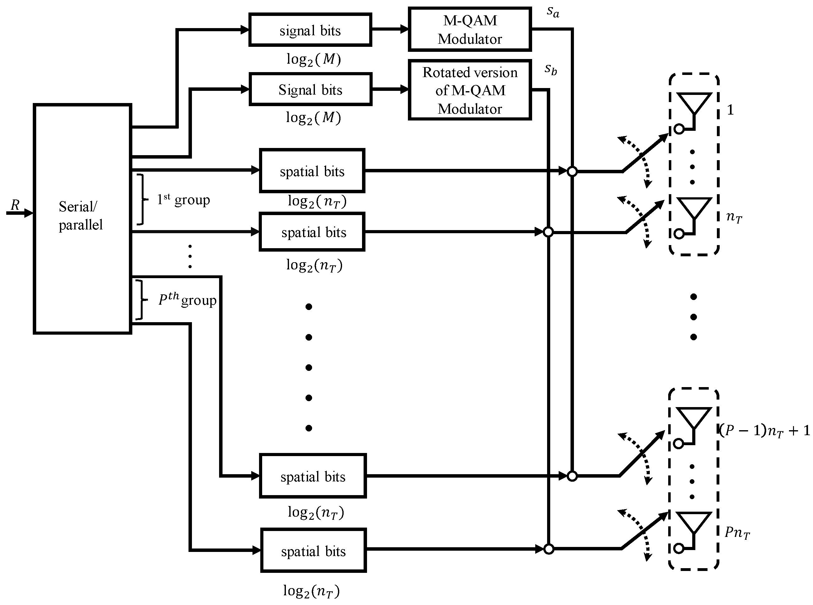
3. Parallel Complex Quadrature Spatial Modulation

In the PCQSM, the set of transmit antennas is divided into P equal-size subgroups and the system performs CQSM in each group, using the same two signal symbols, s a and s b . Each subgroup has n t = N t / P transmit antennas that are indexed independently. As such, the spectral efficiency of PCQSM is log 2 ( n T 2 P M 2 ) bits/s/Hz. A block representation of the PCQSM system model is given in Figure 1. At the receiver side, the received signal vector is expressed as follows,
y = 1 P i = 1 P h l i s a + i = 1 P h k i s b + n ,
where h l i ( h l 1 , h l 2 , , h l P ) and h k i ( h k 1 , h k 2 , , h k P ) represent the channel vectors that transmit s a and s b , respectively, in the i-th group. The antenna indices for the i-th group range from ( i 1 ) n T + 1 to i n T , such that 1 i P . Similar to the CQSM, s a and s b belong to distinct constellations of size M. The first constellation is a conventional QAM/PSK constellation and the second is a rotated version of the first. The results of the rotation angle optimization for the PCQSM are shown in Figure 2 for several system configurations with P = 2 and P = 4 . The angle that minimizes the the BER is considered as the optimal angle and is used in subsequent simulations for the given system configuration. Employing the maximum-likelihood (ML) detection at the receiver side, the estimated transmitted symbols and antenna indices are given by
l ^ , k ^ , s ^ a , s ^ b = arg min l , k , s a , s b y i = 1 P h l i s a i = 1 P h k i s b 2 = arg min l , k , s a , s b y g 2 = arg min l , k , s a , s b g 2 2 { y H g } ,
where
g = Δ i = 1 P h l i s a + i = 1 P h k i s b .
The sets l = { l 1 , l 2 , , l P } and k = { k 1 , k 2 , , k P } are the spatial indices from which s a and s b are transmitted in each group, respectively.
Example 1.
Assume a PCQSM system that achieves 12 bits/s/Hz with N t = 8 , N r = 4 , M = 4 , and P = 2 . Accordingly, the first and second group of the antenna set are { 1 , 2 , 3 , 4 } and { 5 , 6 , 7 , 8 } , respectively. Let the information stream at one channel use be [0 1 1 0 1 0 1 1 0 0 1 0], which is split into
m a = [ 0 1 ] , m b = [ 1 0 ] , p 1 = [ 1 0 1 1 ] , p 2 = [ 0 0 1 1 ] .
The first part m a modulates s a 2 = 1 + j from the QPSK constellation. The second part m b modulates s b 3 , where s b 3 = s a 3 e j θ o p t and s a 3 = 1 j . Using the same optimization method of [22], the optimal angle, obtained through extensive simulations, is θ o p t = 43 for the 8 × 4 PCQSM system. Therefore, s b 3 = 0.2767 j 1.3869 . Based on the p 1 part, the transmit antennas of index 3 and 4 in the first group are activated to transmit s a 2 and s b 3 , respectively. Similarly, the transmit antennas of index 5 and 8 in the second group are used to transmit the signal symbols. The signal symbols are normalized before transmission to achieve a unity transmission power. The received vector is then given by
y = 1 2 s a 2 ( h 3 + h 5 ) + s b 3 ( h 4 + h 8 ) + n .

4. Performance Analysis

Building upon the work in [26], let
x = 1 P i = 1 P h l i s a + h k i s b , x ^ = 1 P i = 1 P h l ^ i s ^ a + h k ^ i s ^ b .
be two noiseless received codewords. The pairwise error probability (PEP) is accordingly given by
P r x x ^ | H = Q x x ^ 2 2 σ n 2 = Q ζ ,
where
ζ = 1 2 σ n 2 x x ^ H x x ^ ,
and ζ is determined in the the same way as in [22], assuming P antenna subgroups. The average PEP assuming N r receive antennas is thereby determined as follows,
P ¯ e x x ^ = γ N r u = 1 N r 1 N r 1 + u u 1 γ u ,
where γ = 1 2 1 ζ / 2 1 + ζ / 2 . Averaging (13), the BER of the proposed scheme is upper-bounded by the average bit-error probability (ABEP), and this is given by
P b = 1 R 2 R i = 1 2 R u = 1 2 R P ¯ e x x ^ e i , u ,
where R denotes the total spectral efficiency of the system and e i , u is the number of bits that are erroneously detected in the error event P ¯ e x x ^ .

5. Computation Complexity of the Receiver

In addition to the performance analysis, the computation complexity of the ML receiver employed in PCQSM is analyzed and compared with that of PQSM and CQSM. The number of complex operations, specifically addition and multiplication operations, that are involved in the proposed PCQSM is determined from (7) and (8). To compute g in (8), 2 P N r multiplications and ( 2 P 1 ) N r additions are required and in (7), y g 2 requires N r additions and 2 N r 1 multiplications. The ML search is performed over the R-dimensional space. Therefore, the overall computation complexity of the ML receiver in PCQSM is given as
η P C Q S M = ( 4 P N r + 2 N r 1 ) 2 R .
The complexity of ML detector in PQSM, η P Q S M is provided in (Equation (26) in [18]). Assume that the spectral efficiency in PCQSM and PQSM are the same, the complexity ratio, η P C Q S M / η P Q S M = 1 . This implies that the two transmission scheme have the same complexity at the same transmission rate while PCQSM can significantly reduce the required number of transmit antennas.
Compared to CQSM, the difference in complexities is in the computation of g , which requires 2 N r multiplications and N r addition. Altogether, CQSM requires 6 N r 1 complex operations. Therefore, the ML receiver complexity ratio of PCQSM to CQSM is given as follows.
η P C Q S M η C Q S M = 4 P N r + 2 N r 1 6 N r 1 .
The expression in (16) is expected as PCQSM involves antenna groups and the implication is that the ML complexity grows as P increases. This slight increase in the computational complexity is tolerable, given the huge gains achieved by the PCQSM in terms of SNR and number of required transmit antennas.

6. Simulation Results

This section discusses the performance of the proposed scheme under different system configurations using Monte Carlo simulations. The obtained results are compared to the analytical results derived in Section 4. The channel is assumed to be frequency-flat Gaussian channel. The number of groups that are selected in all simulations for PCQSM is either P = 2 or 4.
First, we investigated the performance of the PCQSM in terms of the rotation angle. For N t = 8 , N r = 4 and a fixed SNR value of 28 dB, the BER versus the the rotation angle for six different system configurations is illustrated in Figure 2. Based on the depicted simulations, the angle that minimizes the BER is announced as the optimal rotation angle. For 8-QAM, the optimal rotation angle using P = 2 is either 21 or 69 as the graph is symmetrical. When PCQSM uses four groups, i.e., P = 4 , θ o p t is either 30 or 60 . For M = 16 , the optimal rotation angle is the same for both P = 2 and 4, with the value of θ o p t being either 26 or 64 . For M = 32 , θ o p t has a unique value of 45 . This implies that at low values of M, the optimal rotation angles are different. However, as the modulation order increases, θ o p t is the same for P = 2 and 4. The details of the optimal rotation angles obtained for all PCQSM configurations that are selected for evaluation in this section are presented in Table 1. It is important to note that the optimal rotation angles for CQSM are determined independently using extensive simulations. The optimal rotation angles of CQSM for two different system configurations are provided in Table 2.
As an example to validate the derived results, the analytical results of the performance of PCQSM using (14) is investigated for N t = 8 and N r = 4 , 6 , and 8 with modulation order of 8-QAM. This is illustrated in Figure 3a,b. Figure 3a depicts a comparison between the simulation and analytical results for PCQSM ( P = 2 ). Figure 3b illustrates the same for PCQSM ( P = 4 ). In all system configurations, the simulation results are upper bounded by the analytical results.
In Figure 4a, PCQSM is compared with the conventional SM schemes CQSM and QSM with the same modulation order and number of receive antennas, M = 4 and N r = 4 , respectively. While QSM and CQSM required 512 and 256 transmit antennas to achieve the transmission rate of 20 bit/s/Hz, PCQSM with P = 2 and P = 4 required 32 and 16 transmit antennas, respectively. The performances of the CQSM and PCQSM for P = 2 are similar, whereas PCQSM for P = 4 performed close to QSM. The 1 dB BER improvement in the performance of PCQSM with P = 2 as compared to PCQSM with P = 4 is due to the reduced number of antennas per subgroup. As the number of antennas reduces, the probability of transmitting the two signal symbols s a and s b from the same antennas increases. This leads to a slight degradation in error performance. This degradation is tolerable given the huge gains in the terms of the number of required antennas for high p values.
To provide a fair comparison between the performances of PQSM and PCQSM, the same number of antenna groups is selected. The number of transmit antennas required in the two schemes is the same. However, to achieve the same spectral efficiency, PQSM requires higher modulation orders. Figure 4b depicts the error performance of the two systems for two configurations. While PQSM requires 16-QAM modulation to achieve a spectral efficiency of 20 bit/s/Hz, PCQSM on the contrary requires 4-QAM. As a result, the PCQSM outperforms PQSM by approximately 4 dB in both groups at a target BER of 10 4 .
Finally, PCQSM is compared with the three conventional SM schemes to achieve the same spectral efficiency of 24 bit/s/Hz, using the same modulation order of M = 16 . QSM requires 1024 transmit antennas, CQSM requires 256, PQSM ( P = 2 ) requires 64, and PCQSM ( P = 2 ) requires 32, the least number of transmit antenna, to achieve the same spectral efficiency of 24 bit/s/Hz. Figure 5 illustrates the BER performance of these transmission schemes. At a BER of 10 4 , PCQSM ( P = 2 ) attained negligible BER difference when compared to that of CQSM, and about 1 dB improvement as compared to QSM and PQSM ( P = 2 ).

7. Conclusions

In this paper, we proposed the PCQSM MIMO technique to achieve a high spectral efficiency and reduction in the number of required transmit antennas of the conventional SM techniques. To achieve these advantages, the proposed PCQSM splits the available set of transmit antennas into subgroups of equal size. Two signal symbols are modulated and encoded using the conventional CQSM in each of the subgroups. By doing so, the proposed technique requires a small fraction of the number of transmitted antennas needed by the conventional systems to achieve a certain spectral efficiency. This is achieved without any sacrifice in the error performance or increase in the hardware requirements, as compared to CQSM. We provided the analytical performance of the proposed technique and validate it via simulation results. The simulation results show that the proposed PCQSM performs close to several conventional techniques and outperforms others, while maintaining low hardware requirements and number of required transmit antennas.

Author Contributions

Conceptualization, S.M., M.M., and K.-S.C.; methodology, S.M., T.H., N.M., M.M., and K.-S.C.; software, S.M., T.H., and N.M.; validation, S.M., T.H., N.M., M.M., and K.-S.C.; formal analysis, M.M. and S.M.; investigation, S.M., T.H., N.M., M.M., and K.-S.C.; resources, K.-S.C. and M.M.; data curation, S.M., T.H., and N.M.; writing—original draft preparation, S.M., M.M., and K.-S.C.; writing—review and editing, S.M., T.H., N.M., M.M., and K.-S.C.; visualization, S.M., T.H., and N.M.; supervision, K.-S.C. and M.M.; project administration, M.M.; funding acquisition, K.-S.C. All authors have read and agreed to the published version of the manuscript.

Funding

This work was supported by the BK21 plus program through the National Research Foundation (NRF) funded by the Ministry of Education of Korea.

Institutional Review Board Statement

Not applicable.

Informed Consent Statement

Not applicable.

Data Availability Statement

Not applicable.

Conflicts of Interest

The authors declare no conflict of interest.

Abbreviations

The following abbreviations are used in this manuscript:
ABEPAverage bit error probability
BERBit error rate
CQSMComplex quadrature spatial modulation
IQSMImproved quadrature spatial modulation
IMIndex modulation
MA-SMMultiple active spatial modulation
MIMOMultiple-input multiple-output
MLMaximum likelihood
PCQSMParallel complex quadrature spatial modulation
PQSMParallel quadrature spatial modulation
PSMParallel spatial modulation
PEPPairwise-error probability
PSKPhase shift keying
QAMQuadrature amplitude modulation
QSMQuadrature spatial modulation
RFRadio frequency
SMSpatial modulation
SNRSignal to noise ratio

References

  1. Agiwal, M.; Roy, A.; Saxena, N. Next Generation 5G Wireless Networks: A Comprehensive Survey. IEEE Commun. Surv. Tutor. 2016, 18, 1617–1655. [Google Scholar] [CrossRef]
  2. Basar, E.; Wen, M.; Mesleh, R.; Renzo, M.D.; Xiao, Y.; Haas, H. Index Modulation Techniques for Next-Generation Wireless Networks. IEEE Access 2017, 5, 16693–16746. [Google Scholar] [CrossRef]
  3. Mesleh, R.Y.; Haas, H.; Sinanovic, S.; Ahn, C.W.; Yun, S. Spatial Modulation. IEEE Trans. Veh. Technol. 2008, 57, 2228–2241. [Google Scholar] [CrossRef]
  4. Kaddoum, G.; Ahmed, M.; Nijsure, Y. Code index modulation: A high data rate and energy efficient communication system. IEEE Commun. Lett. 2015, 19, 75–178. [Google Scholar] [CrossRef]
  5. Zhang, J.; Wang, Y.; Zhang, J.; Ding, L. Polarization shift keying (PolarSK): System scheme and performance analysis. IEEE Trans. Veh. Technol. 2017, 66, 10139–10155. [Google Scholar] [CrossRef]
  6. Basar, E.g.; Aygolu, U.; Panayirci, E.; Poor, H.V. Orthogonal frequency division multiplexing with index modulation. IEEE Trans. Signal Proc. 2013, 61, 5536–5549. [Google Scholar] [CrossRef]
  7. Zhu, X.; Wang, Z.; Wang, Q.; Haas, H. Virtual spatial modulation for MIMO systems. In Proceedings of the 2016 IEEE Global Communications Conference (GLOBECOM), Washington, DC, USA, 4–8 December 2016. [Google Scholar]
  8. Li, J.; Wen, M.; Zhang, M.; Cheng, X. Virtual spatial modulation. IEEE Access 2016, 4, 6929–6938. [Google Scholar] [CrossRef]
  9. Wen, M.; Zheng, B.; Kim, K.J.; Di Renzo, M.; Tsiftsis, T.A.; Chen, K.C.; Al-Dhahir, N. A Survey on Spatial Modulation in Emerging Wireless Systems: Research Progresses and Applications. IEEE J. Select. Areas Commun. 2019, 37, 1949–1972. [Google Scholar] [CrossRef] [Green Version]
  10. Younis, A.; Serafimovski, N.; Mesleh, R.; Haas, H. Generalised spatial modulation. In Proceedings of the 2010 Conference Record of the Forty Fourth Asilomar Conference on Signals, Systems and Computers, Pacific Grove, CA, USA, 7–10 November 2010; pp. 1498–1502. [Google Scholar]
  11. Wang, J.; Jia, S.; Song, J. Generalised spatial modulation with multiple active transmit antennas and low complexity detection scheme. IEEE Trans. Wirel. Commun. 2012, 11, 1605–1615. [Google Scholar] [CrossRef]
  12. Ju, P.; Zhang, M.; Cheng, X.; Wang, C.X.; Yang, L. Generalized spatial modulation with transmit antenna grouping for correlated channels. In Proceedings of the 2016 IEEE International Conference on Communications (ICC), Kuala Lumpur, Malaysia, 22–27 May 2016; pp. 1–6. [Google Scholar]
  13. AbuTayeh, S.; Alsalahat, M.; Kaddumi, I.; Alqannas, Y.; Althunibat, S.; Mesleh, R. A half-full transmit-diversity spatial modulation scheme. In Proceedings of the International Conference on Broadband Communications, Networks and Systems (Portugal, 2018) (BROADNETS), Faro, Portugal, 19–20 September 2018; pp. 257–266. [Google Scholar]
  14. Qu, W.; Zhang, M.; Cheng, X.; Ju, P. Generalized Spatial Modulation With Transmit Antenna Grouping for Massive MIMO. IEEE Access 2017, 5, 26798–26807. [Google Scholar] [CrossRef]
  15. Xiao, L.; Xiao, Y.; Xu, C.; Lei, X.; Yang, P.; Li, S.; Hanzo, L. Compressed-sensing assisted spatial multiplexing aided spatial modulation. IEEE Trans. Wirel. Commun. 2018, 17, 794–807. [Google Scholar] [CrossRef]
  16. Mohaisen, M. Constellation design and performance analysis of the parallel spatial modulation. Int. J. Commun. Syst. 2019, 32, e4165. [Google Scholar] [CrossRef]
  17. Mesleh, R.; Ikki, S.S.; Aggoune, H.M. Quadrature Spatial Modulation. IEEE Trans. Veh. Technol. 2015, 64, 2738–2742. [Google Scholar] [CrossRef]
  18. Huang, G.; Li, C.; Aissa, S.; Xia, M. Parallel Quadrature Spatial Modulation for Massive MIMO Systems With ICI Avoidance. IEEE Access 2019, 7, 154750–154760. [Google Scholar] [CrossRef]
  19. Castillo-Soria, F.R.; Cortez-González, J.; Ramirez-Gutierrez, R.; Maciel-Barboza, F.M.; Soriano-Equigua, L. Generalized quadrature spatial modulation scheme using antenna grouping. ETRI J. 2017, 39, 707–717. [Google Scholar] [CrossRef]
  20. Vo, B.; Nguyen, H.H. Improved Quadrature Spatial Modulation. In Proceedings of the 2017 IEEE 86th Vehicular Technology Conference (VTC-Fall), Toronto, ON, Canada, 24–27 September 2017; pp. 1–5. [Google Scholar]
  21. Holoubi, T.; Murtala, S.; Muchena, N.; Mohaisen, M. On the performance of improved quadrature spatial modulation. ETRI J. 2020, 42, 562–574. [Google Scholar] [CrossRef]
  22. Mohaisen, M.; Lee, S. Complex Quadrature Spatial Modulation. ETRI J. 2017, 39, 514–524. [Google Scholar] [CrossRef]
  23. Mohaisen, M. Increasing the minimum Euclidean distance of the complex quadrature spatial modulation. IET Commun. 2018, 12, 854–860. [Google Scholar] [CrossRef]
  24. Iqbal, A.; Mohaisen, M.; Kwak, K.S. Modulation Set Optimization for the Improved Complex Quadrature SM. Wirel. Commun. Mobile Comput. 2018, 2018, 6769484. [Google Scholar] [CrossRef]
  25. Mohaisen, M. Generalized complex quadrature spatial modulation. Wirel. Commun. Mob. Comput. 2019, 2019, 3137927. [Google Scholar] [CrossRef] [Green Version]
  26. Gritsch, G.; Weinrichter, H.; Rupp, M. A union bound of the bit error ratio for data transmission over correlated wireless MIMO channels. In Proceedings of the 2004 IEEE International Conference on Acoustics, Speech, and Signal Processing, Montreal, QC, Canada, 17–21 May 2004; Volume 4, pp. iv-405–iv-408. [Google Scholar]
Figure 1. A block representation of parallel complex quadrature spatial modulation (PCQSM) with P antenna groups.
Applsci 11 00330 g001
Figure 2. Optimized rotation angle for PCQSM with N t = 8 , N r = 4 .
Applsci 11 00330 g002
Figure 3. Theoretical performance of PCQSM in comparison with PCQSM simulation for (a) P = 2 and (b) P = 4 at a transmission rate of 14 bits/s/Hz with 8-QAM, N t = 8 and N r = 4 , 6 , and 8, respectively.
Applsci 11 00330 g003
Figure 4. Performance comparison of (a) SM schemes with transmission rate of 20 bits/s/Hz with same number of receive antenna, N r = 4 and modulation order M = 4 -QAM. (b) PQSM and PCQSM schemes with 2 and 4 groups to achieve a transmission rate of 20 bits/s/Hz, N r = 4 .
Applsci 11 00330 g004
Figure 5. Performance comparison of SM schemes with transmission rate of 24 bits/s/Hz with N r = 4 and modulation order, M = 16 -QAM.
Applsci 11 00330 g005
Table 1. Optimal rotation angle, θ o p t , for several PCQSM system configurations.
( N t ; N r ; P; M) θ opt ( ) ( N t , N r , P, M) θ opt ( )
(8, 4, 2, 8) (8, 4, 4, 8)
(8, 6, 2, 8)21/69(8, 6, 4, 8)30/60
(8, 8, 2, 8) (8, 8, 4, 8)
(8, 4, 2, 16)26/64(8, 4, 2, 32)45
(8, 4, 4, 16) (8, 4, 4, 32)
(32, 4, 2, 4)36/27/41(16, 4, 4, 4)31/41
(32, 4, 2, 16)12/21/43
Table 2. Optimal rotation angle, θ o p t , for CQSM system configurations.
( N t , N r , M) θ opt ( )
(256, 4, 4)36
(256, 4, 16)44
Publisher’s Note: MDPI stays neutral with regard to jurisdictional claims in published maps and institutional affiliations.

