Article

Design and Numerical Simulation-Based Optimization of a Novel Flat-Face Coupling System for Hydraulic Power Equipment

1
School of Mechanical and Aerospace Engineering, Gyeongsang National University, 501 Jinju-daero, Jinju-si, Gyeongsangnam-do 52828, Korea
2
School of Integrated Technology, Gwangju Institute of Science and Technology, 123 Cheomdangwagi-ro, Buk-gu, Gwangju 61005, Korea
*
Authors to whom correspondence should be addressed.
Author Contributions: Y.T. Wu and Z. Qin contributed equally to this work.
Appl. Sci. 2021, 11(1), 388; https://doi.org/10.3390/app11010388
Submission received: 15 December 2020 / Revised: 27 December 2020 / Accepted: 29 December 2020 / Published: 3 January 2021

Abstract

:
Coupling systems play a vital role in hydraulic power transmission equipment. In recent years, flat-face coupling systems have been extensively studied due to their environment friendly features. The difficulty of the connection process of hydraulic equipment increases with the increase in their working pressure. To improve the convenience of making high-pressure connections, a novel flat-face coupling system is proposed in this article. In the proposed design, which is based on the conventional flat-face coupling system, the resistance caused by high hydraulic fluid pressure during coupling is drastically reduced by the addition of an instantaneous pressure relief module. In this study, the theoretical model of the system kinetics is established to illustrate the operational mechanism of the novel design, and a series of computational fluid dynamics numerical investigations based on the novel dynamic mesh technology and Ansys Mosaic meshing technology are implemented to verify the rationality of the proposed design. Additionally, an optimal design of the novel flat-face coupling system is proposed to reduce the energy loss during hydraulic power transmission.

1. Introduction

Hydraulic power transmission technology has seen continuous development since the construction of the first hydraulic press in 1795. Due to their reliability, high precision, rapid response and large driving force, hydraulic equipment are widely used in aerospace, automobiles, agricultural machinery, the petroleum industry, military machinery, manufacturing and other fields [1,2,3,4,5,6,7].
Due to the work requirements of hydraulic power systems, the existence of hydraulic oil pollution, leakage, corrosion and other hidden dangers is inevitable [8]. Therefore, numerous scholars have sought to improve the work performance, safety, environmental protection, etc. of hydraulic systems. Sakaino et al. [9] proposed a novel electro-hydrostatic actuator (EHA) design to monitor the oil leakage and static friction, and empirically verified their proposed model. Rinneberg et al. [10] proposed an accessorial identification system for intelligent equipment based on the passive radio frequency sensing technology. This research provides a reliable alternative for equipment operators. Wang et al. [11] proposed a new quick coupling system with a “points to points” mechanism. This design improves the reliability of the quick coupling system under blind operation.
In the hydraulic power system, the hydraulic energy is transmitted and controlled by the pressure difference of the fluid. Hydraulic quick couplings are an essential element in hydraulic power systems as they can connect or disconnect the high-pressure hydraulic circuits flexibly and quickly without the need for extra tools or special equipment [12]. In these couplings, the energy losses occur mainly in the valves, coupling gaps and the gaps of the working mechanism of positive displacement machines such as pumps and motors. Śliwiński proposed a new design for satellite pumps and investigated their volumetric and hydraulic-mechanical losses, their efficiencies and their noise characteristics [13]. Śliwiński also established a theoretical energy loss model for a hydraulic motor composed of planetary gears and verified it through experiments [14]. Taking inspiration from these works, this article presents a series of numerical investigations on the energy losses occurring in the proposed novel hydraulic coupling system.
According to the shape of the connector, hydraulic quick couplings can be divided into three main categories: (1) poppet type, (2) spherical type and (3) flat-face type [15,16,17]. Compared to poppet type and spherical type couplings, flat-face type is a recent development that can minimize the leakage of hydraulic fluid during connection and disconnection to reduce the environmental pollution. However, the complicated geometry of the flat-face connection system leads to a higher energy consumption during hydraulic transmission. Therefore, a number of studies proposing different optimization schemes have been carried out to reduce this pressure loss problem, [18,19,20,21,22].
The working pressure of hydraulic power systems has increased with the development of industry [23]. This increase in the working pressure of the system also increases the difficulty of the coupling process of hydraulic circuits. A variety of methods have been proposed to improve the convenience of the coupling process under high operating pressures [24,25]. However, it has been difficult to greatly improve the conventional flat-face coupling system (CFFCS) due to the size limitations of hydraulic circuits.
In this research, a novel flat-face coupling system (NFFCS) design with an instantaneous pressure relief based on Pascal’s law is proposed, and validated through a series of comparative numerical investigations of 10 mm CFFCS and NFFCS. The instantaneous pressure relief effect of the proposed NFFCS design is verified through transient simulation results based on the novel dynamic mesh analysis method. In order to reduce the energy loss during hydraulic power transmission, the optimization of the hydraulic flow characteristics of NFFCS is implemented based on Ansys Mosaic meshing technology and CFD simulation technology. Finally, the optimal geometric design is determined through the comparison of the investigation results. The optimized novel flat-face coupling system proposed in this paper consumes less installation thrust, and has a smaller energy consumption than the currently widely used CFFCS design. This research provides a valuable technical reference for the design of quick coupling systems that are better able to deal with the increasing operating pressures of hydraulic power transmission systems used in modern industry. The flat-face technology can better prevent oil leakages, making it more suited to the requirements of green technology.

2. Mechanism Design and Kinetics

There are many types of quick connector for hydraulic power transmission systems. The traditional poppet type and spherical type quick connectors make the hydraulic oil converge in the gap between the valve core and the coupling glove due to their irregular geometry and uneven contact surfaces. During the disconnection process of such coupling systems, this hydraulic oil flows out into the environment and causes pollution. In order to overcome this problem, environmentally friendly flat-face type coupling systems have been proposed, which have been widely used and recognized. In recent years, with the increase of operating pressures in hydraulic power transmission systems, the connecting characteristics of CFFCS are no longer sufficient to meet the requirements due to high coupling resistance. In order to make the coupling process more convenient, a NFFCS with an instantaneous pressure relief function is proposed in this research. The design of the NFFCS and its comparison with the CFFCS are presented below.
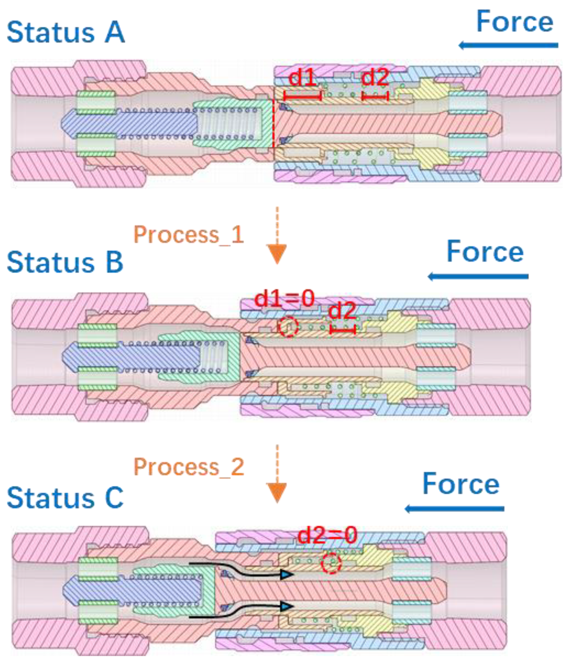
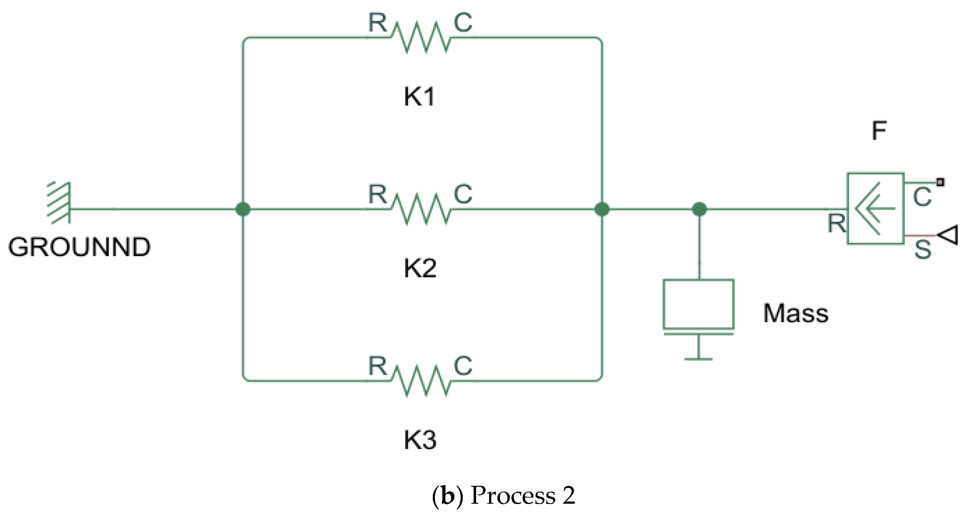
Figure 1 shows the mechanism design of the CFFCS in the separated state. The plug connector on the left side and the socket connector on the right side of Figure 1 both have one-way self-sealing valves (1 and 4) that ensure the blockage of hydraulic fluid in the disconnected state. During the connection process, the pressure of the sealed high-pressure hydraulic fluid acts on the one-way self-sealing valve to generate a high amount of force (coupling resistance) that must be overcome to complete the connection process. Figure 2 shows the kinematics of the connection process of the plug and socket connectors of the CFFCS. Status A is the state where the plug and the socket have just made contact. During the course of pushing the socket to the left while the plug is fixed, Process 1 and Process 2 take place. Upon completion of these processes, the fluid path is fully opened. In order to facilitate their understanding, the theoretical models of the two processes are established, as shown in Figure 3, where only the influence of the mechanical spring element on the thrust is considered.
It can be seen that during process 1, in order to move to the left, the pin (5) in the socket that is rigidly connected to the shell of the entire socket pushes the valve (1) of the plug to overcome the elastic resistance of the spring K2. At the same time, due to the reaction force given by the glove (2) in the plug, the glove (3) in the socket moves to the right against the elastic force of the spring K1. The theoretical mechanical model of this process is shown in Figure 3a.
d1 represents the distance between the glove (3) and valve (4) in the socket. When d1 reduces to zero, the entire system reaches status B. As shown in Figure 3b, during Process 2, the valve (4) in the socket moves to the right along the guide (6). During this process, the springs K1, K2, and K3 work simultaneously. When valve (4) starts to move, the hydraulic fluid starts to flow through the entire coupling system. Finally, the fluid path is fully opened when the valve (4) makes contact with the guide (6) (i.e., d2 = 0).
It can be seen that in the connection process of the CFFCS, in addition to overcoming the resistance of the spring, it is also necessary to overcome the resistance due to the pressure of the hydraulic fluid acting on the single self-sealing valve (1).
In actual operation, the resistance due to fluid pressure is usually very large and requires the use of additional tools to assist in establishing the connection. Therefore, the CFFCS cannot meet the requirements for easy quick coupling under higher-pressure conditions. To solve this problem, we propose the NFFCS design that is presented below.
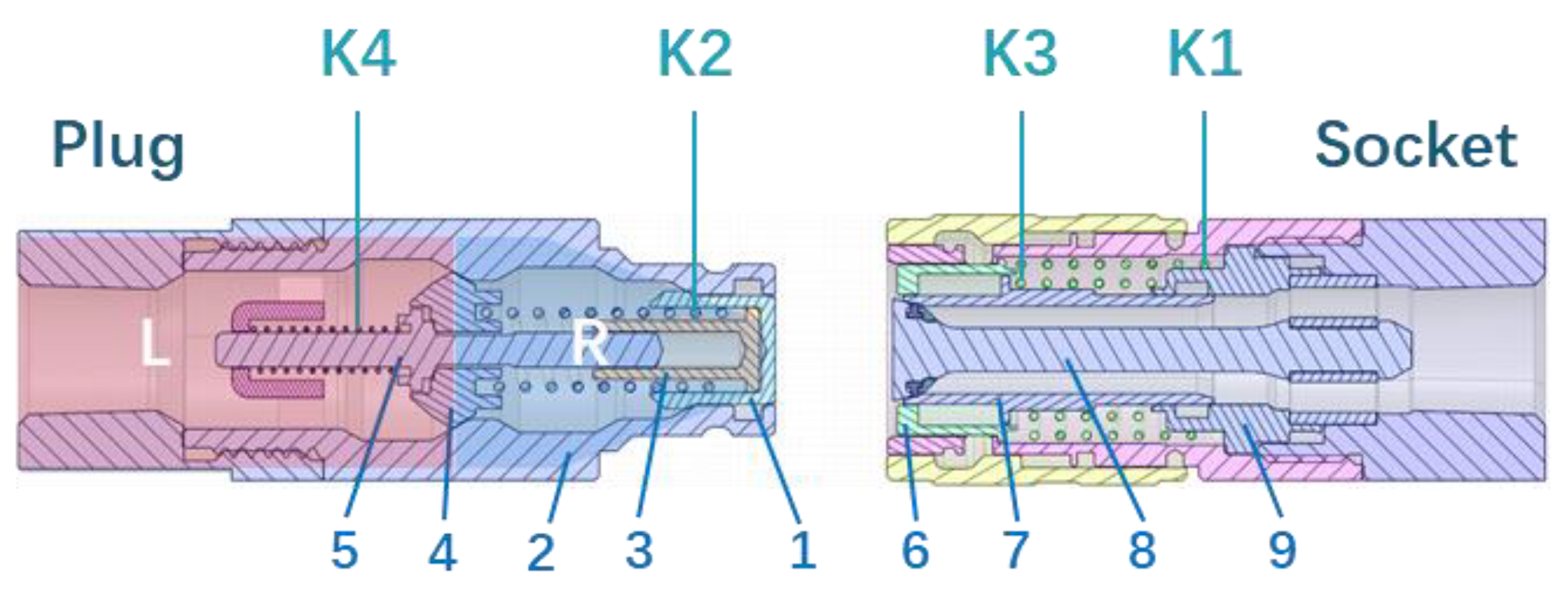
Figure 4 shows the internal mechanism of the NFFCS. Compared to the CFFCS, the main difference lies in the design of the plug connector. Valve (4) and pin valve (5) divide the plug into the L and R chambers, where the high pressure hydraulic oil is completely sealed in the L chamber due to the pressure acting on the valves. The valve (1) in chamber R has no fluid pressure acting on it, which means that opening this valve (1) requires us to overcome only the spring resistance.
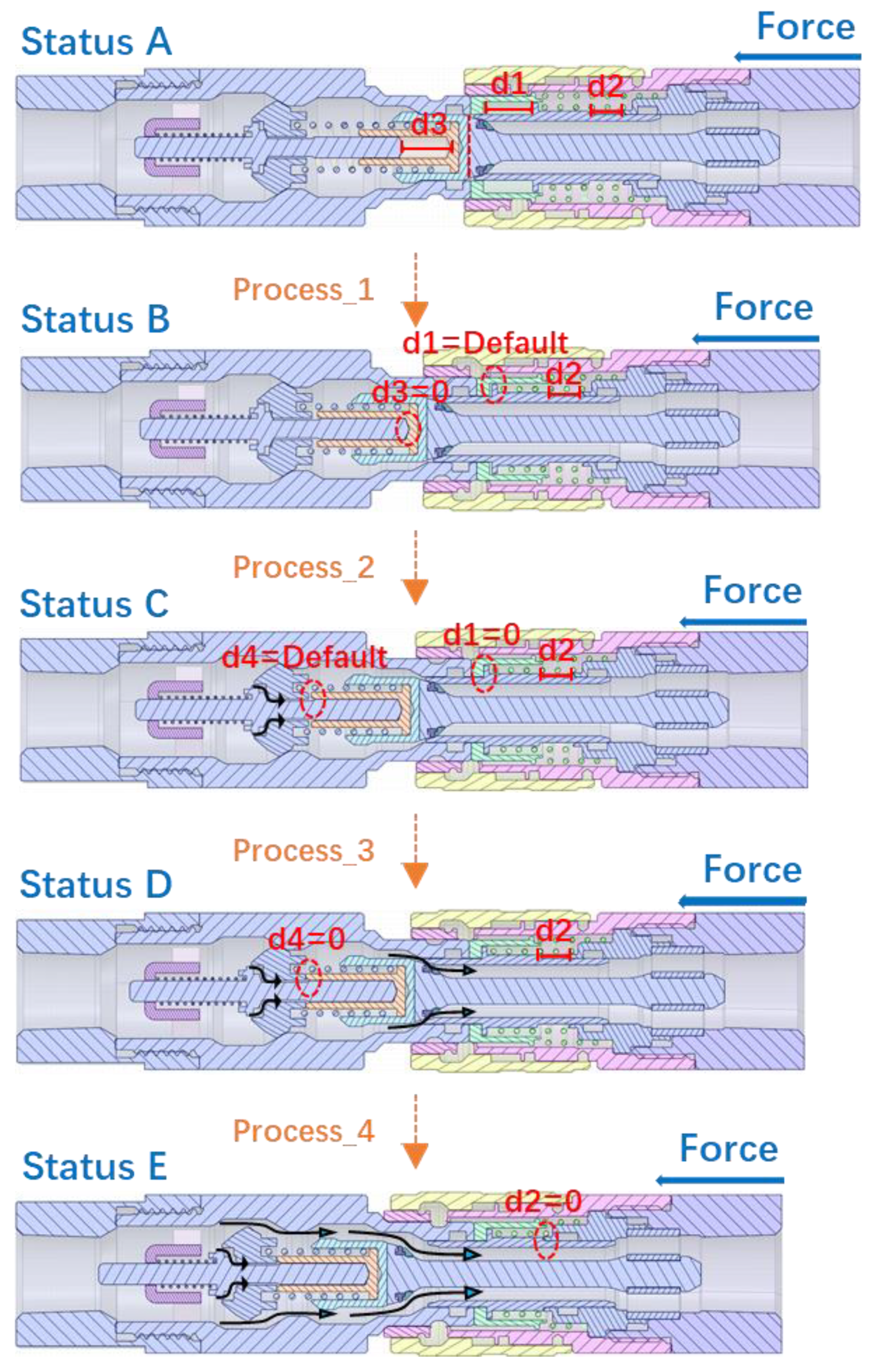
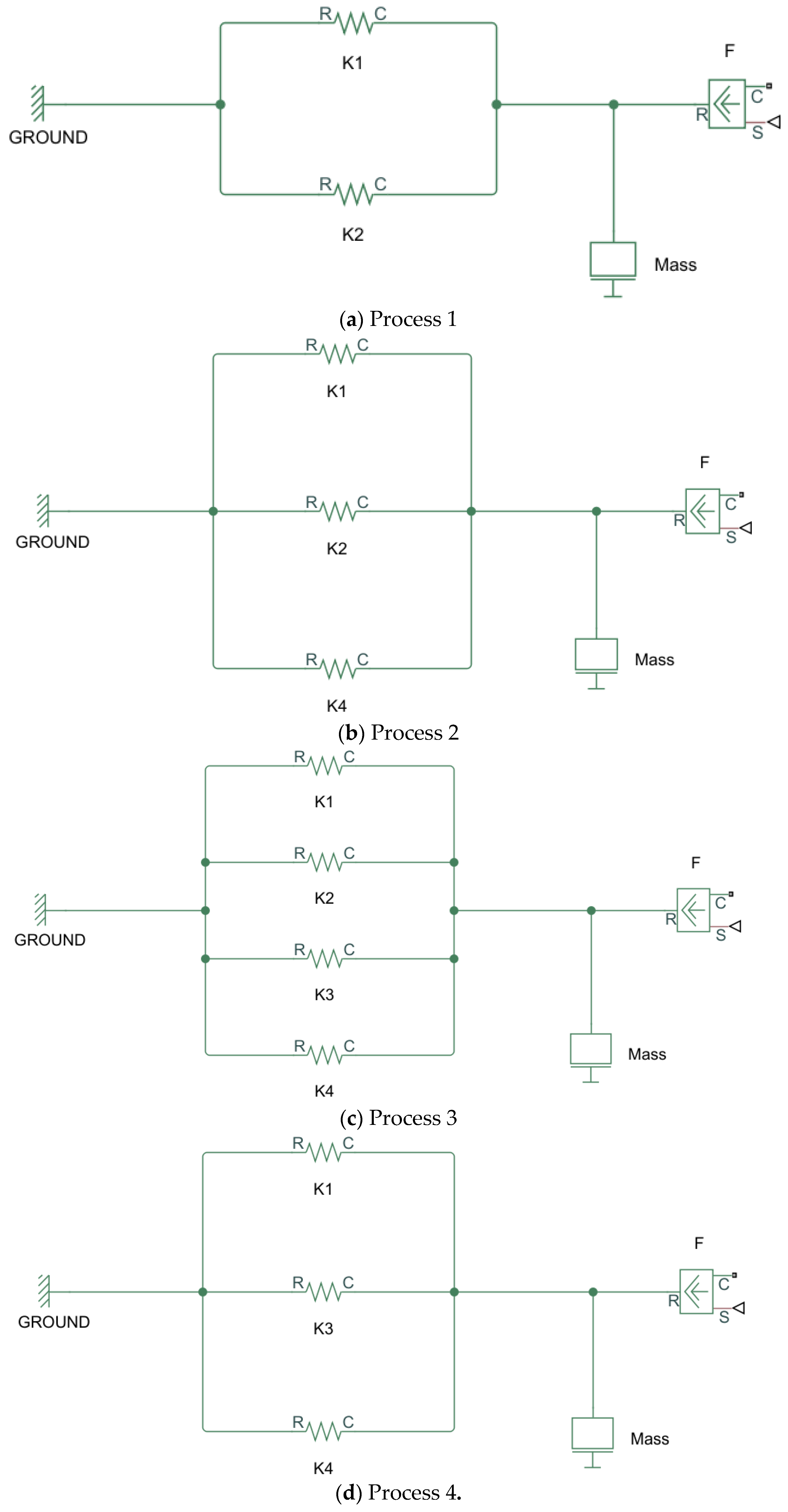
Figure 5 shows the kinematics of the coupling process of the plug and socket connectors. The state of the plug and socket connectors just as they make contact is shown as status A. Then, the socket connector is pushed to the left until it is fully connected. According to the movement of the mechanism, the whole operation can be divided into four processes. For the convenience of observation, the theoretical models for these four processes are established (similar to the CFFCS, i.e., only considering the effect of the mechanical elements) as shown in Figure 6.
In a similar way to the CFFCS, during Process 1, the pin (8) in the socket moves to the left and pushes the valve (1) in the plug to overcome the elastic resistance of spring K2. At the same time, the glove (2) in the plug moves to the right and pushes the glove (6) in the socket to overcome the elastic resistance of K1. The theoretical model of this process is shown in Figure 6a. d3 represents the distance between the pin sleeve (3) and the pin valve (5). Under the action of thrust, d3 gradually decreases to zero, at which point the entire system reaches status B. Then, during Process 2 (shown in Figure 6b), the pin valve (5) begins to overcome the resistance of spring K4 and starts to move to the left due to the thrust. As shown in status C, a gap A is generated between pin valve (5) and valve (4), connecting the L and R chambers. It is worth mentioning that, unlike the valve of the CFFCS, the newly designed pin valve (5) has a small cross-sectional area and, therefore, according to Pascal’s law, experiences a very small force due to the hydraulic fluid pressure. Thus, the resistance from high-pressure hydraulic fluid that needs to be overcome during process 2 is very small and the pressure relief effect can be achieved with a small thrust force. d1 represents the distance between the glove (6) and valve (7) position blocks in the socket. With further pushing to the left, when d1 becomes equal to zero, the entire system reaches status C. During Process 3 (shown in Figure 6c), springs K1, K2, K3, and K4 work simultaneously. The movement of valve (7) means that the hydraulic fluid now begins to flow through the entire coupling system. d4 represents the distance between valve (4) and pin sleeve (3). When d4 becomes equal to zero, the entire system reaches status D. It is worth noting here that although Process 2 and Process 3 occur in a set order, Process 3 is extremely short and can be ignored. Thus, the system quickly transits to the next process, i.e., Process 4. That is to say that the opening of pin valve (5) during Process 2 does not exert any pressure on the opening of valve (1). This feature has been designed to prevent the overflow of hydraulic fluid when the coupling system is not fully connected. As shown in Figure 6d, during Process 4, the valve (4) in the plug is pushed to the left. Since at this point the pin valve (5) is open, the pressure difference between the L and R chambers is almost zero, which means that the pressure acting on the left side of the valve (4) disappears so it (valve (4)) can be easily pushed away. During this process, springs K1, K3, and K4 continue to work together. When valve (7) and guide (9) make contact (i.e., d2 = 0), it means that the circuit is fully connected and the coupling process is complete.
To sum up, during the connection process of the NFFCS, due to the pin valve (5) of the instantaneous pressure relief device, at first, only some of the high-pressure hydraulic fluid is introduced into the socket to achieve the effect of pressure relief, and then the entire hydraulic circuit is opened, which greatly reduces the resistance due to pressure that needs to be overcome to achieve successful coupling. In this chapter, we have only qualitatively analyzed the pressure that we need to overcome during the coupling process. In the following section, numerical simulations are used to quantitatively observe and analyze the magnitude of the pressure that needs to be overcome in this process.

3. Valve Opening Characteristics

3.1. Investigation Methods and Boundary Conditions

The opening and closing of the valve is typically an almost instantaneous process. In actual operation, it is difficult to observe the change of the internal flow field during the opening of the high-pressure valve. With the development of information technology, various simulation tools based on numerical investigation methods are being widely used in various industries to overcome the deficiencies of experimental methods [26,27,28,29,30,31]. For valve design problems, computational fluid dynamics (CFD)-based simulation methods are often used in the industry to study the dynamic changes in the flow field [32,33,34].
In this numerical investigation, the global unstructured tetrahedral mesh is used for the discretization of the high-pressure liquid basin, and the grid at the valve gap is locally refined. The Reynolds-averaged Navier–Stokes (RANS) equation governing the fluid flow is solved in the commercial CFD software Ansys Fluent using a workstation (Manufacturer: Lenovo, Seoul, Korea) with an Intel Xeon E5 2690 v4 processer operating at 2.6 GHz with 128 GB of RAM. In the simulation, the fluid is assumed to be incompressible and conforming to the RANS equation. Ansys fluent provides many RANS turbulence models to solve different fluid dynamics problems (e.g., Spalart–Allmaras, Standard k-epsilon, renormalization group (RNG) k-epsilon, Realizable k-epsilon, standard k-omega, Menter’s shear stress transport (SST) k-omega, Reynolds stress etc.) [35]. In this study, the Standard k-epsilon model was adopted because it has been verified by numerous studies that, for calculations related to hydraulic power transmission systems, this model is more stable, economical and accurate than other turbulence models [32,34]. The semi-Implicit method for pressure implicit method for pressure-linked equations (SIMPLE) solver is used to solve momentum and continuous equations. This method uses a second-order upwind style to discretize the equations in parallel grid nodes to ensure the accuracy of the simulation results. The boundary conditions are set as pressure inlet and pressure outlet for this calculation domain. The initial pressure value of the valve is set as 630 kPa, and the outlet pressure is set as 530 kPa. In this simulation, international organization for standardization (ISO) VG32 hydraulic oil with a density of 844.4 kg/m3 and a dynamic viscosity of 0.0135 kg/m·s is used as the transportation medium.
In order to more intuitively observe the NFFCS’ effects of instantaneous pressure relief and easy coupling, same-sized (ISO 16082 size 10) CFFCS and NFFCS were separately pre-processed for modeling and simulation. In this study, the entire valve opening process of the two hydraulic couplings was simulated using novel dynamic mesh technology. The dynamic mesh algorithms mainly include layering, smoothing and remeshing [22]. Considering the complexity of the internal geometric structure of the hydraulic coupling systems, it is difficult to use a layering method that is highly dependent on prismatic meshes. Therefore, in this study, smoothing and remeshing methods were adopted for dynamic meshing.
The general conservation equation of a dynamic mesh [36,37] for a general scalar (Φ) on an arbitrary control volume (V), whose boundary is moving, can be written as:
t V ρ d V + A ρ ( v v g ) · d A = A ( Γ ) · d A + V S d V
where v is the speed vector; v g ts the grid velocity of the moving mesh, ρ is the liquid density, Γ is the diffusion coefficient, and S represents the source term of .
In CFD simulations, although the “convergence” based on RMS error values, monitoring points and imbalances can ensure the accuracy of the simulation results to a certain extent, the grid-independent inspection of each model is necessary to minimize the effect of different grid resolutions on the simulation outcomes [38]. Therefore, in the simulation of the opening characteristics of the CFFCS, we used different numbers of grids of the fluid domain (4.3 × 10⁶ (coarse), 5.8 × 10⁶ (medium) and 6.6 × 10⁶ (fine)). Considering the complexity of the internal geometry of the coupling system and the computability of the dynamic mesh simulation, it is difficult to refine the boundary layer separately. Therefore, in this study, a method based on the global size control of unstructured grids is used to ensure the correctness of the calculation results of viscous flow near the wall. The special control method for moving zones in dynamic mesh simulation is described in detail in the following text. The average skewness of the grid was limited to less than 0.5. Then, through comparison of the required thrust during the opening process of the CFFCS under the three grid models (coarse, medium and fine), it was found that the maximum deviation of the coarse model was 5.62% relative to the fine model, while the maximum deviation of the medium model was only 1.72%. Thus, considering both the economics of the calculation and the accuracy of the simulation, the medium model was selected for further simulations carried out in this research. The same grid independence check strategy was also adopted for all the other simulation models mentioned in this article.
Figure 7a,b respectively show the meshed cross-sections of the CFFCS and NFFCS, that were obtained after the grid independence verification. According to the rules of the dynamic meshing method, the volume of the grid cannot be zero. Therefore, a gap must be left between the valve and the glove during modeling. In order to simulate the true opening process to the greatest extent, this gap between the valve and the glove must be very small. Thus, the initial gap in this study is defined as 0.2 mm.
For the CFFCS, the wall contacting the valve is set as a moving rigid body, and its velocity is defined by the profile programming. In the NFFCS, the instantaneous pressure relief pin valve will be opened before the larger valve is opened. For this process, the velocity at the flow area of the pin valve and the larger valve were defined separately. The total coupling duration of the two valves is set as 2.0 s.

3.2. Results and Discussion

Figure 8 shows the pressure and velocity distribution contours at three instances during the valve opening process of the CFFCS: (a) the beginning of coupling (t = 0.5 s, the valve is not opened); (b) the moment the valve has just started opening (t = 1 s); (c) the valve is fully opened (t = 2 s). It can be seen from Figure 8a that the two chambers are not connected and the pressure is evenly distributed in the high-pressure chamber on the left side of the valve and in the low-pressure area on the right. At this time, the flow velocity in the two chambers is almost zero. Since at least one layer of mesh is required in the dynamic mesh setting, it is inevitable that a large flow velocity will be generated in the gap in the simulation results. In the actual opening process, due to the presence of the seal, such a large flow velocity does not exist in the gap. This study only observes the characteristics of the flow in the fluid domain during the coupling process, thus the influence of such unavoidable limitations of the simulation methodology on the research results is ignored.
The left and right chambers start to connect during the leftward movement of the valve (as shown in Figure 8b). At this time, the gap between the valve and glove reaches its smallest value. In this state, the fluid is pushed by the high pressure in the left chamber to pass through the gap at a great velocity and form an obvious velocity gradient in the low-pressure area. At this time, the pressure distribution of the two chambers still does not change greatly.
At t = 2.0 s, CFFCS completes the coupling process, and the entire hydraulic circuit is fully connected (as shown in Figure 8c). In this state, the pressure distribution in the entire watershed tends to be uniform, the inlet maintains a high pressure, and there is a high and even pressure gradient. The overall flow velocity distribution corresponds to the pressure distribution.
Figure 9 shows the pressure and velocity distributions of the NFFCS at different moments during the coupling process. The five most representative time points were selected for observation and analysis. As shown in the left side image in Figure 9a, at the initial time (t = 0 s) the valve in the coupler is closed. In this state, it can be observed from the pressure distribution that the pressure accumulation phenomenon occurs at the inlet and forms an obvious high-pressure zone. The pressure in the outlet chamber is low and there is no obvious pressure gradient. Similar to CFFCS, it can be observed that the entire watershed is divided into two chambers by the pin and the valve, as shown in the right side image in Figure 9a, and the velocity in both the chambers is zero.
As the gap of the pin valve becomes larger (t = 0.2 s), the fluid in the high-pressure side begins to flow into the outlet chamber through the pin valve gap and the pressure difference between the inlet and the outlet is reduced. Since the gap is small, the flow velocity in the gap is large (as shown in the right side image of Figure 9b), which results in very low pressure in the gap (as shown in the left side image of Figure 9b). Due to high-speed flow at the end of the gap, the fluid accumulates at the corners and is squeezed by the following high-speed fluid, which forms a local high pressure region.
After the pin valve is fully opened (t = 0.4 s), the pressure at the inlet and outlet becomes almost equal (as shown in the left side image of Figure 9c). It can be seen that the opening of the pin valve connects the two chambers to achieve the effect of instantaneous pressure relief. At this time, the big valve in the plug starts to open. As the size of the valve opening increases, the extreme low pressure in the valve gap caused by the simulation limitations disappears, and the maximum flow velocity reduces accordingly, as shown in Figure 9d.
At t = 2.0 s, when the valve is fully opened (Figure 9e), the pressure distribution in the watershed tends to be uniform. A high pressure can be found at the inlet side, and a high-pressure gradient can be found in the overall watershed. In this state, the velocity distribution corresponds to the pressure distribution.
During the coupling process of the NFFCS, the opening of the pin valve connects the high-pressure cavity with the low-pressure cavity to achieve the effect of pressure relief so that the big valve can be easily opened.
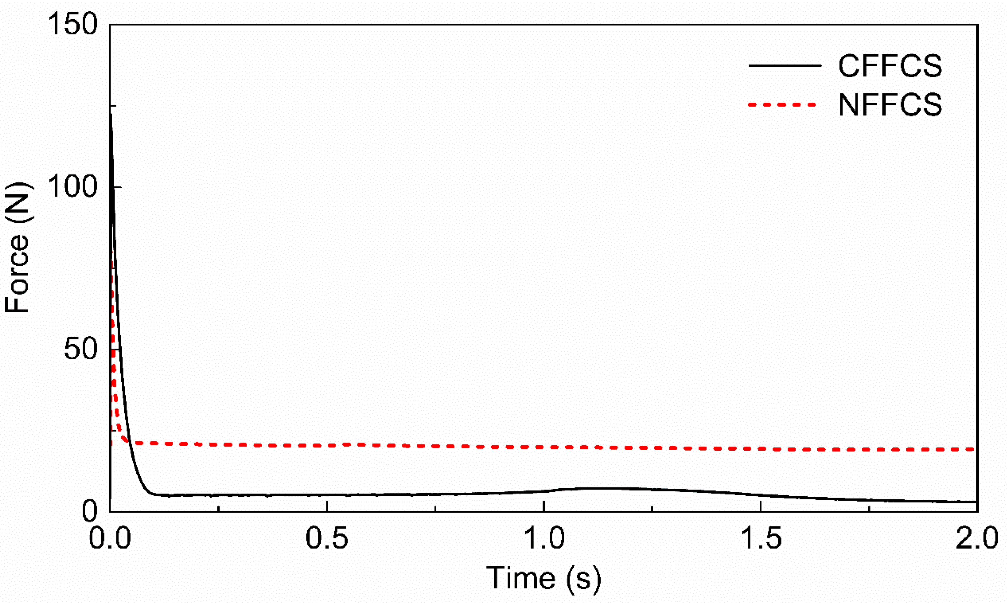
In order to observe the impact of hydraulic power on the coupling system, the axial resistance caused by the hydraulic oil to the valve opening during the coupling processes of CFFCS and NFFCS were monitored separately. The results of this study are summarized in Figure 10. The solid line represents the opening force results for the CFFCS and the dashed line represents the opening force results for the NFFCS. It can be observed that the maximum resistance for the CFFCS is about 122.3N, which occurs when the valve starts to be pushed (t = 0 s). This force then quickly drops to an approximately stable value (about 5N). When the valve is opened (t = 1.0 s), the thrust has a small increase and then stabilizes again. On the other hand, the NFFCS releases the pressure by opening the pin valve before the big valve is opened to achieve full conduction. When the pin valve is opened, the maximum axial thrust of 80.7N appears at the start of the push (t = 0 s), which then gradually decreases and stabilizes. It can be seen that the maximum axial resistance occurs at the same time (the beginning of the movement) in both the mechanisms. However, the presented NFFCS showed a resistance value that is 34% less than that showed by the CFFCS. Although the grid size at the gap has been divided to be an extremely small value, it still is difficult to obtain the data that is completely consistent with the actual due to the limitations of the dynamic mesh algorithm. However, the overall trends shown in the simulation can be considered as a reasonable depiction of the actual situation. Thus, we can safely infer that the design of the NFFCS can relieve the high pressure instantly with a small opening force so that the big valve can be easily opened to connect the hydraulic circuit.

4. Flow Characteristics and Optimization of the Coupler

When hydraulic oil flows in the coupling system, frictional resistance and turbulent energy loss occur due to the complicated structure inside the coupler, which causes a pressure drop between the inlet and the outlet [39]. In order to improve the efficiency of hydraulic power transmission while ensuring the best flow characteristics in the NFFCS design, a series of numerical simulations, comparisons, discussions and design optimizations were carried out, which are presented in this section. Firstly, the internal flow characteristics of the CFFCS and the initial design of the NFFCS are compared to ensure that the pressure drops of the two coupling systems are at the same level. Then, for the initial design of the NFFCS, a series of geometric optimizations are proposed and the flow characteristics are discussed, leading to the best final design.

4.1. Investigation Methods and Boundary Conditions

In this section, CFD analysis was performed on the CFFCS and the initial and optimized models of the NFFCS to observe their pressure, flow velocity and turbulent kinetic energy distributions. Among these outcomes, turbulence kinetic energy (TKE) which is one of the most common physical quantities in the turbulence model, is often used to observe the energy loss of liquid flow.
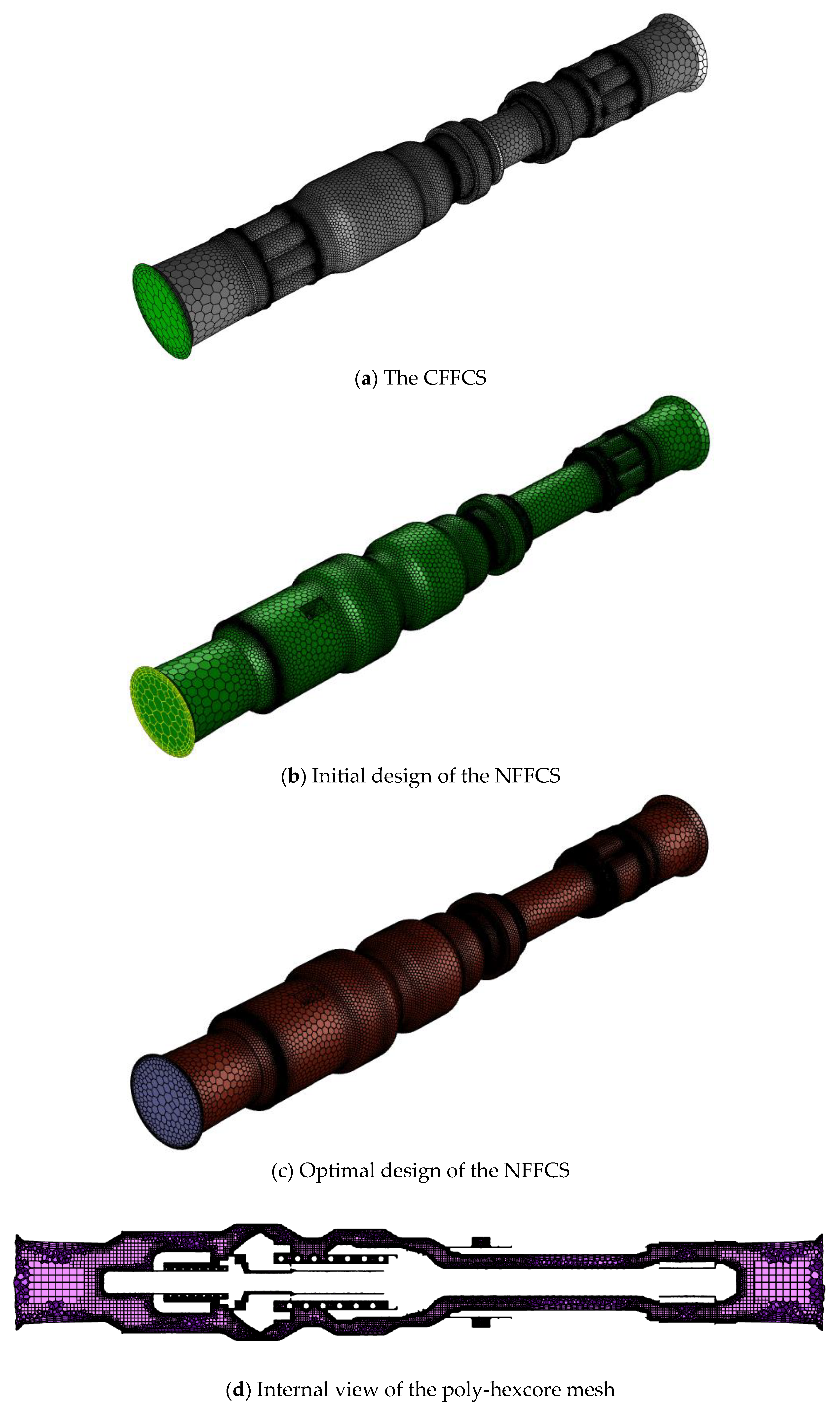
Figure 11a–c respectively show the mesh on the major internal components and the inlet boundary conditions for the CFFCS model, the initial NFFCS model and the optimized NFFCS model. In this simulation, Ansys Mosaic Meshing Technology was used to generate the mesh in the unique poly-hexcore form shown in Figure 11d. The poly-hexcore mesh provides higher accuracy and faster calculation speed for complex CFD problems [40].
The international standards ISO 16028 and ISO 4399 [12,17] give the pressure drop requirements and measurement methods for various sizes of flat-face type coupling systems. In this study, the coupling system size of 10 mm was modelled and observed as an example. The influence of the geometry of the small internal components and springs was considered in this investigation. The boundary conditions for simulations based on the ISO standard were set as mass-flow inlet = 0.3237 kg/s and pressure outlet = reference to atmospheric pressure. The hydraulic oil and turbulence models used are the same as those mentioned in Section 3.1.

4.2. Results and Discussion

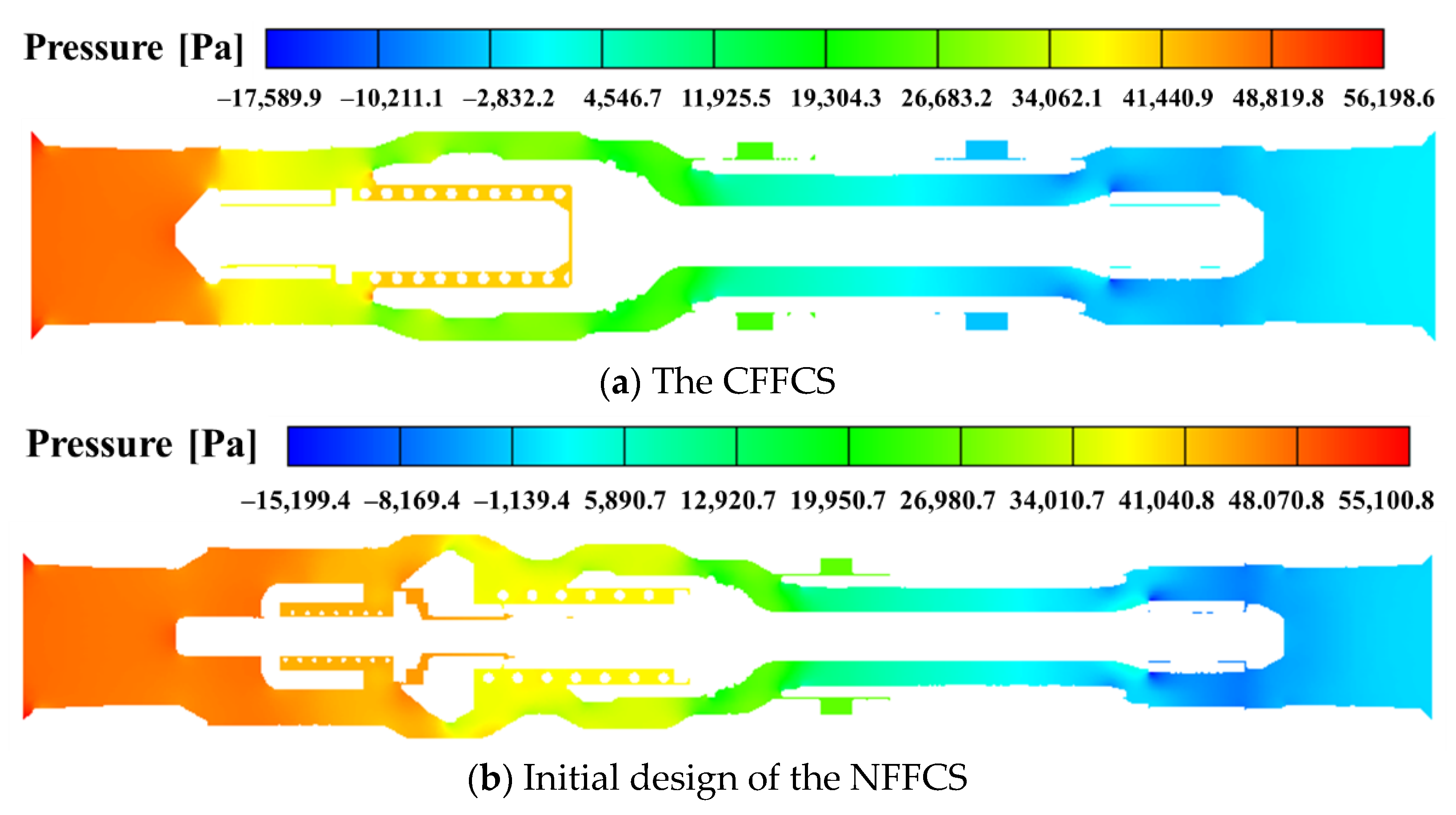
In order to more intuitively evaluate the flow characteristics of the NFFCS, they are compared with the simulation results of the CFFCS. The pressure drops of the CFFCS (50.76 kPa) and the NFFCS (49.49 kPa) were obtained through calculation of the average pressures at both sides of the inlet and outlet. It can be seen that although the internal geometry of the NFFCS is more complicated due to the inclusion of the instantaneous pressure relief device, its pressure drop is about 2.5% less than that of the CFFCS. Figure 12 shows the pressure distribution of the two flat-face type coupling systems. It can be seen that the pressure gradient distribution in the two systems in the steady state is uniform, and the pressure remains high at the inlet. The pressure drop around the guide pin of the valve at the inlet side of the CFFCS is more obvious, which is caused by the sudden decrease in the flow cross-sectional area and the increase in velocity. This is the main reason why the pressure drop of the CFFCS is higher than that of the NFFCS.
Figure 13 shows the velocity and streamline distribution results of the two flat-face coupling systems. By comparing the velocity distributions, it can be seen that there is a sharp increase in the velocity at the guide pin position near the inlet of the CFFCS. As mentioned before, due to the sudden reduction of the geometrical cross-sectional area, the surge in the flow rate of the hydraulic oil flowing through it leads to greater energy consumption, which results in the greater pressure drop in the CFFCS. The initial model of the NFFCS was designed with changes included mainly inside the plug while the socket was the same as that used in the CFFCS. It can be seen from Figure 13 that the streamlines in the sockets of the two coupling systems show obvious vortex phenomena near the outlet. This is due to the sudden increase in the flow cross-sectional area, which causes the flow rate to reduce and the pressure to increase sharply.
The pressure drop (49.49 kPa) of the initial NFFCS design was similar to that of the CFFCS and was within the standard limit (100 kPa) specified in ISO 16028. However, in order to obtain better flow characteristics, a series of design optimizations were carried out on the parts that were causing large amounts of energy loss, judged based on the turbulent kinetic energy observations.
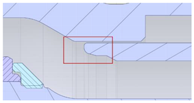
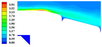
Figure 14 shows the turbulent kinetic energy distribution of the initial NFFCS design. It can be seen that the turbulent kinetic energy has a large value at positions 1 and 2 marked by the red dashed box, while a large area of energy loss occurs at position 3.
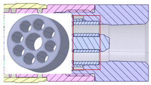
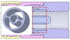
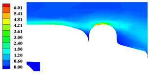
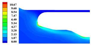
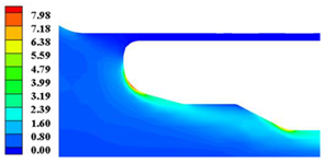
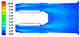
In order to obtain the optimal design, extensive sampling data of modifications were taken and simulations undertaken at these three positions. The specific geometric design and turbulent kinetic energy distribution before and after optimization are shown in Table 1 and Table 2, respectively.
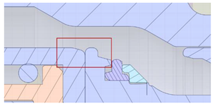
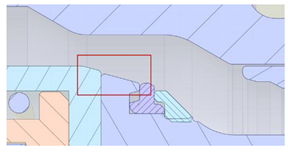
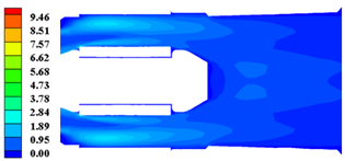
It can be observed that there is a large unevenness in position 1 where the plug valve and the socket pin make contact, which can be assumed to be the reason for the large energy loss. The unevenness of position 1 was smoothed as shown in Table 1 without changing the structural reliability of the parts. From the result of turbulent kinetic energy distribution at position 1 shown in Table 2, it can be seen that the maximum value for the optimized design is 4.27 m 2 s 2 , which is 28.9% less than the 6.01 m 2 s 2 value observed for the initial design.
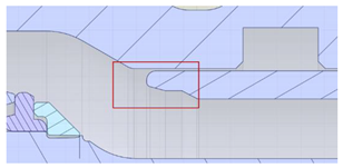
Similar to position 1, position 2 also has micro-geometric unevenness due to the improper chamfering of the component, which causes considerable energy loss at this position. By modifying the improper chamfer, the maximum value of the turbulent kinetic energy is reduced from 10.67 m 2 s 2 to 7.50 m 2 s 2 , which is a reduction of 29.7%. A comparison of the results at position 2 is shown in Table 2.
By observing the turbulent kinetic energy distribution at position 3 in the initial design, it is apparent that the vortex phenomenon is occurring at the end of the socket pin mentioned above. Thus, it can be inferred that the wide range of turbulent kinetic energy distribution here is caused by the interaction between the vortices. As shown in Table 1, at position 3, the pin fixing part of the initial design has eight small holes to allow passage of the hydraulic fluid. This design reduces the flow cross-sectional area, which leads to the vortex generation and energy loss problems. In the optimized design, the flow cross-sectional area on the pin fixing component is increased as much as possible while ensuring the stability of the rigid structure. From position 3 in Table 2, it can be seen that near the outlet, the large-area distribution of turbulent kinetic energy has been greatly improved in the optimized design, and the maximum value of turbulent kinetic energy has been reduced from 10.5 m 2 s 2 to 9.46   m 2 s 2 .
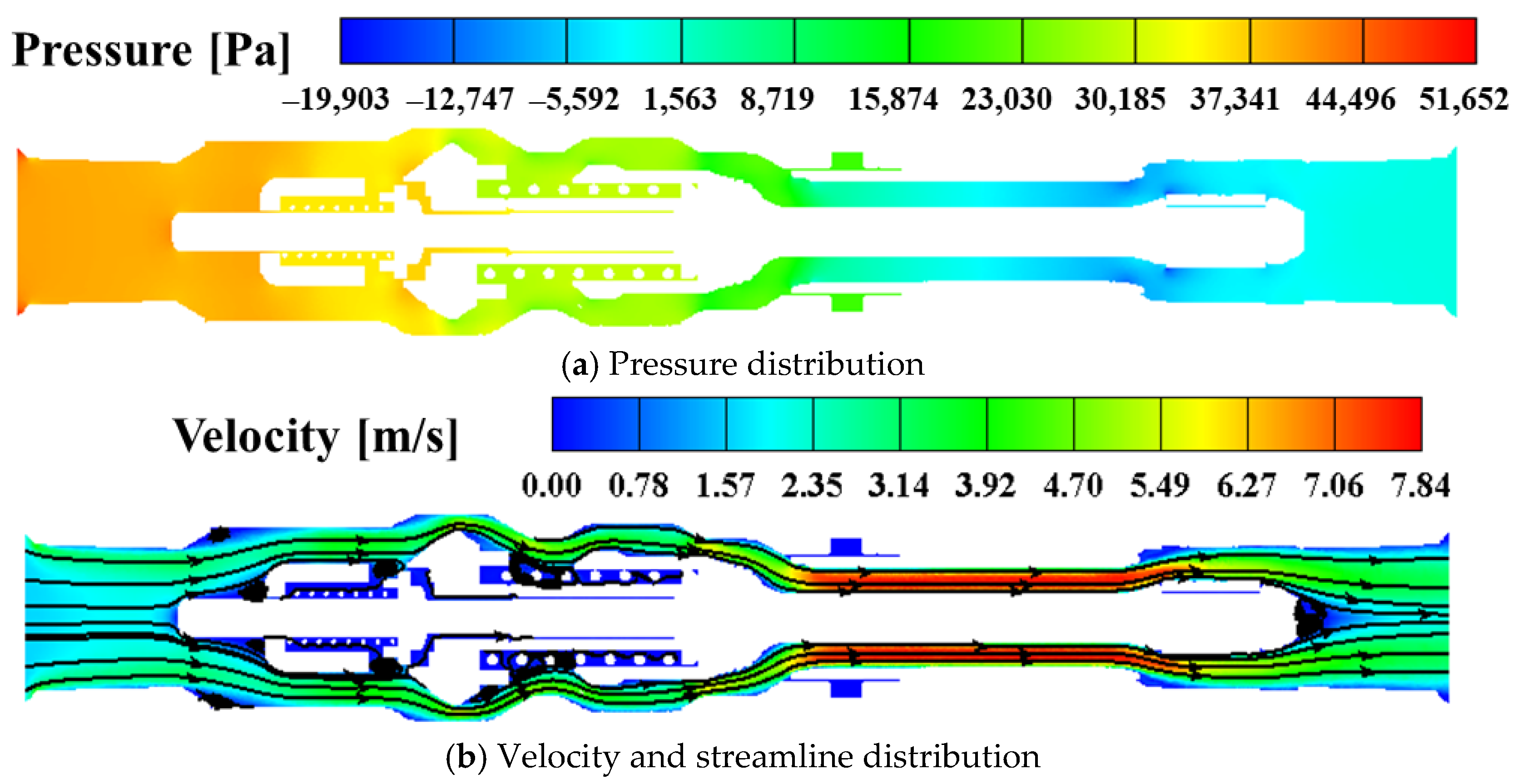
Similarly, the flow characteristics of the optimized NFFCS were also analyzed. The pressure distribution and the velocity and streamline distribution of the NFFCS are shown in Figure 15a,b, respectively. By calculating the average pressure difference between the inlet and the outlet, the pressure drop was found to be 42.79 kPa, which is 13.5% less than the pressure drop of the initial design (49.49 kPa). It can be seen from the pressure distribution that the overall pressure drop gradient distribution from inlet to outlet is uniform. By comparing Figure 15b with Figure 13b (initial design), it can be seen that the vortex phenomenon occurring at the outlet has also been significantly improved.

5. Conclusions

A novel flat-face coupling system (NFFCS) design incorporating an instantaneous pressure relief device based on Pascal’s law was presented in this research. The mechanism and kinematics of the NFFCS were explained and compared with a similar sized CFFCS. The flow characteristics and axial force during the opening process of the internal valve of the coupling systems were simulated using the CFD dynamic mesh algorithm. Combined with the Ansys Mosaic meshing technology, a series of numerical investigations were carried out on the flow characteristics of the entire system. Based on the distribution of turbulent kinetic energy, the energy-consuming locations of the initial design of NFFCS were determined and optimized. Thus, a design with optimal flow characteristics and hydraulic power transmission efficiency was obtained. The conclusions drawn from these investigations are summarized as follows:
The kinematics of the CFFCS and NFFCS are explained through the establishment of theoretical models of their coupling processes. In the NFFCS design, there is no major design change in the socket connector, while a high-pressure relief pin valve based on Pascal’s law is incorporated in the plug connector. During coupling, the pin valve connects the two chambers by overcoming a relatively small resistance force, which equalizes the pressures on both sides of the main valve so that it can be easily opened.
In order to verify the correctness of the NFFCS design, comparative simulations of the NFFCS and CFFCS coupling processes based on the novel CFD dynamic mesh technology were carried out. Analysis of the transient simulation results showed that the opening of the pin valve in the NFFCS has a balancing effect on the pressure difference between the neighboring chambers. Monitoring of the axial resistance during the opening of the valves of the two systems showed that the resistance generated by the NFFCS pin valve is 34% less than that of the CFFCS. This observation verifies the correctness of the NFFCS design.
Comparison of the steady-state flow characteristics of the CFFCS and the initial NFFCS design revealed that although the internal geometry of the NFFCS is more complicated due to the incorporation of the instantaneous pressure relief device, its pressure drop is about 2.5% less than that of the CFFCS. This confirms the feasibility of replacing CFFCS with NFFCS in future hydraulic power transmission applications.
To reduce further the energy consumed during the process of hydraulic power transmission through the NFFCS, the distribution of turbulent kinetic energy in the initial NFFCS design was observed. A series of geometric modifications and CFD simulations were carried out to devise the optimized NFFCS design with excellent hydraulic power transmission efficiency. The pressure drop of the optimized design is 42.79 kPa, which is 13.5% less than that of the initial design.
In summary, the easier installation (lesser thrust requirement) characteristics and smaller hydraulic power transmission loss of the proposed optimal NFFCS have been verified through a series of CFD numerical investigations. Additionally, the design and CFD-based investigation methodologies used in this research can serve as guides for future works related to the design of high-pressure hydraulic power transmission system components.

Author Contributions

Y.-T.W. and Z.Q. contributed equally. Conceptualization, Y.-T.W. and Z.Q.; methodology, A.E.; software, Y.-T.W.; validation, Z.Q. and S.-K.L.; formal analysis, S.-K.L.; investigation, Y.-T.W.; resources, A.E. and S.-K.L.; data curation, Y.-T.W. and Z.Q.; writing—original draft preparation, Y.-T.W. and Z.Q.; writing—review and editing, A.E. and S.-K.L.; visualization, Z.Q.; supervision, Y.-T.W.; project administration, S.-K.L.; funding acquisition, S.-K.L. All authors have read and agreed to the published version of the manuscript.

Funding

This work was supported by the Regional Leading Research Center of NRF and MOCIE (NRF-2019R1A5A808320112) & the Korea Small and Medium Business Administration (Grant No: S2848080).

Institutional Review Board Statement

Not applicable.

Informed Consent Statement

Not applicable.

Data Availability Statement

The raw/processed data required to reproduce these findings cannot be shared at this time as the data also forms part of an ongoing study.

Conflicts of Interest

The authors declared that they have no conflict of interest to this work.

References

  1. Liu, C.; Hu, M.; Gao, W.; Chen, J.; Zeng, Y.; Wei, D.; Yang, Q.; Bao, G. A high-precise model for the hydraulic power take-off of a raft-type wave energy converter. Energy 2021, 215, 119107. [Google Scholar] [CrossRef]
  2. Mizukami, H.; Otani, T.; Shimizu, J.; Hashimoto, K.; Sakaguchi, M.; Kawakami, Y.; Lim, H.; Takanishi, A. Investigation of Parallel Connection Circuit by Hydraulic Direct-Drive System for Biped Humanoid Robot Focusing on Human Running Motion. CISM Int. Cent. Mech. Sci. Courses Lect. 2021, 601, 34–42. [Google Scholar] [CrossRef]
  3. Ma, K.; Sun, D.; Sun, G.; Kan, Y.; Shi, J. Design and efficiency analysis of wet dual clutch transmission decentralised pump-controlled hydraulic system. Mech. Mach. Theory 2020, 154, 104003. [Google Scholar] [CrossRef]
  4. Kan, Y.; Sun, D.; Luo, Y.; Qin, D.; Shi, J.; Ma, K. Optimal design of the gear ratio of a power reflux hydraulic transmission system based on data mining. Mech. Mach. Theory 2019, 142, 103600. [Google Scholar] [CrossRef]
  5. Ma, B.; Yu, L.; Chen, M.; Li, H.Y.; Zheng, L.J. Numerical and experimental studies on the thermal characteristics of the clutch hydraulic system with provision for oil flow. Ind. Lubr. Tribol. 2019, 71, 733–740. [Google Scholar] [CrossRef]
  6. Lu, X.; Hu, C.; Chai, Y.; Ma, W. Experiment of transient flow field of hydrodynamic coupling under dynamic speed regulation with PIV. Huazhong Keji Daxue Xuebao (Ziran Kexue Ban) J. Huazhong Univ. Sci. Technol. (Nat. Sci. Ed.) 2019, 47, 50–54. [Google Scholar]
  7. Wang, J.; Zhao, J.; Li, W.; Jia, X.; Wei, P. Research and Improvement of the Hydraulic Suspension System for a Heavy Hydraulic Transport Vehicle. Appl. Sci. 2020, 10, 5220. [Google Scholar] [CrossRef]
  8. Truong, A.; An, T.; Ahn, K.K. Safety Operation of n-DOF Serial Hydraulic Manipulator in Constrained Motion with Consideration of Contact-Loss Fault. Appl. Sci. 2020, 10, 8107. [Google Scholar] [CrossRef]
  9. Sakaino, S.; Tsuji, T. Oil leakage and friction compensation for electro-hydrostatic actuator using drive-side and load-side encoders. In Proceedings of the IECON 2016—42nd Annual Conference of the IEEE Industrial Electronics Society, Florence, Italy, 23–26 October 2016; pp. 5088–5093. [Google Scholar]
  10. Rinneberg, S.; Teizer, J.; Kessler, S.; Günthner, W.A. Smart quick coupling system for safe equipment attachment selection and operation. In Proceedings of the 32nd International Symposium on Automation and Robotics in Construction, Oulu, Finland, 15–18 June 2015. [Google Scholar]
  11. Wang, W.; Zhang, S.; Mei, X.; Song, Y.; Zhang, H. Research on the quick coupler mechanism of near-pig receiver and launcher. In Proceedings of the International Conference on Pipelines and Trenchless Technology, Xi’an, China, 16–18 October 2013; pp. 1217–1225. [Google Scholar]
  12. Tang, Z.; Yun, C. Quick action coupling technology in full-automatic quick coupling device: A review. Zhejiang Daxue Xuebao (Gongxue Ban) J. Zhejiang Univ. (Eng. Sci.) 2017, 51, 461–470. [Google Scholar]
  13. Śliwiński, P. New Satellite Pumps. Key Eng. Mater. 2011, 490, 195–205. [Google Scholar] [CrossRef]
  14. Śliwiński, P. Influence of Water and Mineral Oil on the Leaks in Satellite Motor Commutation Unit Clearances. Pol. Marit. Res. 2017, 24, 58–67. [Google Scholar] [CrossRef] [Green Version]
  15. ISO. ISO Copyright Office Hydraulic Fluid Power—Dimensions and Requirements for Screw-to-Connect Quick-Action Couplings for Use at a Pressure of 72 MPa (720 bar); ISO 14540; International Organization for Standardization: Geneva, Switzerland, 2013. [Google Scholar]
  16. ISO. ISO Copyright Office Hydraulic Fluid Power—Quick-Action Couplings—Part 1: Dimensions and Requirements, IDT; ISO 7241; International Organization for Standardization: Geneva, Switzerland, 2014. [Google Scholar]
  17. ISO. ISO Copyright Office Hydraulic Fluid Power—Flush-Face Type, Quick-Action Couplings for Use at Pressures of 20MPa (200 bar) to 31.5 MPa (315 bar)—Specifications—AMENDMET1; ISO 16028; International Organization for Standardization: Geneva, Switzerland, 1999. [Google Scholar]
  18. Kanon, R.B. Increasing safety and efficiency. Hydrocarb. Eng. 2011, 16, 103–107. [Google Scholar]
  19. Sebastian, R.; Satheesh Kumar, S. Design of Quick Connect-Disconnect Hydraulic Coupling. Int. J. Recent Adv. Mech. Eng. 2014, 3, 43–54. [Google Scholar] [CrossRef] [Green Version]
  20. Strmčnik, E.; Majdič, F. Comparison of leakage level in water and oil hydraulics. Adv. Mech. Eng. 2017, 9, 1687814017737723. [Google Scholar] [CrossRef]
  21. Pezdirnik, J. Fluid flow through gaps in hydraulic components-(Liquid flow through gaps between paralell surfaces without relative velocity). Stroj. Vestn. 2001, 47, 210–216. [Google Scholar]
  22. Chen, J.; Wang, B.; Liu, D.; Yang, K. Study on the Dynamic Characteristics of a Hydraulic Continuous Variable Compression Ratio System. Appl. Sci. 2019, 9, 4484. [Google Scholar] [CrossRef] [Green Version]
  23. Ferras, D.; Manso, P.; Schleiss, A.; Covas, D. One-Dimensional Fluid–Structure Interaction Models in Pressurized Fluid-Filled Pipes: A Review. Appl. Sci. 2018, 8, 1844. [Google Scholar] [CrossRef] [Green Version]
  24. Amirante, R.; Vescovo, G.D.; Lippolis, A. Flow forces analysis of an open center hydraulic directional control valve sliding spool. Energy Convers. Manag. 2006, 47, 114–131. [Google Scholar] [CrossRef]
  25. Selvam, R.; Loganathan, G.B. Product detail and analysis of hydraulic quick releasing coupling. Mater. Today Proc. 2020, 22, 751–755. [Google Scholar] [CrossRef]
  26. Qin, Z.; Wu, Y.T.; Lyu, S.K. A Review of Recent Advances in Design Optimization of Gearbox. Int. J. Precis. Eng. Manuf. 2018, 19, 1753–1762. [Google Scholar] [CrossRef]
  27. Qin, Z.; Wu, Y.T.; Eizad, A.; Jeon, N.S.; Kim, D.S.; Lyu, S.K. A Study on Simulation Based Validation of Optimized Design of High Precision Rotating Unit for Processing Machinery. Int. J. Precis. Eng. Manuf. 2019, 20, 1601–1609. [Google Scholar] [CrossRef]
  28. Qin, Z.; Wu, Y.T.; Eizad, A.; Lee, K.H.; Lyu, S.K. Design and evaluation of two-stage planetary gearbox for special-purpose industrial machinery. J. Mech. Sci. Technol. 2019, 33, 5943–5950. [Google Scholar] [CrossRef]
  29. Qin, Z.; Son, H.I.; Lyu, S.K. Design of anti-vibration mounting for 140A class alternator for vehicles. J. Mech. Sci. Technol. 2018, 32, 5233–5239. [Google Scholar] [CrossRef]
  30. Qin, Z.; Zhang, Q.; Wu, Y.T.; Eizad, A.; Lyu, S.K. Experimentally Validated Geometry Modification Simulation for Improving Noise Performance of CVT Gearbox for Vehicles. Int. J. Precis. Eng. Manuf. 2019, 20, 1969–1977. [Google Scholar] [CrossRef]
  31. Qin, Z.; Wu, Y.; Huang, A.; Lyu, S.; Sutherland, J. Theoretical Design of a Novel Vibration Energy Absorbing Mechanism for Cables. Appl. Sci. 2020, 10, 5309. [Google Scholar] [CrossRef]
  32. Wang, H.; Zhao, Y.; Wang, J.; Kong, X.; Liu, H.; Li, K.; Wang, X. Numerical simulation of flow characteristics for a labyrinth passage in a pressure valve. J. Hydrodyn. Ser. B 2016, 28, 629–636. [Google Scholar] [CrossRef]
  33. Li, W.; Gao, Z.; Jin, Z.; Qian, J. Transient Study of Flow and Cavitation Inside a Bileaflet Mechanical Heart Valve. Appl. Sci. 2020, 10, 2548. [Google Scholar] [CrossRef] [Green Version]
  34. Li, J.; Gao, Z.; Wu, H.; Jin, Z. Numerical Investigation of Methodologies for Cavitation Suppression Inside Globe Valves. Appl. Sci. 2020, 10, 5541. [Google Scholar] [CrossRef]
  35. Fasquelle, A.; Pellé, J.; Harmand, S.; Shevchuk, I.V. Numerical Study of Convective Heat Transfer Enhancement in a Pipe Rotating Around a Parallel Axis. J. Heat Transf. 2014, 136, 051901. [Google Scholar] [CrossRef]
  36. Riemslagh, K.; Vierendeels, J.; Dick, E. Simulation of Incompressible Flow in Moving Geometries; Von Karman Institute for Fluid Dynamics: Sint-Genesius-Rode, Belgium, 1998; 24p. [Google Scholar]
  37. Menéndez Blanco, A.; Fernández Oro, J.M. Unsteady numerical simulation of an air-operated piston pump for lubricating greases using dynamic meshes. Comput. Fluids 2012, 57, 138–150. [Google Scholar] [CrossRef]
  38. Siddique, W.; El-Gabry, L.; Shevchuk, I.V.; Fransson, T.H. Validation and Analysis of Numerical Results for a Two-Pass Trapezoidal Channel With Different Cooling Configurations of Trailing Edge. J. Turbomach. 2013, 135, 110271–110278. [Google Scholar] [CrossRef] [PubMed] [Green Version]
  39. Li, S.; Yang, J. Effects of Inclination Angles on Stepped Chute Flows. Appl. Sci. 2020, 10, 6202. [Google Scholar] [CrossRef]
  40. Zore, K.; Caridi, D.; Lockley, I. Fast and Accurate Prediction of Vehicle Aerodynamics Using Ansys Mosaic Mesh. SAE Tech. Pap. 2020, 1, 5011. [Google Scholar] [CrossRef]
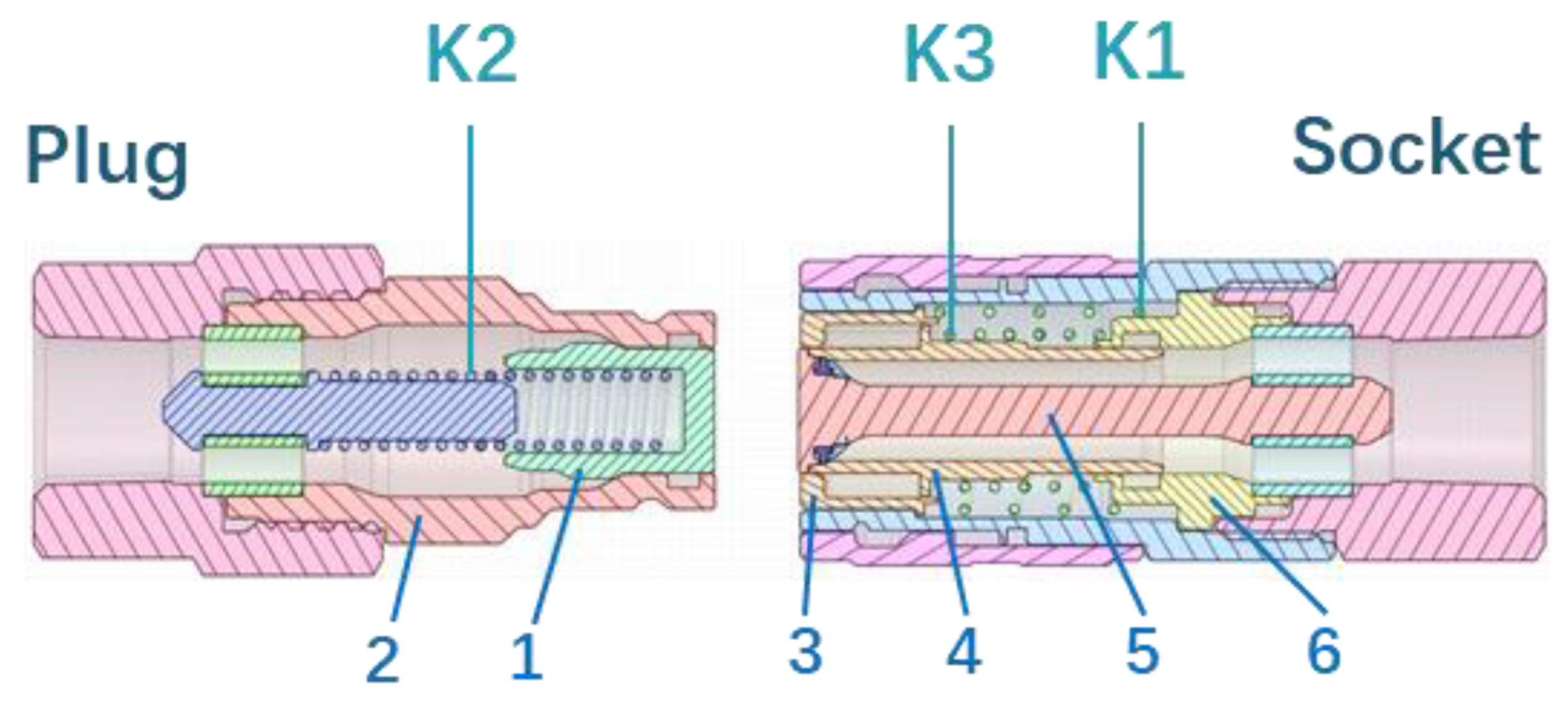
Figure 1. Internal mechanism of the conventional flat-face coupling system (CFFCS).
Applsci 11 00388 g001
Figure 2. Kinematics of the CFFCS.
Applsci 11 00388 g002
Figure 3. Theoretical modeling of the different processes of the CFFCS, (a) Process 1 and (b) Process 2.
Applsci 11 00388 g003aApplsci 11 00388 g003b
Figure 4. Internal mechanism of the novel flat-face coupling system (NFFCS).
Applsci 11 00388 g004
Figure 5. Kinematics of the NFFCS.
Applsci 11 00388 g005
Figure 6. Theoretical modeling of the different processes of the NFFCS, (a) Process 1, (b) Process 2, (c) Process 3 and (d) Process 4.
Applsci 11 00388 g006
Figure 7. Meshing of the two models, (a) CFFCS and (b) NFFCS.
Applsci 11 00388 g007
Figure 8. Instantaneous pressure and velocity distributions at different times during the coupling process of the CFFCS, (a) t = 0.5 s, (b) t = 1.0 s and (c) t = 2.0 s.
Applsci 11 00388 g008
Figure 9. Instantaneous pressure and velocity distributions at different times during the coupling process of the NFFCS, (a) t = 0 s, (b) t = 0.2 s, (c) t = 0.4 s, (d) t = 1 s and (e) t = 2 s.
Applsci 11 00388 g009aApplsci 11 00388 g009b
Figure 10. Comparison of the valve opening forces required by the CFFCS and NFFCS.
Applsci 11 00388 g010
Figure 11. Meshing and inlet boundary conditions, (a) The CFFCS, (b) Initial design of the NFFCS, (c) Optimal design of the NFFCS and (d) Internal view of the poly-hexcore mesh.
Applsci 11 00388 g011
Figure 12. Pressure distribution results for the two flat–face coupling systems, (a) The CFFCS and (b) Initial design of the NFFCS.
Applsci 11 00388 g012
Figure 13. Velocity and streamline distributions for the two flat-face coupling systems, (a) The CFFCS and (b) Initial design of the NFFCS.
Applsci 11 00388 g013
Figure 14. The turbulent kinetic energy distribution of the initial NFFCS design.
Applsci 11 00388 g014
Figure 15. Flow characteristics of the optimized NFFCS design, (a) Pressure distribution and (b) Velocity and streamline distribution.
Applsci 11 00388 g015
Table 1. The geometrical design modifications made in the initial design to obtain the optimized design.
PositionInitial DesignOptimized Design
1 Applsci 11 00388 i001 Applsci 11 00388 i002
2 Applsci 11 00388 i003 Applsci 11 00388 i004
3 Applsci 11 00388 i005 Applsci 11 00388 i006
Table 2. Comparison of the turbulent kinetic energy distribution results for the initial and optimized designs.
PositionInitial DesignOptimized Design
1 Applsci 11 00388 i007 Applsci 11 00388 i008
2 Applsci 11 00388 i009 Applsci 11 00388 i010
3 Applsci 11 00388 i011 Applsci 11 00388 i012
Publisher’s Note: MDPI stays neutral with regard to jurisdictional claims in published maps and institutional affiliations.