1. Introduction
Intelligent control and perception methods, which include classic techniques such as fuzzy logic, neural networks, genetic algorithms… to recent advances in deep learning and machine learning, play a significant role in applied sciences, with practical applications in a wide variety of domains. One of the main advantages of these methods is that they can be used as a powerful tool both to represent expert knowledge, optimize systems or extract and discover relevant information from a dataset autonomously, among others.
Applied science requires testbeds, and experimental setups, to perform experiments and to validate the results of the application of the methods in practice. This is especially relevant from an educational point of view, since these tools can significantly contribute in the teaching and learning of different techniques. Moreover, nowadays, popular massive open online courses (MOOC) have changed the way technicians and Engineers can update and expand their knowledge, and provide their students with an remote software platform, such as Matlab or Python, but generally lacks implementation of tasks in real systems. In that sense, having real low-cost systems, with a variety of sensors and actuators, that can be applied in different scenarios and real tasks, would be a very valuable tool that would leverage the dissemination of the use of these methods and enhance learning outcomes, both in classroom and online courses.
In recent years, smartphones have been shown as a disruptive technology universally used, since they allow a wide variety of tasks to be carried out, with a growing computing capacity in addition to incorporating several, even advanced, sensors such as cameras, GPS, accelerometers, gyroscopes, magnetometers, interactive screen and communications systems (3G-5G, Wi-Fi, Bluetooth, …) for connection with other processes or systems, at a relatively low price. That is why there is a growing interest in these devices from the point of view of applied science, both in their use as a tool or integrated with other systems [
1,
2,
3,
4,
5,
6]. Thus, in [
1], a smartphone-based platform for data-intensive embedded detection applications is presented, including several case studies. The problem of efficient interior positioning in real time using iBeacons and smartphone sensors based on fusion techniques is addressed in [
2]. Other authors introduce new applications and interactions with mobiles using smartphones with kinetic capabilities that use wheels [
3] or legs [
4]. In [
5], a low-cost remotely controlled augmented reality car using the capabilities of a smartphone and online software services is presented. On the other hand, [
6] analyzes various reliability and security issues when using Android in industrial control systems, ranging from real-time requirements to hardware and cyber attacks.
Moreover, in educational settings, almost all students have an advanced cell phone so using it as an educational tool could be a motivating element for students. The integration of a smartphone in an educational robot would allow to have a system with many advanced sensors at a low cost compared to other higher cost educational robots. To achieve this integration, it is necessary to connect or link the smartphone to an input-output microcontroller board, such as Arduino, IOIO, ESP8266, … Arduino [
7] has become an open standard, and is being widely used as a daily tool in many schools, and universities in education in electronics, control and robotics or even at industrial level [
8,
9,
10,
11]. For example, paper [
8] presents Simulink exercises that use Arduino as low-cost hardware for PID control of a DC motor. With remote learners in mind, authors in [
9] present an Arduino platform and a hardware-based open lab kit that allows students to use inexpensive course-specific hardware to complete lab exercises at home. On the other hand, paper [
10] presents the use of programmable logic controllers (PLC) and Industrial Internet of Things (IIoT), based on Arduino and Raspberry-Pi, to control a two-tank process, including fuzzy PID and fault detection with extended Kalman filter, among others. In [
11], the authors discuss the advantages of using Arduino in an undergraduate mechatronics course organized in a competition framework in which students build a mobile robot.
At this point, it is worth highlighting the relevance from the point of view of robotics and its applications of the Robot Operating System (ROS) [
12]. It is an open robotics software framework that has become a standard interface for robots in the academic world with exponential growth. One of the main benefits of ROS is that it naturally integrates robots into networks, facilitates multi-robot communications, and makes the robotic cloud possible. In addition, it greatly facilitates integration with computer vision or 3D modeling and simulation tools, such as OpenCV, Gazebo or Matlab among others. In [
13], real-time characteristics of the new ROS 2.0 in multiagent robot systems are evaluated. Beyond the technical aspects, a very valuable aspect that Arduino and ROS share is their open nature, with a large and active community of developers and users.
The increase in the use of educational robots in classrooms [
14] and labs has been made possible thanks to the appearance of low or middle-cost educational robotics kits, which are mechanically easy to construct. So there exists a wide variety of robotics kits (see [
15] and the references there in for a review of educational robotics kits, including cost an applications), several of them integrated with ROS [
16,
17] and/or using smartphones [
18,
19].
In a previous work [
19], we presented a low-cost educational mobile robot, called Andruino-A1 based on Android and Arduino as an open system (hardware and software). It was created to be used as a robotic educational tool to enable professional education and training for adults (VET) and undergraduate students who perform learning tasks with real robots, in the laboratory, in the classroom or even as homework, according to educational policy. “BYOR: Bring [Build] Your Own Robot.” Recently, a new Andruino robot, Andruino-R2, has been briefly introduced in [
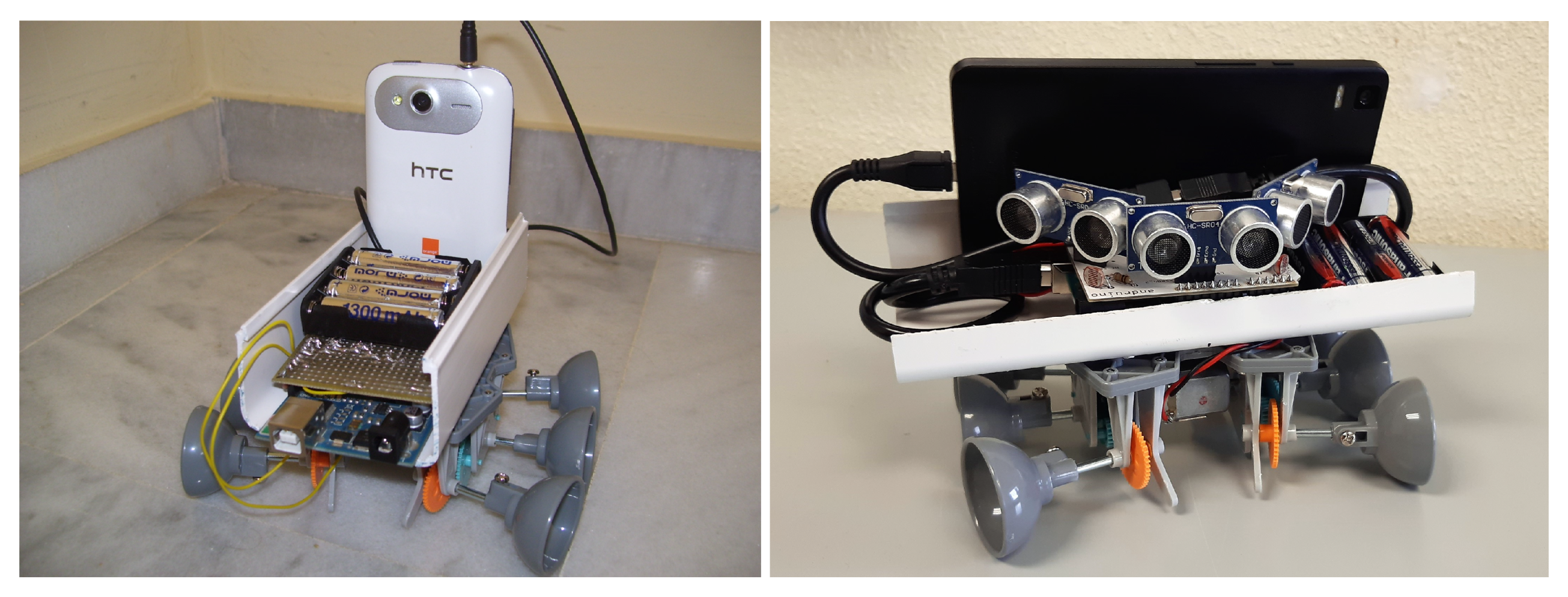
20]. In this article we present a detailed description of the Andruino-R2 robot (see
Figure 1) and a comparison with Andruino-A1, highlighting the advantages of the new system. It is integrated with ROS, and allows the utilization of multiple sensors and communication resources: light sensors, ultrasonic sensors, GPS, camera, accelerometer, compass, Bluetooth, WiFi… The construction of the robot itself, together with its programming, provide learning outcomes in various areas. These sensors and resources can be applied in a simple way to carry out advanced tasks using real systems, but also maintaining the possibility of their integration with environments and simulation tools thanks to the 3D models developed.
In addition, this article focuses on examples of how Andruino-R2 can be applied in the areas of intelligent control, machine vision and machine learning, maintaining a didactic approach, to illustrate its versatility and simplicity. These techniques are increasingly relevant and some authors demand that they be incorporated into the ordinary curriculum of VET and engineering students [
21]. However, in many cases, only simulation environments are considered or commercial educational robots are used with a higher cost [
22,
23,
24]. Low-cost robots have also been used, but generally with a very specific approach as in [
25] where the implementation of fuzzy controllers in embedded systems is shown. On the contrary Andruino-R2, allows to acquire the holistic vision that the construction of a complete system offers the student, in addition to being flexible enough to implement different sets of techniques in a simple way.
Specifically, a practical application has been made to visual tracking of trajectories integrated with a Fuzzy Collision Risk system, which avoids collision with obstacles ahead at a close distance, in a qualitative way. Likewise, Machine Learning has also been applied to solve the problem of robot localization based on Wi-Fi signals in a three-room scenario. Three supervised multiclass classification algorithms have been applied and compared, Multiclass Logistic Regression (MLR), Multiclass Neural Network (MNN) and Multiclass Decision Forest (MDF), in addition to proposing improvements based on expanding the dataset using new context features.
Therefore, Andruino-R2 is a versatile and valuable tool for education, research and innovation in several domains, but it maintains its simplicity, its low cost and its open source.
The paper is organized as follows:
Section 2 presents the design criteria on which Andruino robots are based.
Section 3 and
Section 4 provide details of both the hardware and the software respectively of the new Andruino-R2 robot, the differences with Andruino-A1, as well as the relevant aspects that they contribute from an educational point of view. In
Section 5 computer vision and fuzzy logic are applied to visually track a trajectory integrated with a fuzzy collision risk system.
Section 6 deals with applied Machine Learning to solve the problem of robot localization based on Wi-Fi signals collected by the robot itself. Finally,
Section 7 presents conclusions.
3. Andruino Hardware and Sensors
The hardware design of the Andruino robots follows the principles indicated above. Therefore, the robot must be built with minimal hardware components to make the assembly process as simple and modular as possible. As shown in
Figure 2, each robot consists primarily of a mobile base, an Arduino with a specially designed shield, batteries, and an Android device. The characteristics of the shield, onboard sensors and communication links, among others, make the difference between both versions, as will be seen below.
The first item is the mobile base which includes 3–6 volt DC motors and gearboxes. It is important to note that this base can easily be replaced by any other base purchased on the market or, better yet, if possible, as is the case with mechatronics courses, the students themselves could design and build their own bases. We must draw attention to the fact that the absence of encoders or other electronic elements in the robotic base makes this much simpler, interchangeable and economical, which is why only four cables for DC motors connect the electronics to the selected base. In this way, the robot can be approximated using a simple kinematic model:
where
v and
, linear and angular velocity respectively, are the input variables.
One of the principles of Andruino is to take advantage of the experience of the developers to improve the system. Thus, while in Andruino-A1 [
19] a unidirectional audio connection (using simple and asynchronous low bit rate communication with frequency shift modulation) was used to link Arduino with Android, in Andruino-R2 the connection it is done using a two-way serial communication via USB On-The-Go (OTG). In this way, the Android phone acts as a host on the USB bus, in a similar role to that of a PC in standard Arduino communication. The use of USB OTG presents another additional advantage, since it allows the sensors of the shield and the Arduino itself to work with the battery of the Android device (generally a lithium-ion battery with more than 2000 mAh). Therefore, there is another power system only for motors, which is based on AAA batteries. This separation of power sources makes it easy to reuse the development in other larger autonomous robots, so replacing the motors and batteries would be enough to power 12 V or 24 V DC motors.
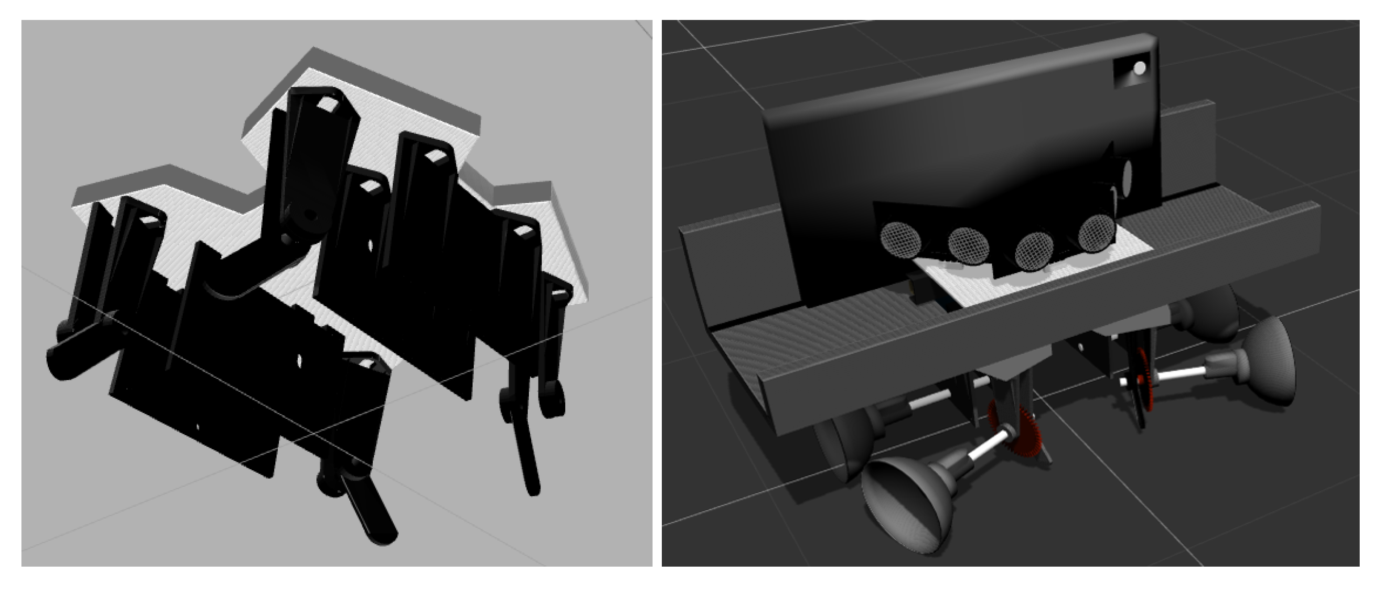
An important feature in Andruino-R2 is the newly developed shield, as shown in
Figure 3. It is designed on a standard size Arduino board for compatibility and integrates three light sensors (LDR) and three ultrasonic sensors, in addition to a dual line integrated circuit to implement the H-Bridge to control the DC motors. Regarding the LDRs, two of them were placed on the left and right side corners of the PCB in a symmetrical configuration, under the shadow of ultrasonic sensors, this location is intended to detect side light from doors and windows in an indoor environment. There is also a center up LDR, which tries to detect the ceiling light indoors.
On the other hand, the shield also supports three ultrasonic low-cost range sensors. An ultrasonic sensor is placed parallel to the cell phone, while the other two are in the left and right position, rotated 45 degrees, to obtain a front range sensor from 30
to 150
. In addition to avoiding collisions in a 2D environment, as will be shown in
Section 5, ultrasonic sensors are also used in the calibration process to obtain an estimate of linear velocity.
It should be noted that the shield design makes it easier to assemble the robot hardware, reducing hardware construction flaws. However, since the number of components is very low and SMD components are not used, it could also be mounted on a breadboard. The electronic design, from the schematic to the PCB, was carried out with the free Fritzing tool [
26], and is published as open hardware, so that students can improve the design or modification of the hardware to meet the requirements of their own projects and easily produce their own electronic shields.
In summary, the Andruino-R2 robot is equipped with three ultrasonic sensors and three light sensors and those provided by the smartphone: camera, accelerometer, gyroscope, magnetometer, GPS, Bluetooth and Wi-Fi. Smartphone sensors are used to measure speeds and orientation, which are also used to improve low-level control of motors.
From an educational point of view, Andruino’s hardware development contributes to the following learning objectives, among others [
19]:
Basic knowledge of electronics, soldering and construction of electronic prototypes, mainly Arduino shields.
Knowledge of the DC motor control through the H-bridge.
Knowledge of the Arduino open hardware architecture and shields.
Basic skills in computer aided electronic design and the use of CAD/CAE
5. Applying Computer Vision and Fuzzy Logic
As a first example, the utility of Andruino-R2 is presented to validate the practical application of computer vision [
35] and fuzzy logic techniques in mobile robot navigation in the classroom. Specifically, Andruino-R2 must visually follow a path, marked by a green line, in addition to stopping when it detects an obstacle ahead close enough, in a qualitative sense. Fuzzy systems have been widely applied in robotics for intelligent navigation [
36], visual path tracking [
37], optimal obstacle avoidance in underwater vehicles [
38] or design of fuzzy controllers for embedded systems [
25], to name a few recent developments.
In this way, students have the opportunity to acquire and apply the basics of how a rule-based knowledge decision system works. The student must identify the input and output variables, the attributes that define them and their membership functions, in addition to expressing the ruleset of expert knowledge that solve the problem. Later, the student will have to implement the code that makes it possible to obtain the output from the input using the knowledge base defined above. Specifically, the four basic stages of a fuzzy logic system will be identified to infer an output from the inputs: fuzzyfication, inference, composition and defuzzification. First the conversion of a quantitative input value to a qualitative one using the membership functions (fuzzication); second, the logical operators are applied to evaluate the degree of truth of each rule and obtain the qualitative output of each one of them (inference); third, the qualitative outputs of each rule are combined into a single system output (composition); finally, the qualitative output has to be converted to a crisp quantitative output (defuzzification), which can be used in the system.
To develop this objective, students begin by acquiring and applying the basic notions of image processing and feedback control. To do this, using the smartphone camera, the robot must detect a line of a certain color on the ground, stand on it and start to follow it. Once successful, they must apply fuzzy logic to get it to stop if the frontal ultrasound sensor detects an object close enough, and stay stopped until the path is clear again.
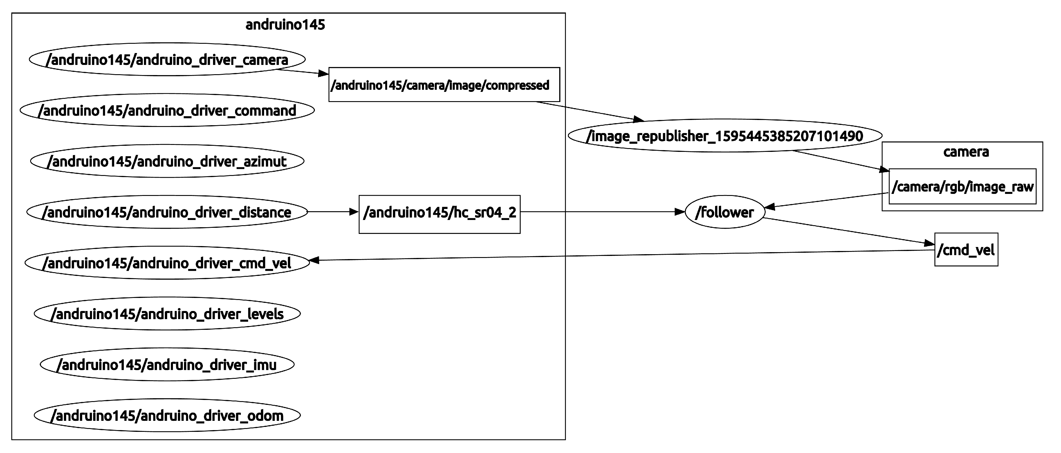
Figure 4 shows the ROS computation graph for this task. Thus, the
task subscribes to both the measurement from the front ultrasonic sensor (
) and to the image from the camera (which was previously converted into raw format,
). With those inputs, it has to compute the desired linear (
v) and angular (
) velocities (
) that are sent to the Andruino-R2 (
), and translated into actual PWM signals for each DC motor in the Andruino shield.
One of the main advantages of ROS is that it greatly facilitates integration with tools for computer vision such as OpenCV. Image processing is done easily using basic commands from the OpenCV library. In this way, students begin by learning how to acquire an RGB (red, Green, Blue) picture frame and convert it to the HSV (Hue, Saturation, Value) color space where it is easier to represent a color. They then identify the color of the line to follow, set the HSV image threshold for a range of line color, and apply the resulting mask to the original image. The mask is also used to calculate the destination point on the line at a distance ahead.
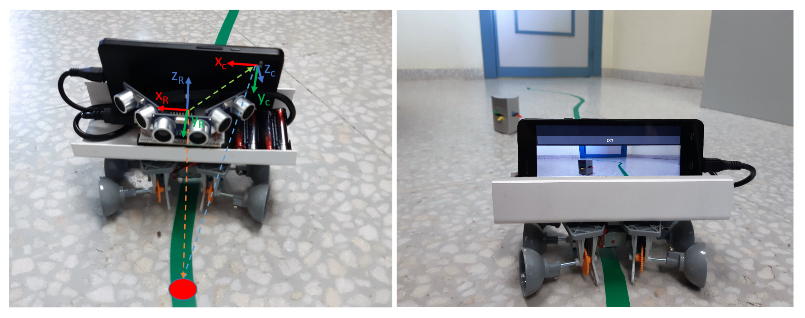
To calculate the actual deviation of the Andruino-R2 robot with respect to the line, it is necessary to take into account that the camera’s reference system is not centered with respect to the robot’s reference frame, as can be seen in
Figure 7. Therefore, when the robot is centered on the line, the tracking point will not appear centered on the image. Thus, a reference system change must be applied before calculating the lateral error which is fed back through a proportional controller to compute the desired linear (
) and angular velocities (
).
Figure 8 shows the control screen with the different steps, starting with the image obtained from the robot’s camera, its conversion into the HSV frame, the result of applying the mask to the original image and finally the image showing the selected reference point on the line, the computed steering action (in blue) and the distance measured by the front ultrasonic sensor (in green).
As a next step, to get the robot to stop when there is an “obstacle close enough ahead”, students implement a Fuzzy Collision Risk module, which is a first contact with qualitative knowledge systems using Fuzzy Logic. Thus, taking as input the distance measured by the front ultrasonic sensor, the fuzzy system must calculate a collision risk index (RiskLevel), in the range . This index will be used later to modify the velocities () calculated by visual tracking before being applied to the robot.
For the fuzzy system, a simple Takagi–Sugeno system with one input and one output is considered, as shown in
Figure 9. The input variable,
, is defined by three linguistic terms (close, medium and far) and their corresponding membership functions (
,
and
) that are set by the student. The output variable,
, is defined by three singleton values:
,
,
. The following three rules complete the fuzzy system:
Given a crisp measurement (
) of the ultrasonic sensor, the degree of truth of each rule, or weight (
), is evaluated (Fuzzyfication). Since in this case only one variable and one label are considered in the antecedents of each rule, the weight of the rule will be given directly by the involved membership function (
). Then, the consequent of each rule (
) is weighted by its degree of truth by using product operator, yielding the rule output (Inference). To obtain the unique output of the fuzzy system, it is necessary to combine the output of each of the rules (composition and defuzzification). In this case, a weighted average of the different rules has been selected. Therefore, the output of the Fuzzy Collision Risk system can be calculated using the next expression:
which means that
is a nonlinear function of
as shown in
Figure 10. This index is then applied to correct the velocities (
) calculated by visual tracking before being applied to the robot (see Equation (
1)):
Figure 11 shows the application of the aforementioned controller to an experiment with Andruino-R2 starting off from a green line, approaching it and keeping centered on it. As the obstacle approaches, the risk level increases and the robot’s speed decreases until the Andruino-R2 stops when the obstacle ahead is close enough (sensor measurement is also shown in red and displayed a warning message).
To illustrate the efficiency of the controller, a second, small, cylindrical obstacle was placed at the curve end in the path, making it difficult to be detected by the ultrasonic sensor. Thus, once the first obstacle is removed, the robot continues to advance as shown in
Figure 12. However, as can be seen, the second obstacle is not detected by the front ultrasonic sensor until exiting the curve when it is very close, but the control system is precise enough to stop just 9 cm from the obstacle. Once removed, the vehicle continues to track the path until it ends.
As a direct extension of the work, the student can modify the Fuzzy Collision Risk system to also consider the speed of the robot when assessing the risk of collision. In this way, a second input is added to the system,
, with two adjectives (
and
) as shown in
Figure 13. The rule base is updated accordingly resulting in:
In this case, since there are several variables in the antecedent of each rule, the weight of each rule will depend on the level of membership of each variable to each membership function. The product has been selected as the AND operator. In this way the weight of each rule will be given by the product of the membership functions, that is,
. The output of the new fuzzy system is given by:
which is a nonlinear surface depending on
and
, as shown in
Figure 14. The rest of the system does not have to be modified.
Finally, in advanced mode, the student can incorporate the so-called direction of attention from the trajectory of the robot to the Fuzzy Collision Risk system to take into account the lateral ultrasonic sensors when the robot moves in a curve in such a way that it can anticipate situations such as those shown with the second obstacle in the experiment.
6. Applying Machine Learning Based on Cloud Services
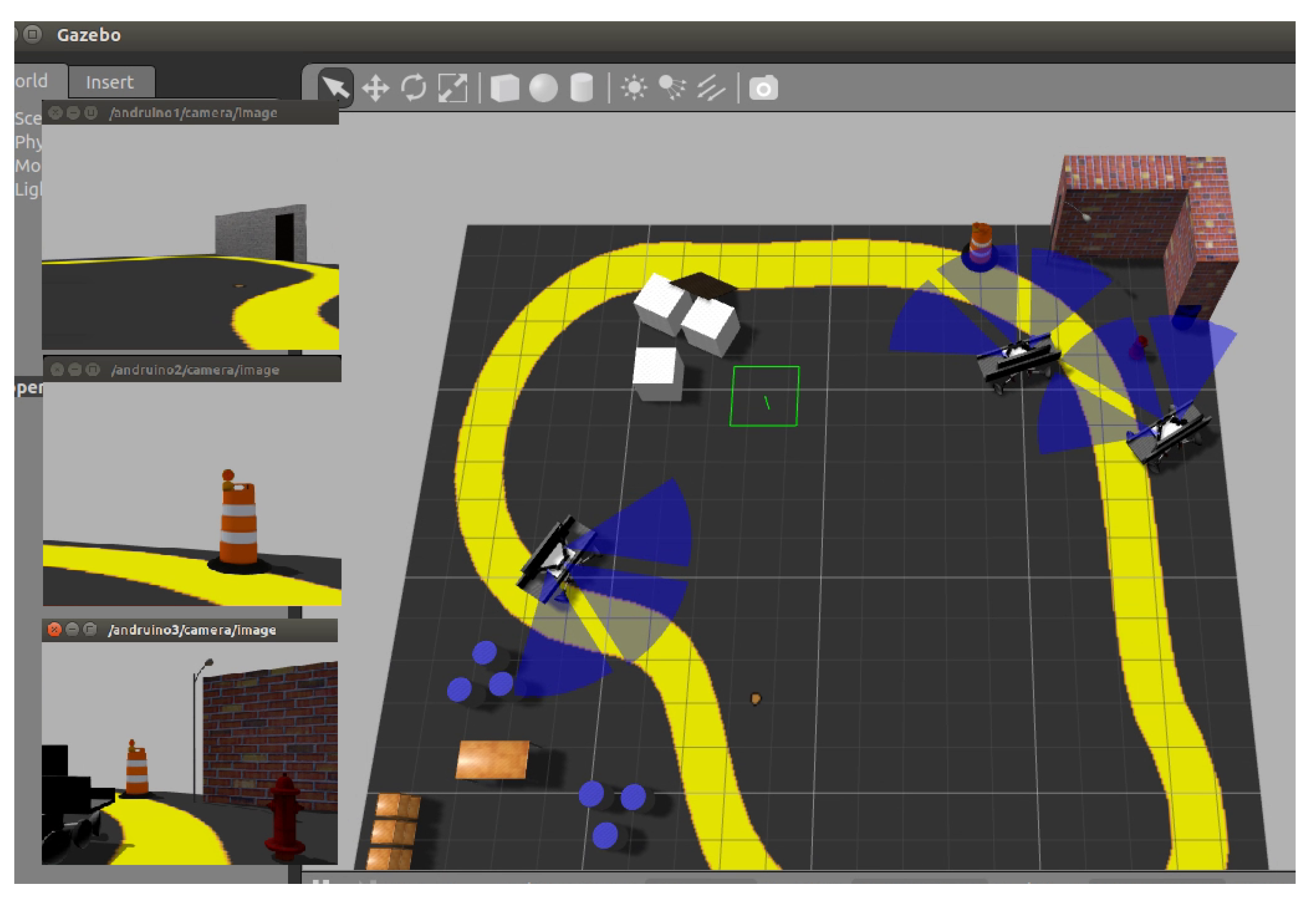
As a second example, the utility of Andruino-R2 is presented to validate the practical application of machine learning techniques using cloud services. Specifically, a system will be developed that allows Andruino-R2, based on the data collected from the Wi-Fi signals, to identify in which room it is located on a layout with three rooms. As a result, a web service can be created from the prediction model, allowing other robots to use it in the same three-room environment.
For this, Andruino-R2 is teleoperated, moving through the different rooms while stopping at different points to collect Wi-Fi signals with which to build the database on which to carry out the learning as shown in
Figure 15. Then, using tools associated with the public cloud that allow the implementation of remote machine learning, namely Azure Machine Learning Studio, the student can apply and understand the importance of the key elements of machine learning, such as data selection, separation of training and validation data, choice and comparison of different machine learning algorithms, adjustment of parameters, improvement of the data in the database with new features… Beyond the mathematics behind these models, the VET or undergraduate student must be aware of the existence of these methods, as well as certain rules for the selection of the appropriate algorithm and the parameterization based on the problem to be faced in order to use them in practical applications.
Although usually the problem of location based on Wi-Fi signals is solved by trilateration [
39], due to the difficulty of modeling the propagation model within buildings, some authors have used Machine Learning techniques even based on cloud services [
40,
41,
42]. As a didactic example of the application of Machine Learning with Andruino-R2, a supervised machine learning model was created to implement a simple positioning system, which allows identifying which room the robot is in, based on the Wi-Fi signals received, in a three-room environment.
The first step in machine learning is to collect a sufficient amount of data on which to apply the algorithms. To do this, a node called
was programmed in Java to periodically publish, in the topic
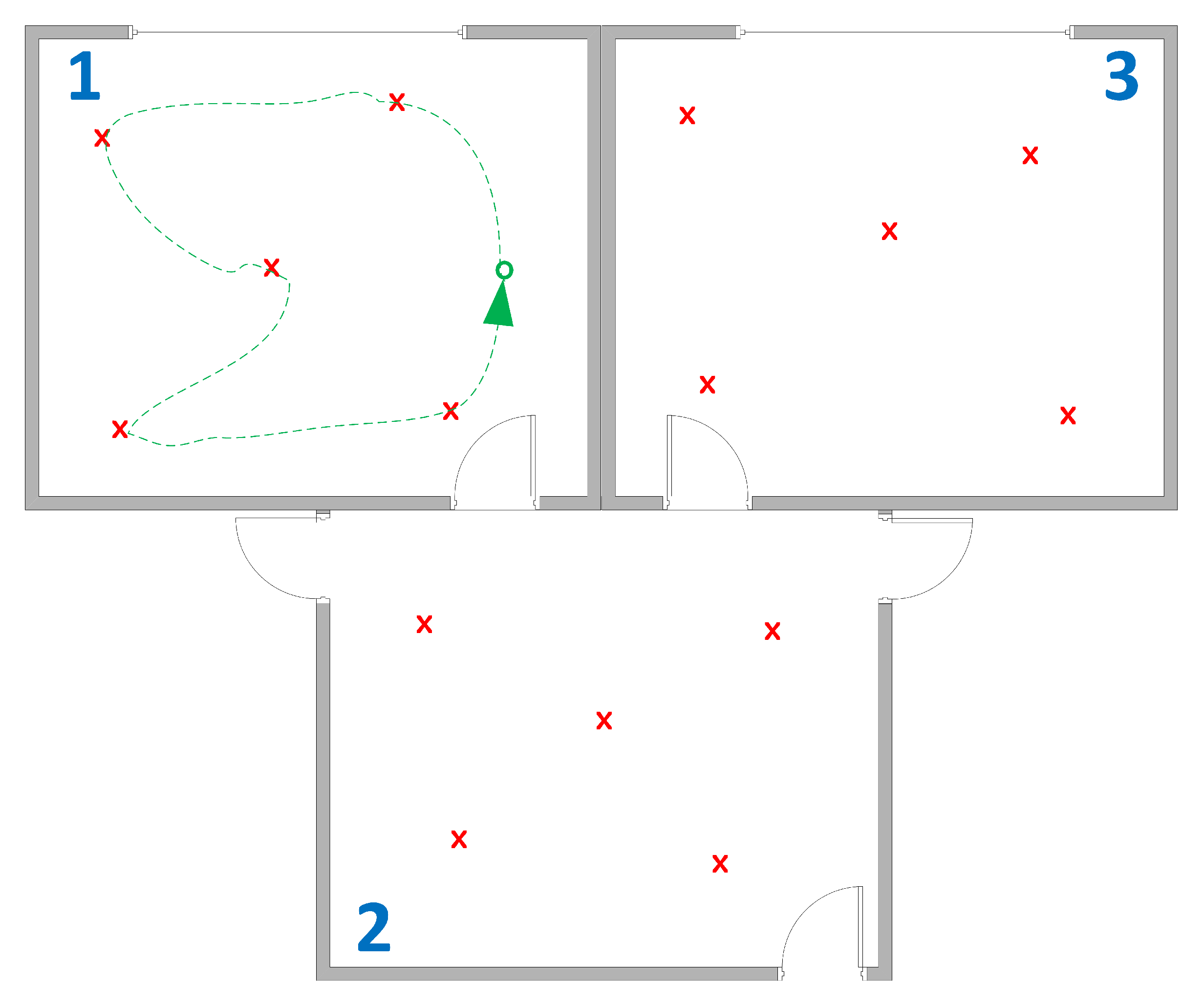
, the Access Point (identified by the Basic Service Set Identifier, BSSID) located in the vicinity of the robot, from which the robot could receive the beacon signals. Subsequently, the robot wanders teleoperated through a three-room scenario capturing Wi-Fi signals, BSSID with the received power as shown in the
Table 2. As this is supervised learning, a labeled dataset is required, so the room number is added to each sample.
During the experiment, the robot wandered through three rooms, staying in each room for about 12 min, collecting in total more than 4000 values from the access points and routers that were received in each room. Of this data, 70 percent will be used for supervised learning and the remaining 30 percent for model validation.
From a Machine Learning point of view, as we wanted to predict between various categories (which room the robot is in), we were faced with a multiclass classification problem. Therefore, a typical machine learning scenario was designed using Azure Machine Learning Studio, as shown in
Figure 16. The tool allows to graphically create various evaluation scenarios: from the data, collected from the robot’s Wi-Fi sensor, students can select the data columns and the project objective column, split the data for training and evaluation into a fraction, select the algorithm, carry out the training process, and finally score and evaluate the results. Therefore, students could easily apply and evaluate different parameters and machine learning algorithms, gaining insight from the results.
In particular, three supervised multiple classification algorithms have been evaluated to select the most appropriate: Multiclass Logistic Regression, Multiclass Decision Forest and Multiclass Neural Network.
Multiclass Logistic Regression classifier is based on the logistic regression method that predicts the probability of an outcome by fitting the data to a logistic function. A simple logistic regression model calculates the probability that an instance does or does not belong to a class using a sigmoid function applied to the linear combination of the input characteristics, resulting in linear decision boundaries. The training process is fast, as it only attempts to minimize a cost function based on the logarithmic of that probability. Multiclass Logistic Regression, also called Multinomial Logistic Regression or Softmax Regression, generalizes logistic regression for several classes. However, as the original binary classification method does, it defines linear decision limits, so despite its fast training, it is not very suitable for the problem under consideration, as can be seen from the resulting confusion matrix that is shown in
Figure 17. The training time was 17 s.
Multiclass Neural Network makes use of Neural Networks to perform the classification. A Neural Network is a set of interconnected layers made up of nodes. Each node receives as input the output of the nodes of the previous layer and generates as output a non-linear function of the weighted inputs. In this way, the first layer of the network is constituted by the inputs of the system and the last by the outputs. Between the two there may be one or more hidden layers. The number of hidden layers and nodes in each of them determines the capacity and complexity of the neural network. For example, deep neural networks [
43] present a high number of hidden layers for visual recognition, which is a complex task, although for tasks similar to those considered in this example, just one, or a small number, of hidden layers is generally sufficient. The learning is given by adjusting the weights that weight the inputs in the connections between each node in each layer, and this is done using a backpropagation algorithm. Therefore, the training time is usually high. Once the weights are set in the training, the output is predicted by propagating the values of the inputs through the layers.
Figure 18 shows the confusion matrix obtained with a Multiclass Neural Network classification algorithm on the dataset. The training time was 48 seconds using a Neural Network with a hidden layer, 500 nodes, 0.1 learning rate, and 1000 learning iterations. The results obtained show that do not allow an adequate generalization of the samples available. Thus, students can observe that using Neural Networks is not the solution in all cases, along with the black box perspective inherent in Neural Networks.
The last classification algorithm used is
Multiclass Decision Forest, which is based on the use of multiple decision trees. A decision tree learning algorithm creates a tree that goes from the observations on the features (represented in the branches) to a final classification (represented in the leaves). This tree is formed during the training process by recursively splitting the training set into two, trying to minimize impurity. The Multiclass Decision Forest is a generalized decision tree for several classes, but like the original, it defines non-linear decision limits, and it is resilient in the presence of noisy features. The algorithm builds multiple decision trees and then the probabilities of each output class are determined, weighting the output of each tree based on the calculation of label histograms and a normalization process. In this way, trees with high confidence in the prediction have greater weight in the decision. It is computationally fast, and allows to obtain good results with a little large quantity of data.
Figure 19 shows the confusion matrix obtained using eight decision trees, while
Figure 20 shows the eight trees generated by the algorithm. Training time was 22 s.
Therefore, students can observe that Multiclass Decision Forest is well suited for the example project, since the algorithm offers better performance with less training time.
Once the predictive model has been obtained, the next usual step in Machine Learning is the optimization of the results. Note that the prediction is made taking into account only two characteristics, the access point identifier (BSSID) and the received power, which can be very similar in different rooms. In this case, the goal will be to improve the dataset by adding new features that allow better classification performance. However, this process must be carried out with caution so as not to include too many feature that could generate very specific samples and limit the generalizability of the results in addition to increasing the risk of overfitting.
Thus, unlike other methods of Wi-Fi positioning based on Machine Learning, we will try to introduce an estimate of the distance to the starting point where the robot begins to prowl and collect data from the Wi-Fi sensor (green circle in
Figure 15), expanding the dataset with new features. In this way, for each point, we can calculate the correlation of beam powers received at the point to compare with the correlation of the beam powers received at the origin, using Pearson’s product-moment correlation:
where
is the mean of
X,
is the mean of the
Y values and n is the number of observations. To facilitate learning and interpretation, a scaling is performed based on the correlation coefficient that provides an estimate of distance in the range
(the lower the value, the greater the correlation and proximity):
In addition, we can also calculate the difference in the sum of powers of each access point at the current point and the origin. Both values could indicate an idea of distance to that defined origin. Furthermore, the number of new access points detected at the current point that were not detected at the origin, and the number of access points from the origin that remain at the current point, can be included as new features in the dataset as shown in
Table 3.
Figure 21 shows the new confusion matrix obtained by applying the Multiclass Decission Forest, again with 8 decision trees, but on the extended dataset. The training time was almost the same, 23 s.
The advantage of the new features can be seen in the new decision trees generated, much simpler (as shown in
Figure 22).
Figure 23 shows the second tree in detail, in which it can be observed that the new features are combined to facilitate classification, taking into account context information, while in the previous case the decision trees were based only on two features with particular information.
Azure Machine Learning Studio allows the creation of a Web service from the prediction model, which allows the model to be used by other robots in the same three-room environment. Thus, once trained, the predictive model was implemented as a service in the network, so that from the information offered by the topic
for a given location, the network service provides with a probability of location in rooms 1, 2 or 3, and this is given for each detected access point, as shown in
Figure 24. With this implementation of the service it is also possible to program a ROS node that subscribes to the topic beacon and determines in which room the robot is located.
The experiment is planned to be carried out in the classroom, so the performance of the system will degrade over time depending on environmental conditions, such as humidity or the presence or absence of people, as well as the appearance and disappearance of access points around the robot. In any case, the educational nature of the experiment should be taken into account, as an introduction to the use of Machine Learning in robotics for VET or undergraduate students. On the other hand, the method is promising and it would be desirable to explore performance with data obtained from long periods of time, so that a recursive procedure for continuous data capture and retraining could be implemented to avoid system degradation over time.
Beyond the results of the particular case, what this example shows is the use of Andruino-R2 as a valuable tool for the introduction to the study an application of machine learning in real scenarios for VET and undergraduate students.
7. Conclusions
Applied science requires testbeds and experimental setups to perform experiments and to validate the results of the application of the methods in practice. This is especially relevant from an educational point of view, since these types of tools can help in the teaching and learning of different techniques.
In this article, Andruino-R2, a new low-cost educational robot based on Arduino and Android, has been presented in detail and compared with the previous Andruino-A1. It is integrated with ROS, and allows the utilization of multiple sensors and communication resources: light sensors, ultrasonic sensors, GPS, camera, accelerometer, compass, Bluetooth, WiFi… The construction of the robot itself, together with its programming, provide learning outcomes in various areas. These sensors and resources can be applied in a simple way to carry out advanced tasks using real systems, but also maintaining the possibility of their integration with environments and simulation tools thanks to the 3D models developed.
In particular, the application of Andruino-R2 to learning and teaching in the fields of intelligent automatic control, computer vision and machine learning have been shown. Specifically, a practical application has been made to visual tracking of trajectories integrated with a Fuzzy Collision Risk system, which avoids collision with obstacles ahead. Likewise, a Wi-Fi positioning system has been presented, which allows identifying which room the robot is in, based on self-collected data and Machine Learning.
Therefore, Andruino-R2 is a valuable tool for education, research and innovation, but it maintains its simplicity, its low price and its open source. All in accordance with the educational policy “BYOR: Bring [Build] Your Own Robot”, which encourages every vocational or undergradute student to create or improve their own robots from scratch, and not just operate commercial robots or use simulation environments.


