Article

Behaviour of Steel Tubular Knee Joint in Aluminium Frames with Tension-Tie Element

1
Faculty of Civil Engineering, University of Zagreb, 10000 Zagreb, Croatia
2
Faculty of Mechanical Engineering and Naval Architecture, University of Zagreb, 10000 Zagreb, Croatia
3
Department of Structures for Engineering and Architecture, University of Naples “Federico II”, Piazzale Vincenzo Tecchio 80, 80125 Naples, Italy
*
Author to whom correspondence should be addressed.
Appl. Sci. 2021, 11(1), 70; https://doi.org/10.3390/app11010070
Submission received: 27 November 2020 / Revised: 18 December 2020 / Accepted: 19 December 2020 / Published: 23 December 2020
(This article belongs to the Section Civil Engineering)

Abstract

:

Featured Application

The conducted research is a fundamental step for gaining a better understanding of the behaviour of steel tubular knee joints in prefabricated aluminium halls. The conclusions made in this research can be applied for the development of reliable design methods of such joints and, consequently, wider application of aluminium halls.

Abstract

Aluminium portal frames with a tension tie element are a commonly used type of aluminium structure. Due to the significant reduction in aluminium’s mechanical properties caused by welding, typical beam to column joints of such frames are formed using bolts and welded steel knee joints embedded in the structure. Expressions for the reliable assessment of the behaviour of such joints are lacking, thus limiting the use of aluminium portal frames. Although the behaviour of steel joints using hollow sections is well investigated, there are only a small number of studies regarding knee joints, none of which investigate the influence of the tie element on the joint behaviour. Therefore, the first stage of the research is focused on the flexural behaviour of steel knee joints with tension tie elements. Laboratory tests of three identical steel knee joints with a tension tie element were conducted as well as a parametric numerical study with variation of tie element stiffness. It was concluded that different stiffnesses of the tie element have little influence on moment–rotation behaviour of the knee joint, but greatly affect overall frame resistance to vertical loads. It was also concluded that different stiffnesses of the tie element can lead to different failure modes of the knee joint as well.

1. Introduction

So far, aluminium structures have mostly been used in cases where the lowest possible weight of the structure and the longest durability are essential [1,2]. A typical example of the use of aluminium in civil engineering is for temporary roofing structures. Today, when sustainable construction is of utmost importance, there is an obvious need for aluminium application in permanent structures and, consequently, for reliable aluminium design methods [3]. Prefabricated aluminium halls are mostly designed as portal frames with added high-grade steel tension tie elements, where larger spans are required. Since welding in some types of aluminium alloy causes a significant reduction in resistance [4], typical joints of such structures are formed using bolts in combination with steel reinforcement embedded inside hollow aluminium sections. Such joints transfer the load partially through bolts and partially through a complex contact between the steel insert and aluminium tubes [3]. Expressions for reliable assessment of the behaviour for such joints are lacking, thus inhibiting the usage of aluminium prefabricated halls.
Although the behaviour of joints between steel hollow sections is generally well known, steel knee joints that are usually used in aluminium frames are not investigated as often. Wilkinson and Hancock conducted numerous tests to assess the ability of knee joints in portal frames to form plastic hinges [5,6,7]. Cold-formed rectangular hollow sections (RHS) made from steel grade C350 and C450 (nominal yield strength of 350 MPa and 450 MPa according to Australian Standard [8]) were used in tests. Experimental research included welded unstiffened and stiffened knee joints, end-plated bolted knee joints, and knee joints with a fabricated internal sleeve [7]. The joints were tested under both opening and closing moments. Knee joints under an opening moment failed at low rotational values, mostly by fracture in the heat-affected zone of the steel hollow section, while under a closing moment, web buckling was observed. Unstiffened and stiffened welded knee joints complied with the strength interaction requirements given in the CIDECT design guide for rectangular sections [9], but the joints were unsuitable for plastic design. Unstiffened joints were incapable of reaching the plastic moment both under opening and closing moments. Stiffened joints under an opening moment were also considered unsuitable for plastic design. Only stiffened joints under a closing moment were considered suitable to form plastic hinges, and only for steel grade C350. The bolted plate connection exhibited plasticity; however, the problem of weld failure in the heat-affected zone under tensile stresses was not fully overcome [7]. Joints with an internal sleeve sustained the plastic moment for large rotations, proving them to be suitable for plastic design. An additional benefit of the welded sleeve joint was the formation of the plastic hinge away from the junction of the two steel tubes [7].
Based on the research given in [5,6,7], Hancock [10] investigated the influence of a new welding-based solution on the rotation behaviour of stiffened steel knee joints under an opening moment. The solution implies the use of additional layers of weld on the flange in tension of a stiffened welded knee joint. The conducted research proved that the proposed welding-based solution allows for a significant increase in the rotation capacity of stiffened welded knee joints made from rectangular hollow sections.
The influence of bending moment and axial force interaction on the strength and stiffness of beam-to-beam and beam-to-column knee joints using component method extension was examined in [11,12] by Urbonas and Daniūnas. The obtained results show that tensile axial force reduces the stiffness of such joints. Tensile load equivalent to 10% and 25% of the joint load-bearing capacity can lead to stiffness reduction in the joint of up to 15% and 50%, respectively [11]. On the other hand, the results show that compression force increases the rigidity of such joints.
The behaviour of knee joints in portal frame sheds made of cold-formed C-channels was investigated by Mills, J. E. [13]. Such structures have been broadly used in Australia and New Zealand. Nevertheless, in many cases, designs of cold-formed C-channel section knee joints were taken from hot-rolled portal frame designs given in Australian design codes [14]. Such a design approach is incorrect, since the sections being connected are obviously different in nature. According to the conducted research, knee joints in portal frames made of cold-formed C-channel sections fail prematurely as they are not able to achieve the moment capacity of the connected sections. Various alternative knee joint designs using cold formed channel sections were proposed and constructed, but testing showed [13] that many of these are also unable to meet required capacities under test.
The current European norm for the design of joints in steel structures [15] gives a design procedure for stiffened and unstiffened welded knee joints subjected to bending and axial force but without the tension tie element. A similar design method can be found in CIDECT design guide [16]; however, it is questionable whether method is applicable to knee joints with a tie element, a solution that is quite often used for aluminium portal frames.
The aim of this research is to provide deeper insight into the behaviour of such joints and consequently the future development of effective expressions for their reliable and quick design. In the first stage of the research, a series of laboratory tests were conducted on steel knee inserts with a tie element. Additional parametric numerical studies provided insight into the effect of tie element stiffness on the bending resistance, rotation capacity and failure modes of analysed steel knee joints.

2. Experimental Program

2.1. Scope

Laboratory testing was conducted at the Faculty of Civil Engineering, University of Zagreb. Three identical steel knee joints (marked with S1–S3) were tested under static loading to induce bending in the specimens. At both ends, specimens were supported with pin connection to allow free rotation around one horizontal axis while restraining translation in all directions (Figure 1). However, translation in the vertical direction was allowed at the free end of the beam element using roller type support to enable the introduction of the load. At the initial position, the angle between the tie element and the beam was 15°, which corresponds with the geometry of realistic prefabricated aluminium halls.

2.2. Geometrical Properties

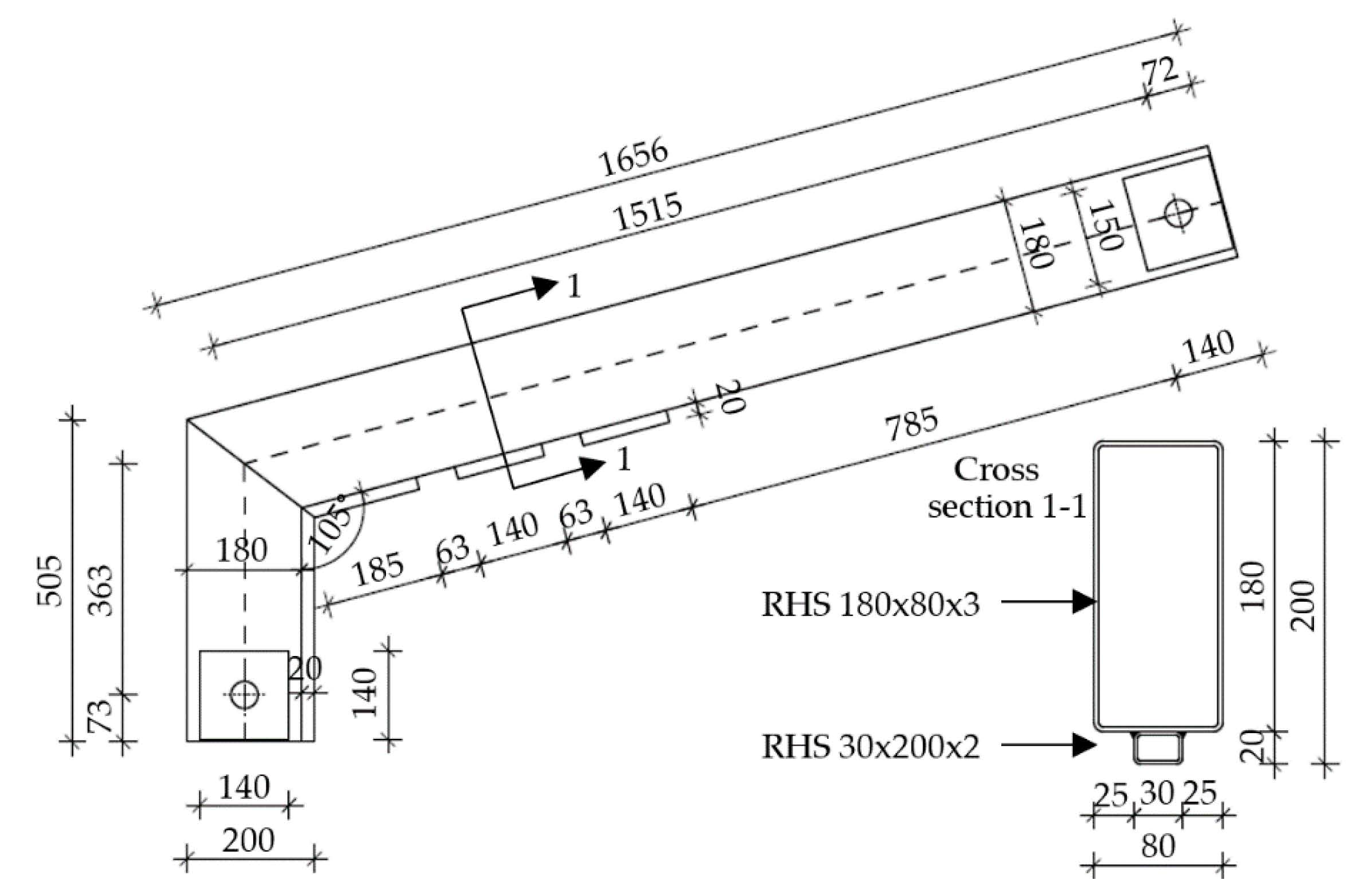
The geometry of the steel joint (insert in aluminium portal frame) was selected to simulate the realistic situation occurring in the prefabricated aluminium frame, which is usually built by using a rectangular aluminium profile 230 × 90 × 3 mm with slots. Thus, the geometry of steel insert was determined with the size of the aluminium cross section. The insert was formed using butt-welded hollow sections RHS 180 × 80 × 3 mm, forming an angle of 105°. Additionally, a smaller tube RHS 30 × 20 × 2 mm was butt-welded on the inner side of the steel knee insert as reinforcement (Figure 2).
For aluminium portal frames with spans greater than 10 m, a high-strength steel tension tie element (typically Ø 16, 6 × 37-FC, 1770 MPa (EN 12385-1 [17])) is used. However, due to the requirements of the strain measurement, a tie element with a circular hollow section (CHS) 100 × 4.75 (S 235 JRH) was selected (Figure 2). The tie element is connected to the beam by a T-adapter with two M20, 8.8 quality grade bolts, which are attached to nuts that are welded to the previously drilled holes on the lower flange of steel insert beam part [3]. On the other side, the tie element was connected to the rigid supporting structure using a similar T-adapter and a pair of M20, 8.8 quality grade bolts. That kind of setup allowed the steel tube to rotate freely around two horizontal axes (pins), thus only axial forces could occur.

2.3. Mechanical Properties of Base Material and Welds

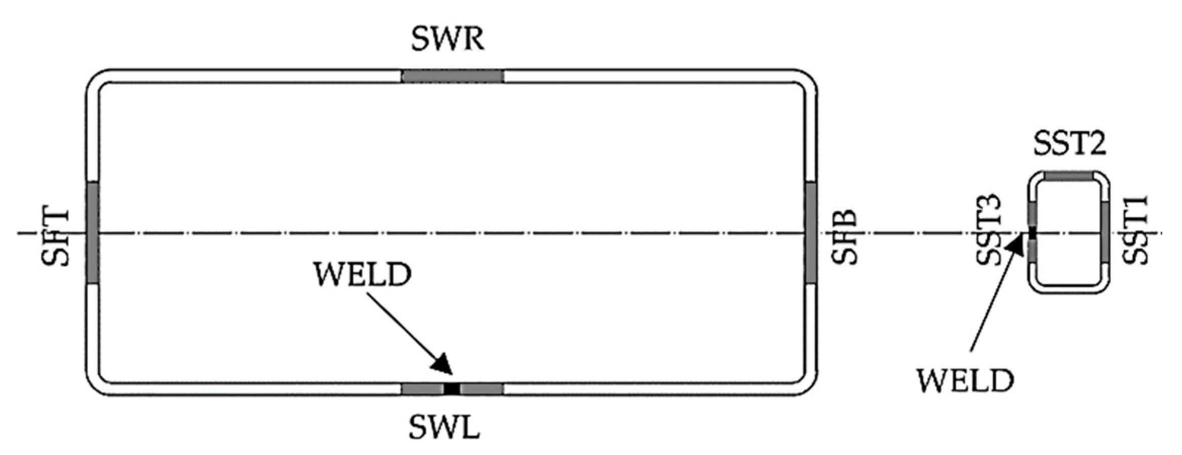
To determine the material properties of the base material, a series of 15 coupon tensile tests were performed according to ISO 6892-1:2019 [18] on universal testing machine Zwick/Roell Z600E. Coupons were divided into two groups: 12 coupons taken from RHS 180 × 80 × 3, and the remaining 3 coupons taken from smaller RHS 30 × 20 × 2, as shown in Figure 3. SWR and SWL stand for steel web right and steel web left, respectively, while SFT and SFB stand for steel flange top and steel web bottom, respectively. Similarly, SST stands for smaller steel tube. All the steel elements were made from structural steel S235 JRH [19]. No coupons were taken from the tie element CHS 100 × 4.75.
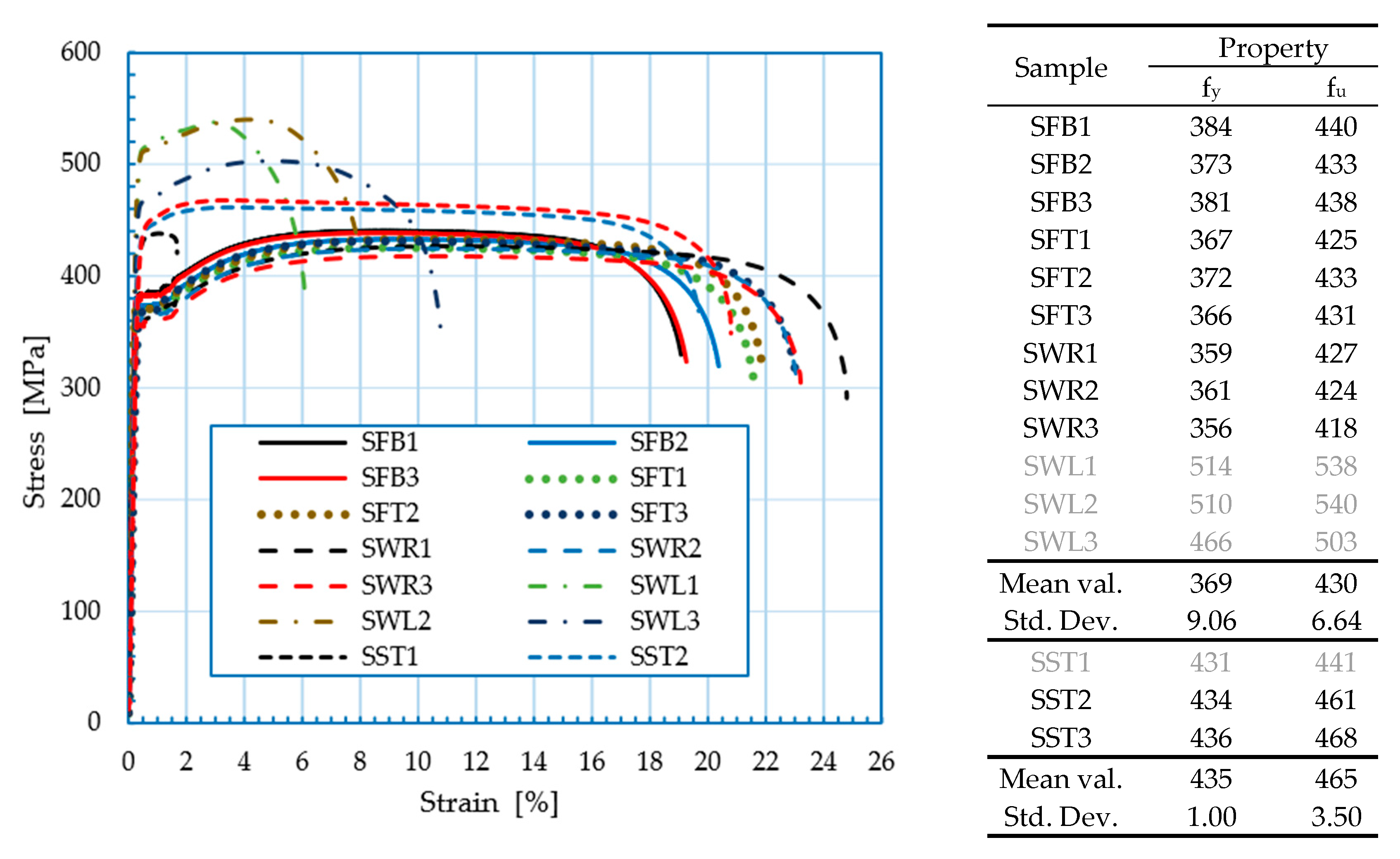
The mechanical properties of RHS 180 × 80 × 3 were characterised by stress-strain curves taken from 12 coupons (Figure 4). Deviation of the results for the curves SWL1–SWL3 can be noted. Those coupons showed higher yield and ultimate strength but brittle behaviour as well. Such results are expected, since coupons for SWL were taken from the welded part of the cross section. Hence, those results were not taken into consideration when calculating mean values of mechanical properties for the RHS 180 × 80 × 3 for the purpose of numerical study. The mean value of yield strength (fy) was 369 MPa, with a standard deviation of 9.06 MPa. The mean value of ultimate tensile strength (fu) was 430 MPa, with a standard deviation of 6.64 MPa. It can be noted that values of fu of 9 tested samples show lower scatter compared to values of fy (6.64 < 9.06).
Mechanical properties of RHS 30 × 20 × 2 used as reinforcement are characterised by stress–strain curves SST1-SST3 (Figure 4). Deviation can also be noted for the SST1 coupon which was taken from the welded part of the smaller steel section RHS 30 × 20 × 2. That coupon failed prematurely as well; therefore, that result was omitted when calculating mean values of fy and fu for the smaller steel section. The mean value of fy was 435 MPa, with a standard deviation of 1.00 MPa. The mean value of fu was 465 MPa, with a standard deviation of 3.50 MPa. Although they are made from nominally the same steel grade, it can be noted that steel coupons taken from the smaller RHS 30 × 20 × 2 section show higher values of fy and fu strength but lower ductility. That kind of behaviour can be contributed to the higher effect of the residual stresses in the cross section introduced by welding and the cold forming process of the smaller tube.
Detailed testing of butt welds between the beam and the column (Figure 5) was conducted at the Faculty of Mechanical Engineering and Naval Architecture, University of Zagreb. The welding process MAG 135-D was used. It must be noted that test specimens were chosen by random sampling and they represent standard quality and work in the practice of the steelwork manufacturer.
Based on the visual quality testing, welds are classified as category D (lowest quality of weld according to EN ISO 5817:2014, [20]) because of the uneven geometry, spatter on the base material and poor start-stop performance. Dye penetrant testing gave insights into the local lack of fusion and sagging, mostly around the weld transition from the butt weld to the corner weld and the start-stop area. The presence of cracks was not found.
Macrograph analysis showed incomplete penetration with approx. 2–2.5 mm of weld reinforcement. Bending of the face and the root of the weld (to an angle of 180°) did not reveal irregularities in the metal of the weld or the heat affected zone (HAZ). Due to the very small and incomplete penetration of approx. 0.5 mm, a static tension test of the entire section, including the reinforcement of the weld, was performed. The results show that the failure occurs in the base material, outside of the HAZ. It must be noted that the strength of the base material is lower compared to that of the consumable material (wire).

2.4. Loading Protocol and Measurements

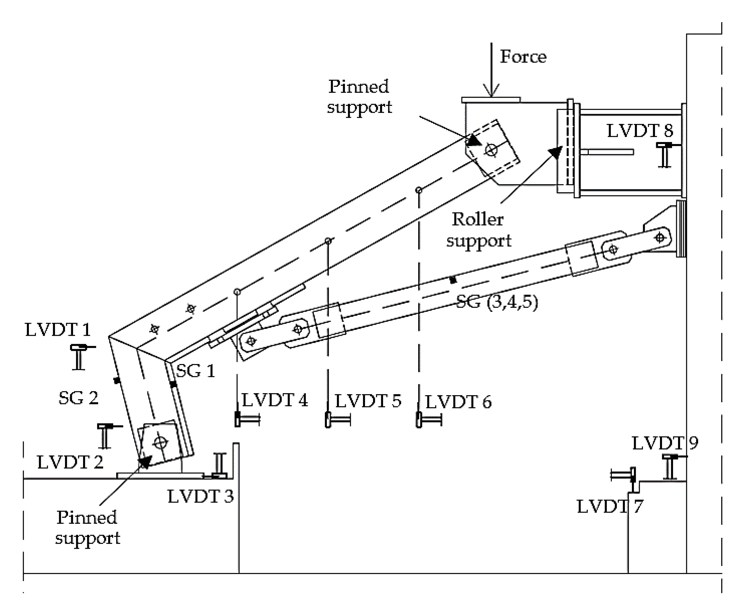
Displacements of the specimens were measured using linear variable differential transformer (LVDT) sensors, while deformations were measured using strain gauges (SG) [21]. For each sample, nine LVDT sensors were used (LVDT1 to LVDT9) and five strain gauges (SG1 to SG5) (Figure 6). Rotation of the column was measured using LVDT 1 and LVDT 2, while the horizontal displacement of the column base was measured using LVDT 3. Vertical displacements of the beam were measured with LVDT 4–LVDT 6. Displacements of the supporting structure measured using LVDT 7–LVDT 9 were smaller than 1 mm, leading to the conclusion that no significant rotation of the supporting structure occurred during all tests.
Strain gauges SG1 and SG2 measured relative deformations on inner and on outer column flange to obtain the stress state of the column. In the middle cross section of the tie element, three strain gauges (SG3 to SG5) were radially placed, forming an angle of 120°, to determine the value of deformations and subsequently the axial force in the tie element.
The same loading regime was applied for all the tested specimens. The testing of steel knee joints was carried out on universal tensile-compression testing machine 600/250 with the capacity of 600 kN and maximum piston movement of 250 mm powered with a 55 kW hydraulic pump. The loading procedure was carried out in three phases: (i) loading up to 20 kN, (ii) unloading, and (iii) stepwise loading up to the failure [3]. Displacement controlled loading was applied with constant speed of 1.2 mm/min. In the third phase, the load increment was 10 kN in the elastic range. As the load value progressed to the plastic range, load increment was limited to a piston displacement of 6 mm, as the load increment of 10 kN could not be maintained. Each phase was followed by a 2-min pause with the constant load value [22].

2.5. Experimental Results

2.5.1. Load–Displacement Relationship

The overall behaviour of all specimens is characterised by the load–displacement curves given in Figure 7, where the steel joints are marked with S1–S3. The displacements were recorded in the piston. Small drops can be spotted in the load–displacement curves due to the incremental increase in the load value. During every pause in the loading process, slight relaxation in the specimens occurred since loading was displacement-controlled and not force-controlled. It can be concluded that specimens S1 and S2 behaved similarly, while specimen S3 had a softer response after reaching 53 kN. This behaviour can be explained by the premature failure of the weld between the tensile bolt nut and the steel knee joint [3].
The curves shown in Figure 7 are characterised in Table 1, where Fpl and Δpl stand for plastic resistance and the corresponding deformation of the joint, while Fu and Δu stand for ultimate resistance and ultimate deformation, respectively. The plastic resistance of the joint and the corresponding deformation are defined as values at the intersection between regression lines of the elastic and plastic region of the load–displacement curve (see methodology explained in Section 2.5.2).
It can be seen from Table 1 that the mean value of Fpl is equal to 59.0 kN, while the mean value of Fu is equal to 80.9 kN. It is also visible that measured values of Fpl are less scattered than those of Fu (4.55 < 5.86). Furthermore, the mean value of Δpl is 11.2 mm, while the mean value of Δu is 28.5 mm. The values of Δpl are significantly less scattered in comparison to the values of Δu (1.43 < 3.49).

2.5.2. Moment–Rotation Relationship

To characterise the flexural behaviour of the tested steel knee joints, bending moments versus rotational deformations curves, i.e., the Mj–ϕj curves, were obtained, using primary test results and common rules to obtain equilibrium on the undeformed element, Equations (1)–(5). Having obtained force at the piston (FP) and force in the tie element (FT) from the test, the horizontal reaction at the beam end (RH,P) can be calculated using known geometry (Figure 8) and consequently, first order bending moment at the beam to column intersection Mj can be expressed as follows:
M j   =   739   R H , P 1323   F P + ( 185   cos ( 14.17 ° )     ( 89 + 248 )   sin ( 14.17 ° ) )   F T
M j   =   487   F P     271   F T
Note that dimensions in Equations (1) and (2) are in mm, therefore, the results of bending moment will be expressed in kNmm if forces are entered in kN. Generally, rotation at the knee joint ϕj can be calculated as subtraction of the beam rotation (ϕb) and the column rotation (ϕc):
ϕ j   =   ϕ c     ϕ b
Assuming that the column and the beam remain undeformed due to external loads and all the deformation is concentrated in the beam–column intersection (Figure 8), rotation of the beam (ϕb) and of the column (ϕc) can be calculated using the following expressions:
ϕ b = tan 1 [ 561     352   +   tan ( 14.17 ° )   δ 1     δ 4 375   +   δ 1 ] 29.17 °
ϕ c   =   tan 1 [ δ 1 352 ]
where δ1 and δ4 are displacements in mm measured at LVDT1 and LVDT4, respectively. The angle of 14.17° represents the deviation of the column from verticality (see Figure 8). It must be noted that for the arbitrary displacement of the piston, Equation (4) will give negative values of ϕb, while Equation (5) will give positive values of ϕc. Such an approach was chosen since arbitrary displacement of the piston will lead to a mutually opposite direction of rotation of the beam relative to the column.
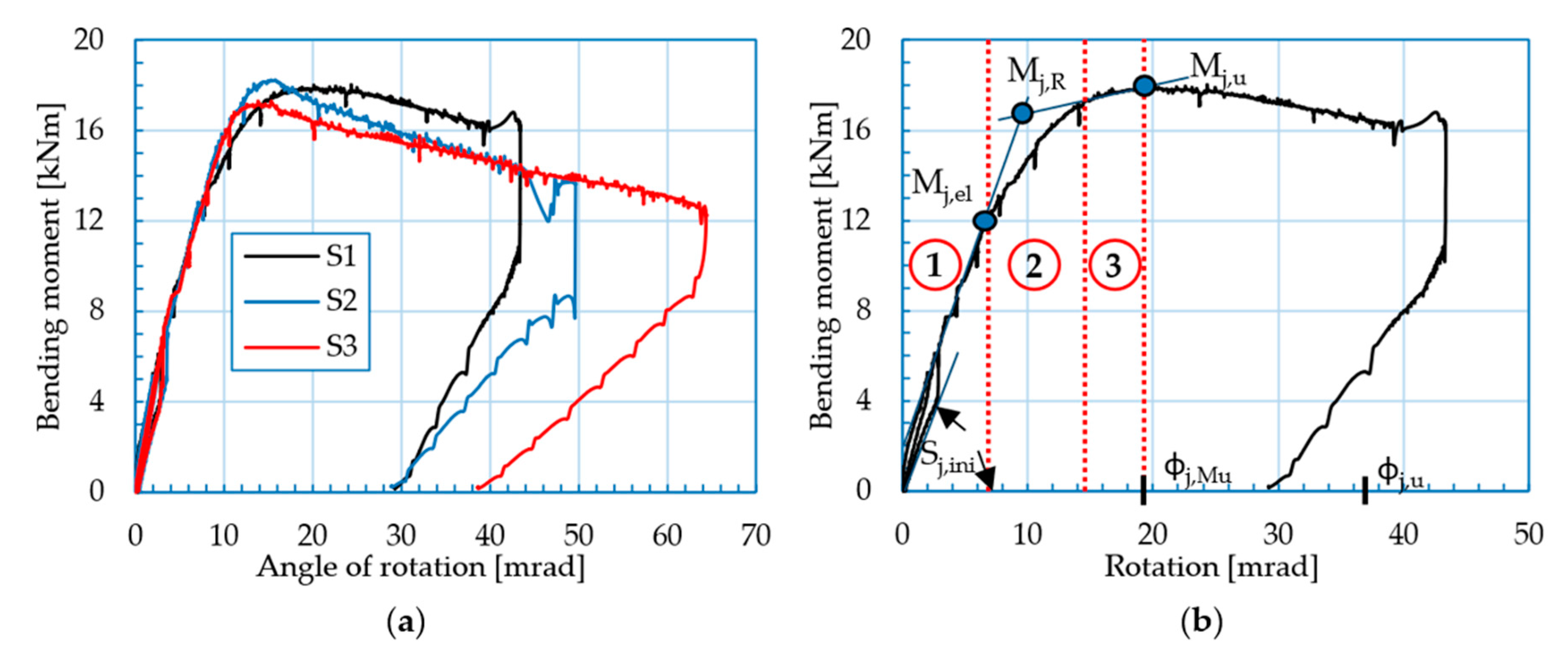
Bending moment versus rotational deformation curves are shown in Figure 9. It is visible that these curves consist of three characteristic regions: the elastic (linear) region (marked as 1), the knee-range (marked as 2), and the postcritical region (marked as 3) (Figure 9b). The bending moment that characterises the resistance of the steel joint Mj,R is defined at the intersection of the secants of the elastic and small postcritical region (after knee-range and before ultimate moment) (Figure 9b). The initial rotational stiffness is defined as the slope of the downward curve in the first loading phase (Figure 9b).
As can be seen from Figure 9a, all the specimens showed relatively similar rotational properties. The main properties of Mj–ϕj curves are given in Table 2. The lowest bending resistance Mj,R was obtained for specimen S3, amounting to 16.6 kNm, while specimens S1 and S2 had slightly higher values of bending resistance Mj,R (17.1 and 17.6 kNm, respectively). The lowest value of elastic bending moment Mj,el was measured for specimen S1, amounting to 12.4 kNm. Specimen S3 had a 10% (13.7/12.4) higher value of elastic moment compared to specimen S1, while specimen S2 had a 20% (14.9/12.4) greater value of elastic moment compared to specimen S1. The elastic bending moment Mj,el showed greater variation of values compared to bending resistance Mj,R (1.02 > 0.408).
The maximum value of the ultimate bending moment Mj,u was achieved for specimen S2, amounting to 18.2 kNm, with corresponding rotation of 15.4 mrad. On the other hand, the minimum value of the ultimate bending moment was achieved for specimen S3, amounting to 17.2 kNm, with corresponding rotation of 13.9 mrad. Specimen S1 failed at the value of ultimate bending moment of 17.9 kNm and a corresponding rotation of 19.9 mrad. It can be noted that specimen S1 showed significantly higher rotational deformation prior to reaching maximum bending moment.
In terms of the initial rotational stiffness Sj,ini, all the specimens showed similar behaviour. Specimen S2 had the highest initial rotational stiffness of 1663 kNm/rad, followed by specimen S1, with the value of initial rotational stiffness of 1641 kNm/rad. Specimen S3 had the lowest initial rotational stiffness of 1541 kNm/rad.
On the other hand, specimen S1 had the lowest ultimate rotational deformation ϕj,u, amounting to 39.2 mrad while the specimen S3 showed the highest ultimate rotational deformation of 63.3 mrad. Specimen S2 had ultimate rotational deformation of 43.9 mrad. It must be noted that specimen S3, which had the softest response compared to specimens S1 and S2, also had by far the highest value of ultimate rotational deformation.

2.5.3. Failure Modes

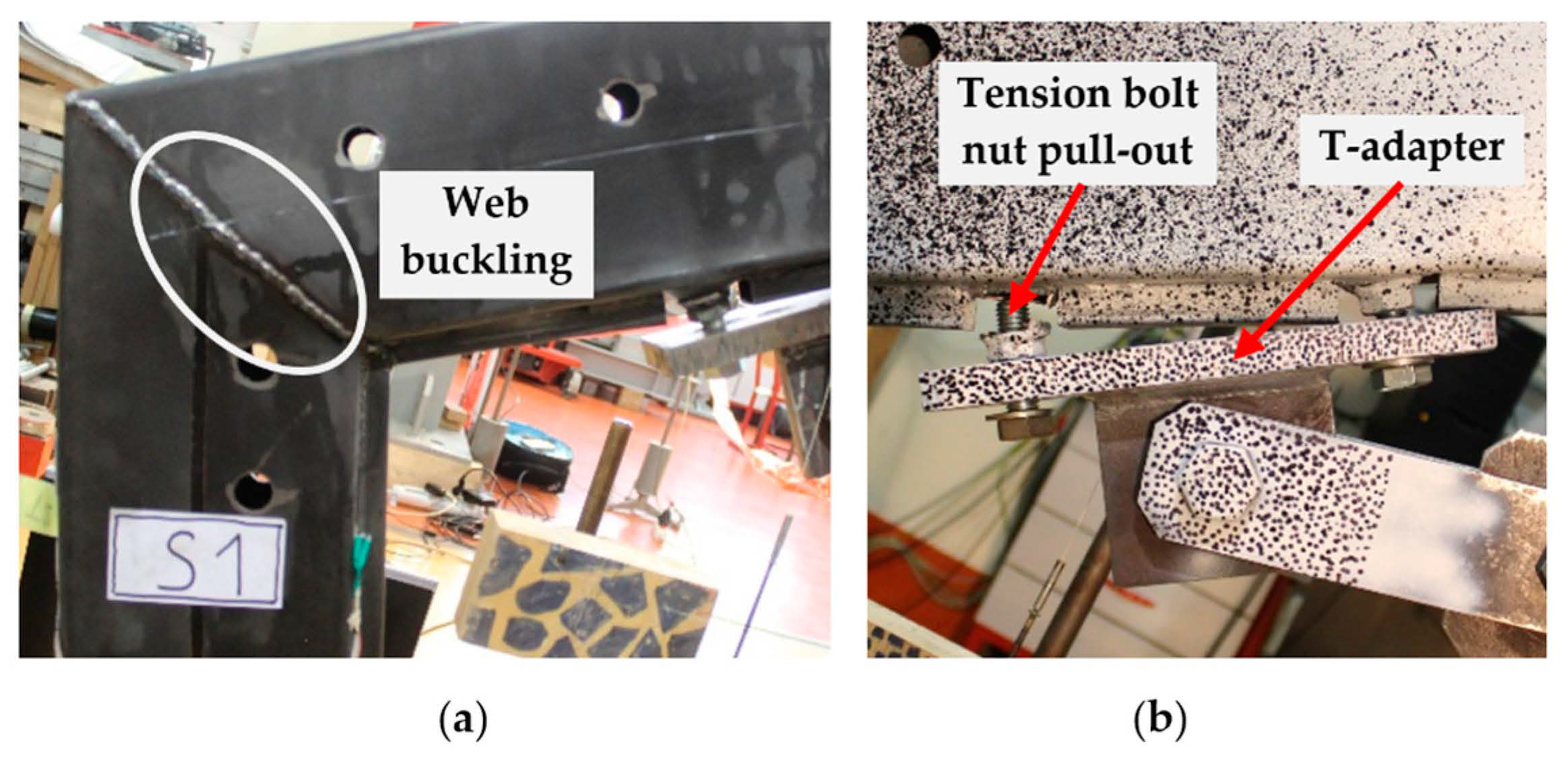
All of the steel specimens failed in a similar mode. In the beginning phase of loading, slight buckling in the compression zone of the joint can be noticed (Figure 10a). A further increase in the load causes the activation of the tie element, i.e., tension in the tie element occurs, restraining further buckling of the joint in the compression zone. As the load increases even more, tension in the tie element increases, causing rotation of the T-adapter of the tie element. Rotation of the T-adapter causes compression in the knee joint on one side of the adapter and tension in the bolt on the other. The joint fails when the end weld between the tensile bolt nut and the steel knee joint fails, Figure 10b.

2.5.4. Force in the Piston-Tension in tie Element Relationship

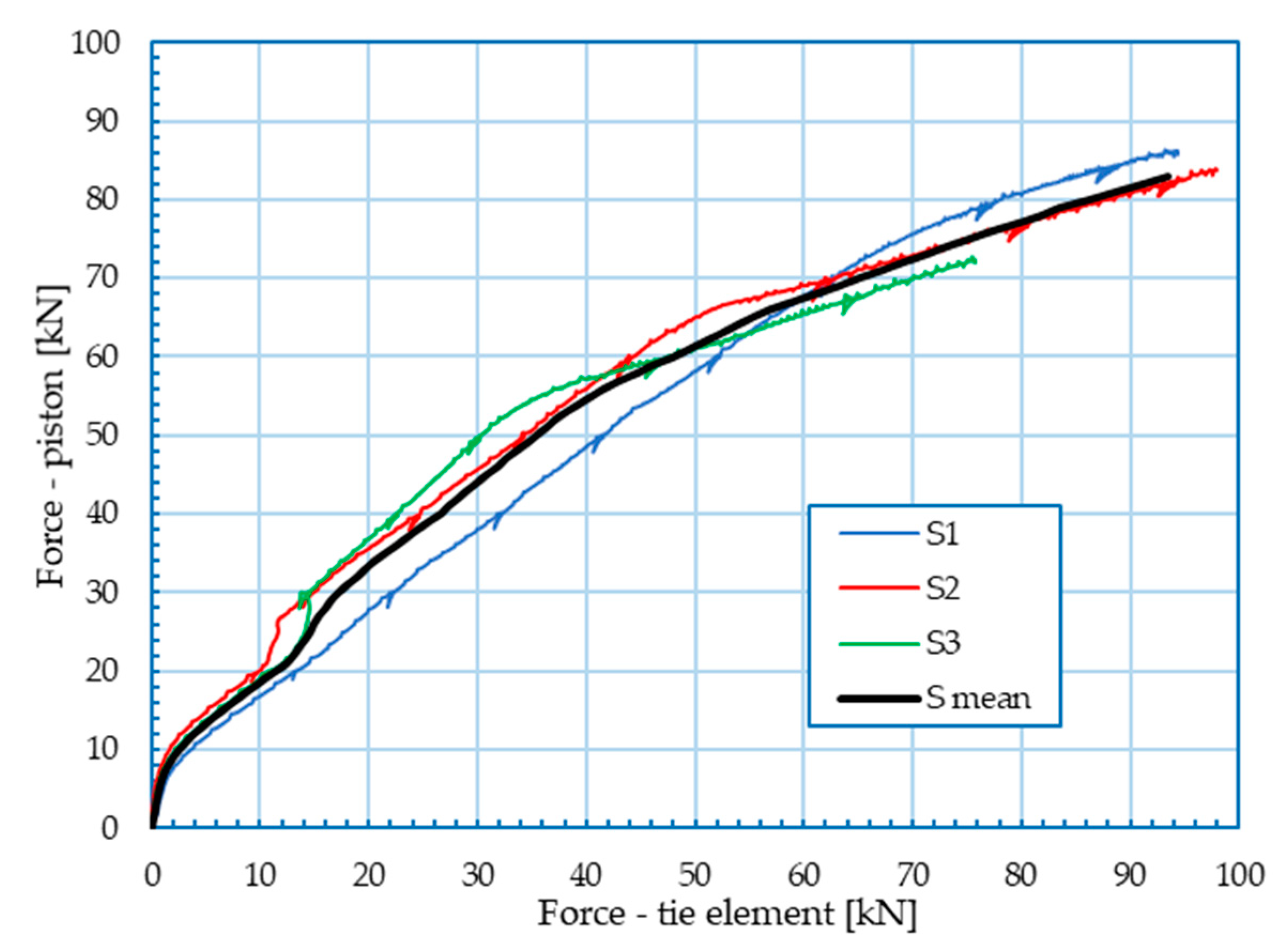
Strain in the tie element was recorded by three strain gauges (SG 3–SG 5) in the middle cross section of the tie element in all 3 specimens (S1–S3). Using the calculated mean strain value of the tie element, tensile force in the tie element was calculated for each specimen, and subsequently, the relationships of the load at the piston and the force in the tie element was obtained (see Figure 11). The mean value of tensile force in the tie element for specimens S1–S3 was also calculated. After reaching a force at the piston of approx. 72 kN, specimen S3 failed. Due to the premature failure of specimen S3, tensile force in the tie element for that specimen had to be extrapolated so that average value could be calculated for the entire range (black curve).
As expected, an increase in the force in the piston leads to an increase in the load in the tie element. Jumps in the force in the piston-force in tie element curves are visible around 20 kN force in the piston (Figure 11), and they are caused by slippage of the bolts between the tie element and the knee joint. Maximum tensile force in the tie element was approx. 86 kN for the specimen S1. On the other hand, resistance of the tie element cross section to axial tensile force was approx. 340 kN for the measured cross section surface area and fy = 235 MPa. Therefore, it can be concluded that tie element was not even close to reaching the yield strength, i.e., that its behaviour was deeply in the elastic range during all tests.

3. Numerical Analysis

3.1. General Overview of the Numerical Model

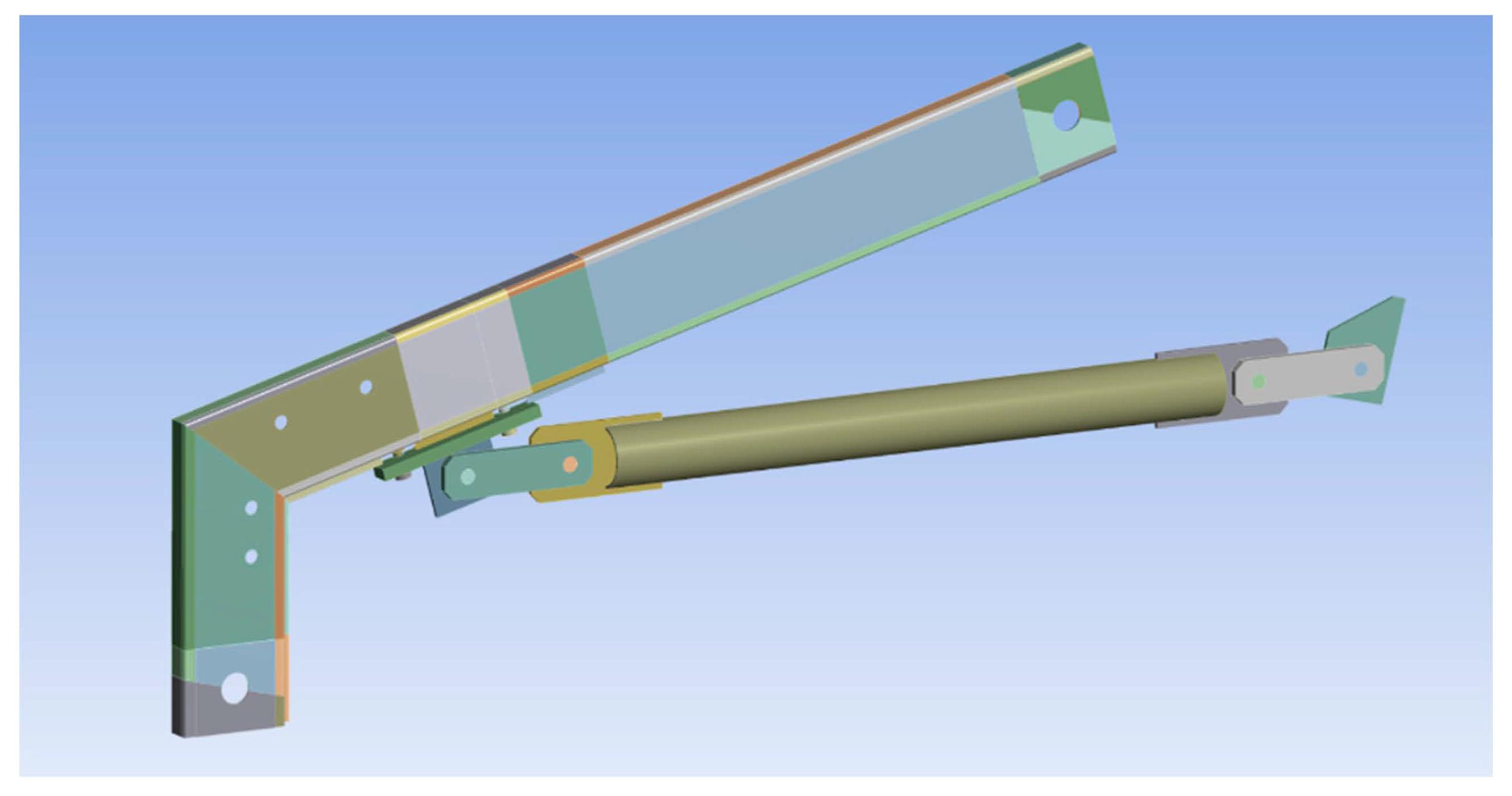
Numerical modelling was conducted in software package ANSYS 17.0 [23]. Geometrical properties of the numerical model were determined according to laboratory measurements to achieve more realistic behaviour. Thicknesses of the steel tube sections were determined as an average of measured values [22]. To apply different material properties to various parts of the numerical model and to generate more precise mesh, the numerical model was divided into several geometrical parts (Figure 12). Only solid finite elements were used in the analysis, both tetrahedral and hexagonal. Finite element size in the model was 7.5 mm, which was enough to achieve mesh convergence. In the contact regions, mesh was refined to 2.5 mm element size to achieve more accurate results.
Nonlinear behaviour of the base material was included using multilinear stress–strain curves analogous to those obtained by coupon tensile tests, Figure 4. All the stress–strain curves were transformed into true stress–strain curves by common rules to achieve more accurate results. It must be noted that no tensile tests were performed for the tie element; therefore, to model the behaviour of the tie element, the same mechanical properties were used as for the RHS 180 × 80 × 3 element. Since no plastic deformations of the tie element were recorded during laboratory tests, such simplification had a negligible effect on the overall behaviour of the steel specimen. Nonlinear behaviour of the bolts was included using a multilinear stress–strain curve. Since bolts were not tested, nominal strength values for the 8.8 quality bolt class were used. Prior to reaching a bolt yield strength of 640 MPa, material behaviour was modelled as linear elastic with E = 2 × 10⁵ MPa. The ultimate strength of 800 MPa corresponds to plastic deformation of 1%, followed by a plateau region up to an ultimate deformation of 2%.
Initial geometrical imperfection of the steel specimen around the butt-welded connection was included in numerical models as well. To prevent the penetration in the contact region between the two parts of the model, contact interaction between the surfaces was defined or the addition of the contact elements was introduced. Numerical modelling was conducted using three-dimensional solid elements only. To reduce the number of finite elements in the model and to shorten the calculation time, symmetry around the vertical plane was used [21].
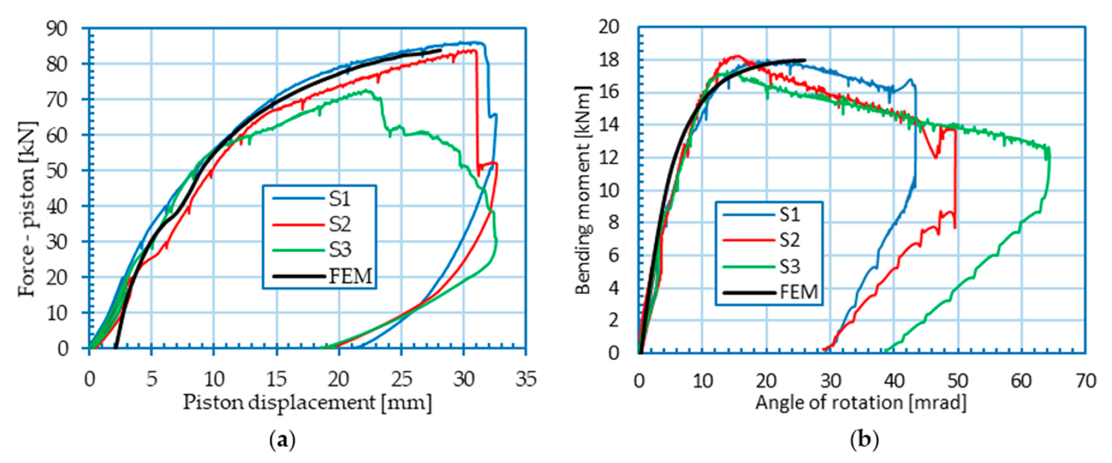
Boundary conditions in the numerical model were defined to represent those of the laboratory test as accurately as possible. At both ends, the steel specimen was free to rotate around the horizontal axis while translations at both ends were restricted in all directions except for vertical displacement at the free end of the beam to allow the introduction of the load in the specimen in the form of a 30 mm vertical displacement. It must be noted that 2 mm displacement of the supporting structure in the horizontal direction occurred during the loading phase, which corresponds to approx. 2 mm displacement in the vertical direction at the piston. That was included in the numerical results as 2 mm translation of the numerically obtained force–piston displacement curve (Figure 13a). All the boundary conditions in the model were assigned on the perimeter of the pin hole.
Loading of the steel specimen was modelled in two steps. Prestressing of the bolts to a value of 10 kN that corresponds to manual tightening of the bolts as well as out of plane line pressure of 40 N/mm at the line of the web welds to represent initial deformations in the HAZ were modelled in the first load step. Linearly increasing displacement of 30 mm in the vertical direction at the free column end was modelled in the second loading step.

3.2. Simulation of Performed Tests

Comparison of experimental and numerical results is given in the form of piston force–piston displacement curves (Figure 13a). It can be observed that experimental results coincide well with the numerical simulations, confirming the correctness of the calibration procedure. However, numerical models displayed higher stiffness in the beginning of the loading compared to experimental results. The reason for that kind of deviation is the inactivity of the tension tie element in the beginning of tests, while in the numerical model, the tie element is active from the beginning of the loading phase [21]. Good matching between experimental and numerical results in the form of bending moment–rotation of joint (Mj–ϕj) curves is also obtained (Figure 13b).
In Figure 14, a graphical comparison between the failure mode obtained in the laboratory specimen and by numerical analysis is given. The numerical model gave a similar response regarding failure behaviour. In both experimental and numerical analyses, tensile bolt nut pull-out was the cause of failure in conjunction with the rotation of the T-adapter and buckling of the web on the beam to column joint.

3.3. Numerical Parametric Analysis

For prefabricated aluminium halls with spans greater than 10 m, a high-strength steel tension tie element is used (commonly Ø 16, 6 × 37+FC, 1770 MPa [17]) to reduce bending in the knee and to allow for greater spans. Due to the limitations of the laboratory equipment, the circular tube CHS 100 × 4.75 (S 235 JRH) was selected, resulting in much stiffer overall behaviour of the steel knee joints subjected to bending compared to one in a real structure, when high-strength wire rope would be used. That kind of behaviour can be contributed to three reasons:
  • The cross-sectional area of the tie element used in the laboratory testing is 14.2 cm2, which is much higher compared to that of a high-strength steel wire rope that is equal to 1.10 cm2 for commonly used Ø 16, 6 × 37 FC steel wire rope.
  • Due to spatial limitations of the laboratory equipment, the length of the tie element was approx. 1 m, which is much shorter compared to real aluminium portal frames with a tie element (usually spanning between 10 and 20 m).
  • High strength steel wire ropes in general have a lower modulus of elasticity compared to that of a structural steel. The modulus of elasticity for various types of steel wire ropes with fibre core can vary in the range from 68.7 to 98.1 GPa according to [24]. For this numerical analysis, a modulus of elasticity of 80 GPa was chosen and implemented.
To investigate the influence of the tie element stiffness on the behaviour of the steel knee joint, numerical analyses were conducted, varying the stiffness of the tie element. Since the geometry of the steel wire rope is very complex, a simplification was made in the numerical model where the geometry of the specimen was left unchanged (Figure 12), but the modulus of elasticity of the tie element was reduced by the nondimensional factor, fred, which represents the stiffness ratio of the tie element used in the laboratory test and the tie element used in practice. Taking into consideration the difference in cross-sectional area, modulus of elasticity and the length of the tie element between the laboratory specimen and real structure, the reduction factor, fred, can be defined with the following expression:
f red     17.2   L ,
where L represents the span of the portal frame in meters. Six different spans where taken into consideration ranging from 1 to 20 m (Table 3). Considering that the common span of the aluminium portal frames with the tie element ranges between 10 and 20 m, 5-, 2.5- and 1-m spans were considered for academic purposes only. A knee joint without the tie element was considered as well. In Table 3, reduction factors fred along with their corresponding reduced modulus of elasticity are given for the considered span values.

3.4. Discussion of Parametric Numerical Analysis Results

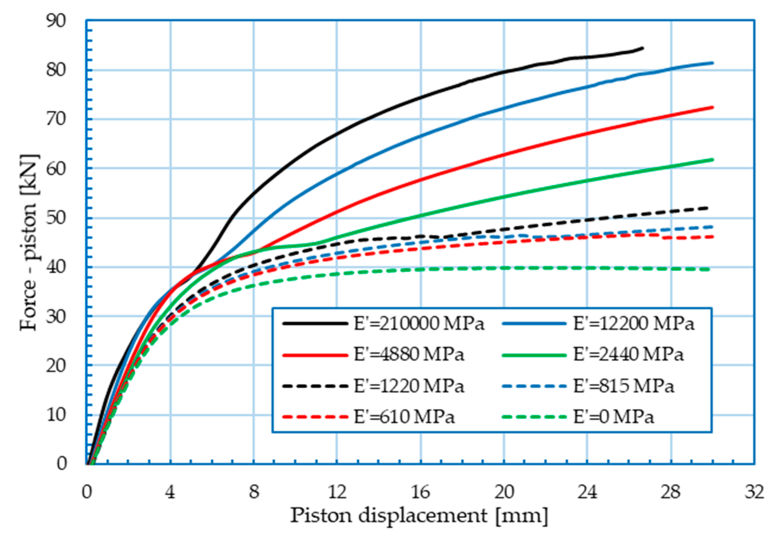
The results of the numerical analyses are presented in Figure 15 and Figure 16. Force–piston displacement curves for different tie element stiffnesses are shown in Figure 15. The increase in the tie element stiffness increases the maximal piston force (load) significantly. In the elastic region, the behaviour of the knee joint is relatively similar for all analysed cases. In the knee range, and especially in the postcritical region, the influence of the tie element stiffness is much more pronounced. In the case of knee joints with a softer tie element (dashed curves), differences in the force–piston displacement curves in the postcritical region are less pronounced.
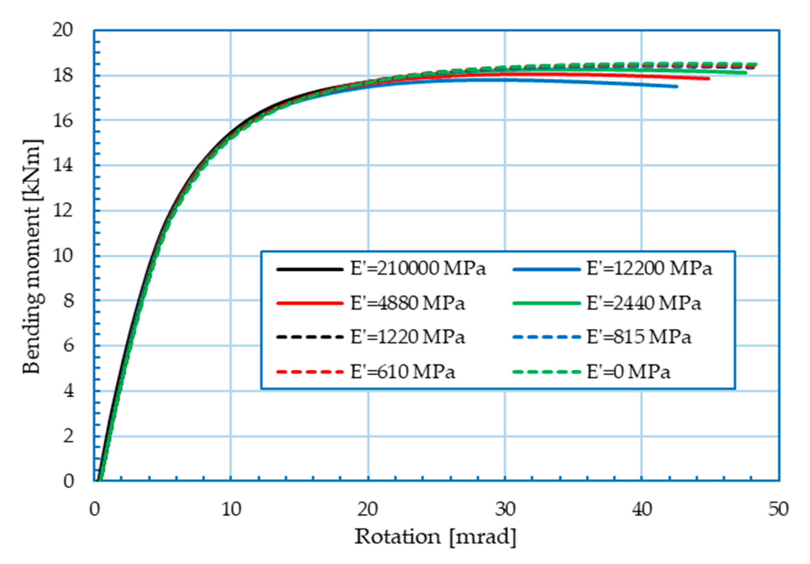
Figure 16 represents the moment–rotation relationship of the analysed knee joints where both moment and rotation were measured at the beam to column intersection of the knee joint using Equations (1)–(5). It can be seen from the Figure 16 that stiffness of the tie element has a negligible effect on the moment–rotation relationship of the knee joint. In the elastic range, the moment–rotation relationship of the knee joint is almost identical for all the analysed cases, therefore leading to the conclusion that the tie element does not affect the bending resistance or rotational stiffness of the knee joint. It must be noted that the tie element has a major effect on the redistribution of bending moments due to external vertical loads. Because the bending moment in the knee joint for the frame with a tie element is much lower in comparison with the portal frame without the tie element for the same level of loading, tie element is very useful for large-span aluminium portal frames.
Slight differences in the moment–rotation curves can be observed in the knee region and post-critical region. Contrary to expectation, knee joints with softer tie element developed slightly higher values of ultimate bending moment and rotational deformation. This kind of behaviour can be explained by the fact that joints with softer tie elements have lower values of compression force, enabling them to have slightly higher ultimate moment and total rotation.
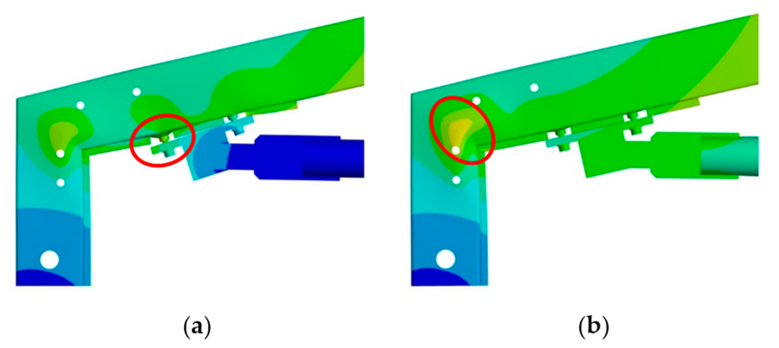
Changing the stiffness of the tie element also led to different failure modes of the knee joint (Figure 17). For the knee joints with a stiffer tie element, numerical analyses showed that the ultimate knee joint failure was caused by failure of the weld between the beam section and the tensile bolt nut. In the case of knee joints with a softer tie element, tensile force in the tie element is much lower, therefore the pull-out of the tensile bolt does not occur. In that case, bending at the beam to column intersection along with web buckling was the dominant cause of joint failure. In real aluminium halls with a tension tie element, the latter failure mode is to be expected, which is favourable since that kind of failure is much more ductile compared to brittle failure where tensile bolt nut pull-out occurs.
Furthermore, joints with a stiffer tie element have discontinuity in force–piston displacement curves after reaching a force value of approx. 40 kN (Figure 15), which is caused by the slip of the manually prestressed bolts that connect the T-adapter to the beam of the steel knee joint. Before reaching force at the piston of 40 kN, force in the tie element is transferred to the knee joint beam by the friction between the T–adapter and the smaller steel tube. After reaching a force at the piston of approx. 40 kN, slip of the bolts occurs in numerical models, causing tension from the tie element to be transferred by the contact between the bolts and the perimeter of holes. This kind of behaviour is much less pronounced in joints with a softer tie element, since slippage of the bolts occurred just prior to reaching ultimate failure.

4. Conclusions

Laboratory tests along with parametric numerical analysis were conducted to examine the steel knee joint flexural behaviour. Three identical steel knee joints with a tie element subjected to a bending moment were tested in a laboratory. Due to the limitations of the laboratory equipment, a steel tube was used as a tie element instead of high-strength steel wire rope, giving a much stiffer joint response that is quite different from the joints in real aluminium portal frame structures. To examine the influence of tie element stiffness on the overall behaviour of the knee joint, the numerical model was calibrated to the laboratory tests and additional numerical parametric analysis was conducted with various tie element stiffnesses. Based on the conducted research, the following conclusions can be drawn:
  • Tested laboratory specimens have similar behaviour, all failing due to weld failure between the beam tube section and the tensile bolt nut.
  • In general, the stiffness of the tie element has very little influence on the bending moment–rotation relationship of the knee joint but has high influence on the force–piston displacement relationship.
  • The influence of the tie element stiffness on the bending moment–rotation and the force–piston displacement relationship is more pronounced in the knee range and especially in the postcritical region.
  • Knee joints with stiffer tie elements are much more prone to tensile bolt (nut) pull-out when reaching failure compared to knee joints with a softer tie element. When a softer tie element is used, web buckling at the beam to column intersection is much more pronounced, giving a more favourable ductile failure mode.
The findings from the research performed lead to the conclusion that steel knee joints with tension tie elements are a good solution for aluminium portal frames. Ductile behaviour and the favourable effect of the soft tie element that is commonly used in practice ensure a safe way of connecting aluminium members without unfavourable welding. To get an overall picture of the complex behaviour of aluminium portal frames, further research should be oriented to the behaviour of aluminium beam-to-column joints with steel inserts.

Author Contributions

This paper was accomplished based on collaborative work of the authors. Conceptualization and development of the main idea of the paper, D.S.; methodology, D.S. and I.Č.; laboratory testing D.S. and I.G.; numerical simulation, I.Č.; validation, all authors; writing—original draft preparation, D.S. and I.Č., manuscript writing related to Section 2.3, I.G., D.S. and I.Č.; literature review and writing—review and editing, all authors; supervision, F.M.M. All authors have read and agreed to the published version of the manuscript

Funding

Laboratory specimens were provided by HALTOR Ltd. Croatia.

Acknowledgments

In this section you can acknowledge any support given which is not covered by the author contribution or funding sections. This may include administrative and technical support, or donations in kind (e.g., materials used for experiments).

Conflicts of Interest

The authors declare that there is no conflict of interest regarding the publication of this paper.

References

  1. Mazzolani, F.M. Structural Applications of Aluminium in Civil Engineering. Struct. Eng. Int. 2006, 16, 280–285. [Google Scholar] [CrossRef]
  2. Skejić, D.; Boko, I.; Torić, N. Aluminium as a material for modern structures. Gradevinar 2015, 67, 1075–1085. [Google Scholar]
  3. Skejić, D.; Mazzolani, F.; Ćurković, I.; Damjanović, D. Experimental Testing of Prefabricated Aluminium Knee Joints Reinforced by Steel. In Proceedings of the INALCO2019: 14th International Aluminium Conference, Tokyo, Japan, 13–15 November 2019; pp. 160–161. [Google Scholar]
  4. Boko, I.; Skejić, D.; Torić, N. Aluminium Structures: Textbook at University of Split and Textbook at University of Zagreb; University of Split, Faculty of Civil Engineering, Architecture and Geodesy: Split, Croatia, 2017. [Google Scholar]
  5. Wilkinson, T.; Hancock, G.J. Tests of Stiffened and Unstiffened Welded Knee Connections in Cold-Formed RHS. In Proceedings of the Tubular Structures VIII: 8th International Symposium on Tubular Structures, Singapore, 26–28 August 1998; pp. 177–186. [Google Scholar]
  6. Wilkinson, T.; Hancock, G.J. Tests of Knee Joints in Cold-Formed Rectangular Hollow Sections; Research Report No.: R779; Department of Civil Engineering, University of Sydney: Sydney, Australia, 1998. [Google Scholar]
  7. Wilkinson, T.; Hancock, G.J. Tests to examine plastic behaviour of knee joints in cold-formed RHS. J. Struct. Eng. 2000, 126, 297–305. [Google Scholar] [CrossRef] [Green Version]
  8. Standards Australia. AS 1163: Structural Steel Hollow Sections; Standards Australia: Sydney, Australia, 1991. [Google Scholar]
  9. Packer, J.A.; Wardenier, J.; Kurobane, Y.; Dutta, D.; Yeomans, N. CIDECT Design Guide No. 3: Design Guide for Rectangular Hollow Section (RHS) Joints under Predominantly Static Loading; Verlag TUV Rheinland GmbH: Koln, Germany, 1992. [Google Scholar]
  10. The, L.H.; Hancock, G. Improving Rotation Capacities of Stiffened Welded Knee Joints between DuraGal C450 RHS; Research Report No.: R832; Department of Civil Engineering, University of Sydney: Sydney, Australia, 2003. [Google Scholar]
  11. Urbonas, K.; Daniūnas, A. Component method extension to steel beam-to-beam and beam-to-column knee joints under bending and axial forces. J. Civ. Eng. Manag. 2005, 11, 217–224. [Google Scholar] [CrossRef]
  12. Daniūnas, A.; Urbonas, K. Characteristics of the semi-rigid bolted steel joints under bending and axial forces and its influence on the frame behaviour. In Proceedings of the 9th International Conference “Modern Building Materials, Structures and Techniques”, Vilnius, Lithuania, 16–18 May 2007; Technika: Vilnius, Lithuania, 2007; pp. 512–516. [Google Scholar]
  13. Mills, J.E. Knee joints in cold-formed channel portal frames: Problems and pitfalls. Aust. J. Struct. Eng. 2012, 13. [Google Scholar] [CrossRef]
  14. Standards Australia. AS/NZS 4600: Cold-Formed Steel Structures; Standards Australia: Sydney, Australia, 2005. [Google Scholar]
  15. European Committee for Standardization (CEN). Eurocode 3: Design of Steel Structures—Part 1–8: Design of Joints (EN 1993-1-8:2005+AC:2009); CEN: Brussels, Belgium, 2014. [Google Scholar]
  16. Packer, J.A.; Wardenier, J.; Zhao, X.-L.; Van der Vegte, G.J.; Kurobane, Y. CIDECT Design Guide No. 3: Design Guide for Rectangular Hollow Section (RHS) Joints under Predominantly Static Loading, 2nd ed.; Verlag TUV Rheinland GmbH: Koln, Germany, 2009. [Google Scholar]
  17. European Committee for Standardization (CEN). Steel Wire Ropes—Safety—Part 1: General Requirements (EN 12385-1:2002+A1:2008); CEN: Brussels, Belgium, 2008. [Google Scholar]
  18. International Organization for Standardization (ISO). Metallic Materials—Tensile Testing—Part 1: Method of Test at Room Temperature (ISO 6892-1:2016; EN ISO 6892-1:2016); ISO: Geneva, Switzerland, 2016. [Google Scholar]
  19. European Committee for Standardization (CEN). Designation Systems for Steels—Part 1: Steel Names (EN 10027-1:2016); CEN: Brussels, Belgium, 2016. [Google Scholar]
  20. International Organization for Standardization (ISO). Welding—Fusion-Welded Joints in Steel, Nickel, Titanium and Their Alloys (Beam Welding Excluded)—Quality Levels for Imperfections (ISO 5817:2014); ISO: Geneva, Switzerland, 2014. [Google Scholar]
  21. Josipović, M. Behaviour of Aluminium Prefabricated Beam-to-Column Joint. Graduate Thesis, Faculty of Civil Engineering, University of Zagreb, Zagreb, Croatia, 2018; p. 135. [Google Scholar]
  22. Harasti, D. Experimental and Numerical Analysis of Aluminium Girder with Steel Infill. Graduate Thesis, Faculty of Civil Engineering, University of Zagreb, Zagreb, Croatia, 2018; p. 71. [Google Scholar]
  23. ANSYS. Workbench User’s Guide (Release 15.0); ANSYS: Canonsburg, PA, USA, 2013. [Google Scholar]
  24. Wyss, T. Stahldrahtseile der Transport und Förderseilen, Schweizer Druck—und Verlagshaus; Schweizer Druck und Verlagshaus: Zürich, Switzerland, 2016. [Google Scholar]
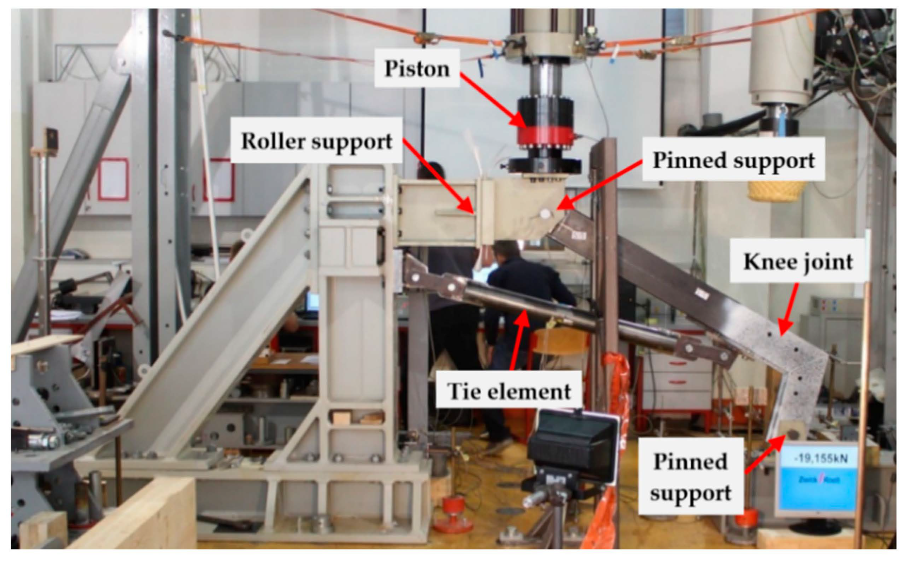
Figure 1. Test setup—a general view.
Applsci 11 00070 g001
Figure 2. Geometrical properties of steel knee joint specimens S1–S3 (dimensions in mm).
Applsci 11 00070 g002
Figure 3. Positions form where coupons were taken and their belonging labels.
Applsci 11 00070 g003
Figure 4. Stress-strain curves with main mechanical properties of tested coupons (RHS 180 × 80 × 3 and RHS 30 × 20 × 2).
Applsci 11 00070 g004
Figure 5. Performed testing procedures of butt welds between the beam and the column: (a) dye penetration test; (b) sample extraction; (c) bending test; (d) macrograph analysis; (e) static tension test.
Applsci 11 00070 g005
Figure 6. Test set-up and measuring devices.
Applsci 11 00070 g006
Figure 7. Force–displacement curves of the steel specimen measured in the piston.
Applsci 11 00070 g007
Figure 8. Loading and boundary conditions of the steel knee specimen (dimensions in mm).
Applsci 11 00070 g008
Figure 9. Moment–rotation curves: (a) rotational behaviour of specimen S1–S3; (b) main properties of the Mj–ϕj curves.
Applsci 11 00070 g009
Figure 10. Failure mode of the steel knee joint: (a) local web buckling in the knee joint connection region; (b) tensile bolt nut weld failure.
Applsci 11 00070 g010
Figure 11. Force in the piston-force in the tie element relationship.
Applsci 11 00070 g011
Figure 12. Numerical model (3D view).
Applsci 11 00070 g012
Figure 13. Comparison between experimental and numerical results: (a) load-displacement; (b) moment–rotation curves.
Applsci 11 00070 g013
Figure 14. Failure mode comparison between: (a) laboratory specimen; (b) numerical model.
Applsci 11 00070 g014
Figure 15. Force–piston displacement curves for different stiffnesses of the tie element.
Applsci 11 00070 g015
Figure 16. Joint bending moment–rotation curves for different stiffnesses of the tie element.
Applsci 11 00070 g016
Figure 17. Comparison of failure modes for different tie element stiffnesses: (a) E’ = 210,000 MPa; (b) E’ = 610 MPa.
Applsci 11 00070 g017
Table 1. Characterization of experimental load–piston displacement curves.
SpecimenFpl [kN]Δpl [mm]Fu [kN]Δu [mm]
S160.011.086.031.2
S264.013.084.030.8
S353.09.5072.723.6
Mean value59.011.280.928.5
Std. Dev.4.551.435.863.49
Table 2. Main properties of the Mj–ϕj curves.
Joint PropertyS1S2S3AvgStd. Dev.
Mj,R [kNm]17.117.616.617.10.408
Mj,el [kNm]12.414.913.713.71.02
Mj,u [kNm]17.918.217.217.80.419
φj,Mu [mrad]19.915.413.916.22.55
φj,u [mrad]39.243.963.348.810.4
Sj,ini [kNm/rad]164116631541161553.1
Table 3. Comparison of the stiffness values of tie elements used in experimental program and the one used in practice.
Portal Frame Span [m].Stiffness Ratio fred [–]E’=E/fred [MPa]
11712,200
2.5434880
5862440
101721220
15258815
20344610
E—modulus of elasticity for steel taken as E = 210 GPa
Publisher’s Note: MDPI stays neutral with regard to jurisdictional claims in published maps and institutional affiliations.