1. Introduction
Endodontic rotary files have experienced continuous development, both in the chemical composition of alloys and geometrical design, which has improved their mechanical behavior during operation [
1]. However, unexpected fractures of endodontic rotary files within the root canal system are still a concern and remain a challenge for clinicians despite continuous enhancements in their geometrical design and manufacture processes to reduce the incidence of fractures [
2], which ranges from
to
[
3,
4].
Previous studies have suggested that flexural failure (bending) and torsional failure are the main causes for endodontic rotary file fractures [
5,
6,
7]. Torsional failure is caused by the blockage of the endodontic files during rotational movement [
5]; however, endodontic rotary instrument failures are mainly caused by cyclic bending fatigue, which occurs when a endodontic rotary instrument rotates in a curved root canal [
8]. In addition, endodontic rotary files can be simultaneously subjected to cumulative torsional and bending stress during root canal shaping, which can lead to the fracture of endodontic rotary files and therefore affect the prognosis of root canal treatment as the fractured fragment blocks the access to the apex, preventing root canal system disinfection [
9,
10].
In addition, root canal dentine removal during the retrieval procedures of separated files can weaken the tooth structure up to 4.25 ± 0.68 mm
[
11]. Moreover, fractures of endodontic instruments on teeth with periapical pathology significantly decrease the success rate of root canal treatment [
12]. Therefore, improvements of the chemical composition of the alloy and geometrical design may increase torsional and bending resistance, preventing the fracture of the endodontic rotary instruments [
13]. Furthermore, some geometrical factors have been highlighted as influencing the instrument’s performance, such as taper [
14], apical diameter [
7,
14], cross section [
15], flute length, helix angle and pitch [
16]; however, most studies were conducted experimentally using custom-made cyclic fatigue devices, hardly reproducing the clinical setting and the absence of regulation prevents data comparison [
17].
However, finite element (FE) analysis is an alternative that allows the mechanical behavior and stress distribution of endodontic rotary instruments subjected to different conditions to be simulated through mathematical analysis [
18]. Moreover, FE analyses have been previously used in endodontics to assess both the mechanical behavior of endodontic instruments [
19] and stress distribution during root canal treatments [
16].
Two different approaches can be found in recent works when developing FE models for the stress analysis of endodontic files, which differ in the way in which the endodontic file geometry is obtained. In both cases, the obtained geometry must be converted to a finite element model by means of a FE analysis pre-processor, in order to proceed to its analysis. In addition, elevated solid mechanics knowledge is required in both cases, in order to define a finite element model that can accurately reproduce the physics of the problem.
In the most conventional approach [
1,
20,
21], the generation of the geometry of the file is conducted through computer-aided design (CAD) software. This approach requires elevated CAD knowledge to accurately reproduce the geometric characterization of the endodontic rotary file parameters. In fact, there are several cases in which the generated geometries cannot accurately reproduce the geometry of the actual endodontic file, especially at the transition between the active part and the shaft.
In another approach [
22], the geometry of the endodontic file is obtained from a tomography scanner. This approach requires expensive equipment in order to obtain the computer representation from the tomography scanner and elevated knowledge to manipulate the obtained geometry files.
Both processes are costly in terms of time and have to be accomplished for each assigned case of design of various geometries and cases of investigation. Therefore, generating an automated procedure that simplifies the procedures described above and enables the performance of FE analyses without the need for this knowledge will help us to better understand the mechanical behavior of endodontic rotary files under various conditions. Thus, the aims of this work are as follows:
To develop an automated procedure to obtain an accurate description of the geometry of the endodontic file from its design parameters;
To develop an automated procedure to obtain an FE model of the endodontic file from the generated geometry;
To demonstrate the capabilities of the proposed procedures.
2. Materials and Methods
This section describes a new method developed for the computerized generation of endodontic files and the obtention of FE models for their stress analysis. The geometry considered for the endodontic file is shown in
Figure 1a. It is defined with respect to a coordinate system
, whose
axis is alined with the theoretical axis of rotation of the endodontic file and its origin
is at the tip of the endodontic file. The geometry of the endodontic file is fully parametrized by the following set of parameters:
The diameter of the shaft, ;
The diameter of the tip of the active part, ;
The length of the active part, ;
The total length of the file, ;
The pitch of the active part, , which represents the distance between adjacent points in the cutting edge.
Three different parts can be identified for this endodontic file: the active part, the shaft and the transition part. The active part contains the cutting edges and has an arbitrary cross section (squared, triangular, etc.). The shaft has a circular cross section and connects the active part with the support of the endodontic file (which is not included in this model). Finally, the transition part allows for a smooth transition from the cross section of the active part to the cross section of the shaft.
Figure 2 shows an example of the cross section of the endodontic file at each one of these parts.
The computerized generation of this endodontic file is achieved as the intersection of two different geometries: the raw material (
Figure 1b) and the machined material (
Figure 1c). The raw material corresponds to a geometry of the endodontic file before the cutting edges are machined over it, and its generation is described in
Section 2.1. The geometry of the machined material is an auxiliary geometry that is used to generate the cutting edges of the endodontic file, and its generation is described in
Section 2.2. The intersection of both geometries and the obtention of the final geometry of the endodontic file is described in
Section 2.3.
Having a computational description of the geometry of the endodontic file allows for an automated generation of FE models for its stress analysis.
Section 2.4 provides further details on how to obtain these FE models.
2.1. Definition of the Geometry of the Raw Material for the Endodontic File
The raw material (
Figure 1b) has an axisymmetric geometry that consists of two different parts:
A cylindrical part, which corresponds to the shaft, characterized by its length () and its diameter ();
A truncated cone, which corresponds to the active part. It is characterized by its length () and its diameters at the front () and back ends ().
The position of a point
P on the surface of the raw material is given by the parametric equation
, which provides the coordinates of point
P in coordinate system
from its parametric coordinates
and
:
where angle
is defined as a function of
v; assuming a constant pitch
along the endondontic file, it can be defined as
On the other hand,
represents the diameter of the raw material at coordinate
v, and it is defined as
2.2. Definition of the Geometry of the Machined Material for the Endodontic File
The machined material (
Figure 1c) is an auxiliary geometry that is used for the generation of the geometry of the endodontic file, and it is obtained from the transformation (rotation, translation and scalation) of an arbitrary cross section.
For the definition of this geometry, let us consider an auxiliary coordinate system
, whose
axis is parallel to the
axis of coordinate system
, as indicated in
Figure 3 left. The origin of coordinate system
is located on axis
at a distance
v from
, and
is rotated with respect to
an angle
.
The cross section of the machined material is defined with respect to coordinate system
, and it is circumscribed into a normalized circumference (d = 1 mm), as illustrated in
Figure 3 right for the particular case of a squared cross section. The position of any point
P over the contour of the file section is defined by a parametric function
that provides, for a given parametric coordinate
, the homogeneous coordinates [
23] of point
P in coordinate system
:
where
, since the cross section is contained in the
plane. In the particular case of squared transversal cross section,
and
can be defined as
where d = 1 mm is the diameter of the normalized circumference. The definitions of
and
for other transversal cross sections can be trivially derived.
The position of a point
P on the surface of the machined material is given by the parametric equation
, which provides the homogeneous coordinates of point
P in coordinate system
from its parametric coordinates
and
:
where
is given by Equation (
4),
v is a distance coordinate (see
Figure 3) and
is a transformation matrix defined as
The advantage of using homogeneous coordinates is that the transformation matrix allows three simultaneous transformations of the transversal cross section of the machined material to be performed:
The translation of the cross section a distance v along the axis;
The rotation of the cross section at an angle around the axis;
The scaling of the cross section in the plane by a factor .
The angle
is defined as a function of
v and, assuming a constant pitch
along the endondontic file, this angle can be defined as
Note that the equality
must be satisfied to guarantee the robustness of the proposed formulation. On the other hand, the scale factor
is defined as
In the interval corresponding to the active part, it is fulfilled that . In the transition part and the shaft, , because a quadratic term is included in the definition of . This quadratic term allows for a smooth transition from the machined material to the raw material, and it is characterized by the parabola coefficient .
2.3. Definition of the Geometry of the Endodontic File
The final geometry of the endodontic file is obtained from the intersection of the geometries of the raw material and machined material, as described above. In order to compute this intersection, it is necessary to compute the inner point of these geometries for the same
and
v coordinates. For such a purpose, the distance from any point in the cross section to the
axis needs to be calculated. Distances
and
are defined for the raw material and the machined material (respectively) as
where
is the unit vector in the direction given by the
axis of the coordinate system
.
Note that
does not depend on
because the raw material has a circular cross section and, in consequence, all the points within the section are at the same distance of
. According to the definition of the scaling factors for the geometries of the raw material and the machine material, the following statements are fulfilled (see
Figure 2):
In the active part of the endodontic file, ;
In the shaft of the endodontic file, ;
In the transition part of the endodontic file, the relation between and cannot be known in advance.
Taking this into account, the geometry of the endodontic file is represented in coordinate system
by function
as
2.4. Development of an Fe Model for Stress Analysis of Endodontic Files
This section describes a new procedure for the automated development of FE models for the stress analysis of endodontic files. This procedure covers the typical steps in the generation of an FE model for stress analysis, which include the discretization of the volume of the endodontic file into finite elements, the definition of the material properties for the finite elements of the model and the definition of the loading and boundary conditions of the model.
In the first step, the volume of the endodontic file is discretized into tetrahedral elements by means of a constrained Delaunay tetrahedralization [
24]. The constrained Delaunay tetrahedralization requires the boundary surfaces of the endodontic file to be represented by a set of triangles, which will constitute the external faces of the tetrahedrons once the mesh is generated. This boundary representation is achieved following these steps:
Using this boundary representation of the endodontic file, the tetrahedral mesh is constructed using the constrained Delaunay tetrahedralization implemented in the TetGen library [
25]. This tetrahedralization does not change the position of the nodes defined for the endodontic file surface, and the resulting tetrahedrons keep the faces provided as input information.
When the FE mesh is generated, mechanical properties are assigned to its elements. The mechanical response of a material in its elastic range can be defined by the elastic modulus
E and the Poisson’s coefficient
. Assuming the endondontic file is manufactured using a NiTi alloy, these material parameters are established as
and
[
1]. Of course, the user can specify other values.
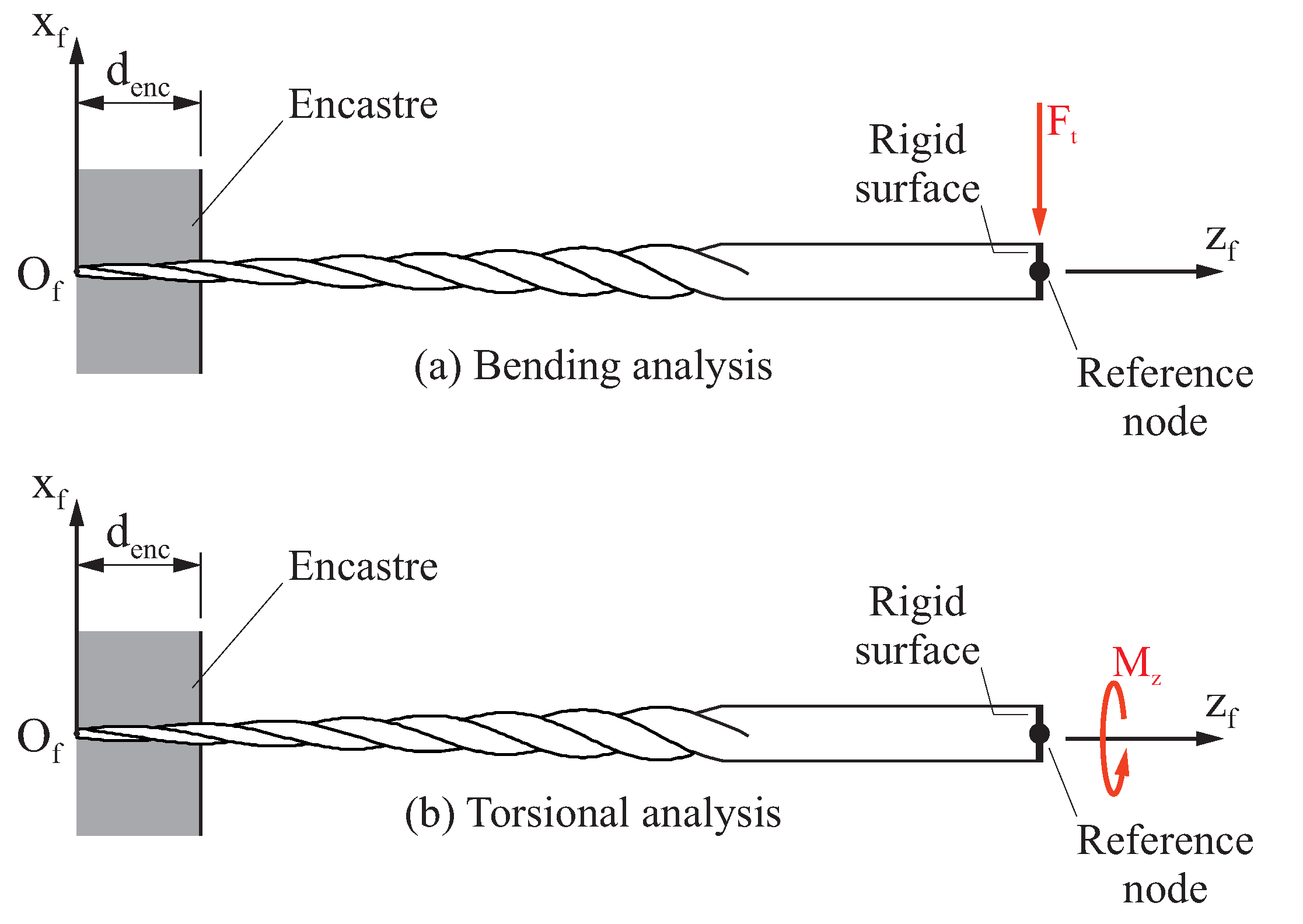
In the last step, the loading and boundary conditions for the FE model are established. Endodontic files are usually tested for bending and torsional loads, and the typical procedure for these tests is described in [
26] and summarized in
Figure 4. In these analyses, the endodontic file is approached to a cantilever beam. A fixed support is defined at a distance
from the tip of the endodontic file, in such a way that all the nodes below that dimension have all their degrees of freedom constrained. Typical magnitudes for
are between
[
2,
20,
22,
27,
28] and
[
29], although other values could be considered [
1,
21].
Loads are specified at the other part of the endodontic file. For such a purpose, a rigid surface is defined comprising all the nodes within the end face. A reference node is defined at the center of this face, whose movements are coupled to the movements of the rigid surface by means of a multi-point constraint. Loads are applied directly over this reference node. Two different load cases are derived to study the bending (
Figure 4a) and torsional (
Figure 4b) response of the endodontic file. In the first of them (
Figure 4a), a tangential load
is introduced over the reference node; in the second (
Figure 4b), a torsional moment
is considered over this reference node.
This procedure provides an input file for the FE solver that contains the entire definition of the FE model. It must be emphasized that this implementation allows for the development of fully parametrized FE models, in which the geometry, the mesh density, the material parameters and the loading conditions can be specified by the user without using any other third-party software.
3. Results
The developed procedure has been implemented in Matlab R2018 [
30] (MathWorks Inc., Natick, MA, USA). A graphical interface, which is shown in
Figure 5, has been programmed to ease the specification of the endodontic file geometry and the configuration of the FE model. After completing all the parameters that define the model, this software provides an input file for the FE solver, which contains the entire definition of the FE model.
The performance of the proposed procedure and its computational implementation is illustrated with the generation and stress analysis of an endodontic file, which is defined by the set of parameters shown in
Table 1.
Two different load cases are considered in this study, according to Bonessio et al. [
27] and De Arruda Santos et al. [
28]. In the first load case, the bending behavior of the endodontic file is studied by considering a transversal force
. In the second load case, the torsional behavior of the endodontic file is studied by considering a torsional moment
. In both cases, the length of the encastre is
.
3.1. Mesh Convergence Study
A mesh convergence study has been conducted to establish the optimum size and type for the elements of the mesh. In this study, several finite element models are obtained for the endodontic file, in which the density of the mesh is progressively increased by varying the magnitudes of
and
. Four different average element sizes have been considered in the analysis, which vary from
to
, and both linear and quadratic tetrahedral elements have been taken into account.
Figure 6 shows one of the meshes used in this study, in which the endodontic file is meshed using quadratic tetrahedrons with an average element size of
(
and
). The resulting FE models were analyzed using ABAQUS [
31] (Dassault Systèmes Simulia Corp, Providence, RI, USA).
As suggested by Żmudzki [
32,
33], the convergence of the mesh can be assessed by means of an error energy norm
E. In this error estimator, the stress vector
and the averaged stress vector
are used to determine a stress error vector
:
Then, for a given element
i of the mesh and following the ideas presented by Zienkiewicz [
34], an element energy error
is determined as:
where
is the material elasticity matrix and
denotes the volume of element
i. The energy error
e is estimated for the whole finite element model as the sum of the error contributions of all the elements in the mesh:
where
denotes the number of elements in the mesh. Finally, and considering the total strain energy of the finite element model
U, the error energy norm
E is calculated as:
Figure 7a shows the evolution of the error energy norm
E as a function of the average element size, determined for each load case (torsion and bending) and element type (linear and quadratic). In all the cases, it can be observed that reducing the average element size also decreases the error in energy norm. For any load case and average element size, the error energy norm is significantly smaller when the problem is solved using quadratic elements than when it is solved using linear elements.
Figure 7b shows the maximum element energy error
determined for each load case (torsion and bending) and element type (linear and quadratic), as a function of the average element size. The trends observed in this figure are similar to the ones observed in
Figure 7a. In general, the maximum element energy error is reduced as the average element size is decreased, and quadratic elements demonstrate a better performance than linear elements. In all the cases the element with the maximum element energy error is found in the vicinity of the encastre, indicating that this is the region of the finite element model where mesh refinement is more needed.
Although there is no universal agreement over which is the error in energy norm that can be used as a threshold to validate the convergence of a given finite element mesh, an error in energy norm of
has been used in some works [
35] for such a purpose. Taking this into consideration, and examining the results shown in
Figure 7a, it could be said that in this case the mesh convergence is achieved when the finite element model is built using quadratic elements and the average element size is equal or less than
.
3.2. Interpretation of the Results of the Stress Analysis
Figure 8 shows a von Mises stress plot along the endodontic file, which is obtained from a torsional analysis in which the finite element model is built with quadratic elements with an average element size of
. The maximum von Mises stress reached in this analysis is
, and it is produced in the vicinity of the encastre (but not in the encastre itself, as it can be observed in the detail of
Figure 8). The figure also shows the stress distribution along the cross section where maximum von Mises stress takes place. In both cases, the stress results follow the expected distribution for this type of analyses. The rotation at the free end of the file
.
Figure 9 shows a von Mises stress plot along the endodontic file, which is obtained from a bending analysis in which the finite element model is built with quadratic elements with an average element size of
. The maximum von Mises stress reached in this analysis is
, and it is produced in the vicinity of the encastre. The figure also shows the stress distribution along the cross section where the maximum stress is found. In both cases, the stress results follow the expected distribution for this type of analyses. The deflection at the free end of the file is
.
Unlike in the torsional analysis, in the bending analysis the maximum von Mises stress occurs in a node where a boundary condition is applied and, as a consequence, a numerical singularity is produced that leads to unrealistic stress values. This issue is illustrated in
Figure 10a, where a detail of the von Mises stress plot over the area where the bending stresses reach their maximum value is shown. This figure also displays the von Misses stress values at the nodes of the edge where the maximum stress takes place. It can be observed that the maximum value of
, produced at the node in the corner of the encastre section, is unreasonably high considering the stress magnitude at the surrounding nodes.
According to many researchers [
36,
37], these stress results at singularity points cannot be considered to evaluate the strength of the endodontic file. To get around this issue, Żmudzki [
32] proposes to exclude the stress results at these points and then extrapolate the extreme value from the stress values in the remaining nodes. Following this idea,
Figure 10b shows a plot of the evolution of the von Mises stress along the observed edge. A polynomial approximation to the stress values has been obtained, discarding the maximum value of
. Following this approximation, the predicted von Misses stress value at the encastre is
, leaving the maximum von Mises stress of the model at
.
3.3. Parametric Study
The developed procedure allows for a simple and fast generation of finite element models of endodontic files, and, in consequence, it is especially suitable for performing parametric and optimization studies. In this section, the performance of the proposed procedure is illustrated with three parametric studies, in which the pitch of the active part, the length of the active part and the diameter of the tip were varied. In each parametric study, only one parameter was varied and the rest were kept constant and equal to those shown in
Table 1.
Figure 11 shows the results obtained from the parametric study in which the pitch of the active part was varied. Four different magnitudes were considered for the pitch of the active part, which were between
and
. In each case, the endodontic file has been conveniently rotated so the orientation of the cross section at the encastre coincides with that shown in
Figure 9.
Figure 11a shows the results for the bending analysis. It can be observed that both the maximum von Mises stress and tip deflection reduced as the pitch of the active part increased. The maximum von Mises stress decreased from
(when
) to
(when
). The tip deflection decreased from
(when
) to
(when
).
On the other hand,
Figure 11b shows the results for the torsional analysis. In this case, minor variations are observed for the maximum von Mises stress and the tip rotation, indicating that these parameters may be independent of the pitch of the active part (at least in the observed range).
Figure 12 shows the results obtained from the parametric study in which the length of the active part was varied. Five different magnitudes were considered for the length of the active part, which were between
and
.
Figure 12a shows the results for the bending analysis. It can be observed that both the maximum von Mises stress and tip deflection increased as the length of the active part increased. The maximum von Mises stress increased from
(when
) to
(when
). The tip deflection increased from
(when
) to
(when
).
On the other hand,
Figure 12b shows the results for the torsional analysis. As happened in the bending analysis, both the maximum von Mises stress and tip rotation increased as the length of the active part increased. The maximum von Mises stress increased from
(when
) to
(when
). The tip rotation increased from
(when
) to
(when
).
Finally,
Figure 13 shows the results obtained from the parametric study in which the diameter of the tip of the active part was varied. Four different magnitudes were considered for the diameter of the tip of the active part, which were between
and
.
Figure 13a shows the results for the bending analysis. It can be observed that both the maximum von Mises stress and tip deflection decreased as the diameter of the tip of the active part increased. The maximum von Mises stress decreased from
(when
) to
(when
). The tip deflection decreased from
(when
) to
(when
).
On the other hand,
Figure 13b shows the results for the torsional analysis. As happened in the bending analysis, both the maximum von Mises stress and tip rotation decreased as the diameter of the tip of the active part increased. The maximum von Mises stress decreased from
(when
) to
(when
). The tip rotation decreased from
(when
) to
(when
).
4. Discussion
FE models have been proposed to analyze the mechanical performance of endodontic rotary files, isolating the variables independently under controlled settings [
38] to facilitate the comparison between the mechanical behavior and stress distribution of existing endodontic rotary files and even to allow the design of new endodontic rotary instruments by reducing time and costs [
27]. In addition, He and Ni used FE methods to improve the geometrical design of existing endodontic rotary instruments and therefore the mechanical behavior under bending and torsional loads to reduce the prevalence of failure [
2].
He and Ni also analyzed the influence of the helix angle, taper and flute length on the bending flexibility and torsional stiffness of endodontic files (V-Taper) through numerical simulations and concluded that the geometric features influence on the mechanical performance of endodontic files under bending and torsional conditions [
2]. Arbab-Chirani et al. compared numerically the mechanical behavior of Hero, HeroShaper, ProFile, Wtwo and ProTaper F1 endodontic rotary NiTi instruments under bending and torsional conditions and showed that the different designs for tapers, pitch and cutting blades influence on the bending and torsional mechanical behavior [
39]. Baek et al. evaluated the effect from pitch and cross-section design on torsional stiffness of NiTi endodontic rotary instruments and evidenced that torsional deformation and fracture of NiTi rotary files might be reduced by reducing the pitch and increasing the cross-sectional areas rather than the center core area [
40].
Although metallurgical properties and metallurgical treatments have been shown to influence the properties of NiTi endodontic rotary instruments, geometrical design has been highlighted to be directly related to the stiffness [
41], clinical efficiency and cutting performance of endodontic rotary files [
29,
42]. The cross-section design of endodontic rotary files has experienced a continuous development; Versluis et al. reported that increasing the cross-sectional surface area lead to a decrease in the flexibility of endodontic rotary files by a stress accumulation at the upper and lower edges of the cross section during bending tests, compared with smaller cross-sectional surface areas [
17].
In addition, cross-sectional morphology has been also widely analyzed, and Galal and Hamdy reported that a convex triangular cross-section design showed maximum von Misses stresses upon bending tests (), followed by a triangular cross-section design (), parallelogram cross-section design () and rectangular cross-section design (); however, a convex triangular cross-section design showed maximum von Misses stresses upon torsional tests (), followed by a triangular cross-section design (), rectangular cross-section design () and parallelogram cross-section design ().
Additionally, the stress distribution pattern was localized at the cutting edges under bending tests and more concentrated in the base of the flutes in the first
of the triangular cross-section design under torsional tests [
43]. These results agree with the findings reported by Tsao et al., who showed a maximum von Misses stress of
at the cutting edges of a triangular cross-section design endodontic rotary file after applying a transverse load of
at the tip of the endodontic rotary file during bending tests [
44]; additionally, Prados-Privado et al. showed a maximum von Misses stress of
at the convex triangular cross-section design of a Wave One endodontic reciprocating file, followed by the S-shaped cross-section design of Reciproc
), the parallelogram cross-section design of WaveOne Gold (
) and the S-shaped cross-section design of Reciproc Blue (
) under bending conditions.
However, torsional resistance tests showed a maximum von Misses stress of
at the WaveOne endodontic reciprocating files, followed by Reciproc (
), Reciproc Blue (
) and WaveOneGold (
) [
20]; however, these results are not aligned with those obtained in the present study, possibly because the authors used a different cross-section design (squared) and also a lower transverse load
.
However, FE methods require elevated CAD knowledge to accurately reproduce the geometric characterization of the endodontic rotary file parameters as well as numerical analysis knowledge to simulate the mechanical behavior and stress distribution during bending and torsional resistance tests. In addition, some drawbacks related to FE models have been highlighted as they used to be difficult and expensive to build, complex and time-consuming; furthermore, the formulations can be complicated and they have difficulty in dealing with complex geometry problems [
29]. Therefore, the analytical model proposed in this study represents a solution to generate FE models repeatably.
5. Conclusions
In this work, a new procedure for the computerized generation of the geometry of endodontic rotary files and the automated creation of finite element models for the stress analysis of endodontic files is proposed. This new procedure allows us to create fully parametrized finite element models of the endodontic files directly from their design and material parameters.
The proposed procedure has been used to implement computer software, and its performance has been demonstrated by means of numerical examples. In general, it can be said that the proposed procedure can help to increase the accuracy with which the geometry of the finite element models of the rotary files can be generated and, at the same time, simplifies the analysis process and reduces time consumption.


 ,
, 


