2.1. Land Surveyor Profession in Romania
Surveying engineers are people who work both in the field taking measurements, as well as in the office, analyzing the measured data and planning maps, technical plans and registering legal documents regarding boundaries of existing land parcels. It is often said that surveyor engineers are the first persons to enter the construction site, and the last to leave it. This is because the inception of any investment construction project starts from the legal documents regarding the location, as well as feasibility studies that involve topographic surveys in order to provide geo-spatial data to the architects, civil engineers and other design engineers.
In Romania, the profession of survey engineering is called topographer or geodetic engineer. Compared to other countries, in Romania this profession combines the knowledge, attributions and responsibility of both land surveyors and building surveyors. In essence, a Romanian topographer or geodetic engineer is the person who consults and works with the legal aspects of property law, such as boundary surveys and cadastre, as well as the technical aspects that involve the construction industry, such as guiding the construction of new structures such as infrastructures or buildings.
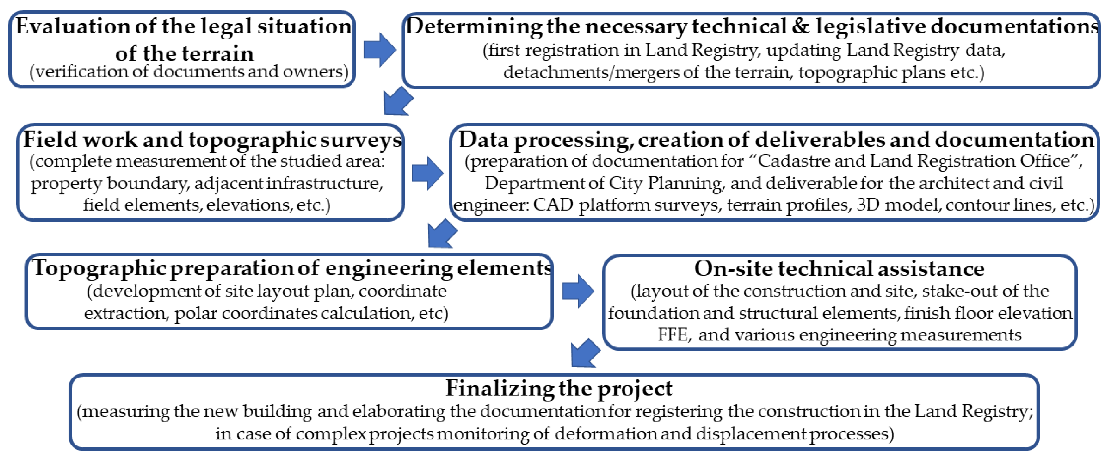
In order to practice this profession, a bachelor’s degree is required, as well as a number of years of experience in order to become an authorized or licensed surveyor, with one of the four different levels of qualification: C, B, A and D (highest). These levels of qualification require different years of experience, portfolio of survey works and different types of examination and interviews. As a license to practice, a category C surveyor can only work in cadastre and land surveys, categories B and A, beside the previous category C competencies, can design technical topographical plans, building surveys, layout or stake-out of reference points and markers for constructions and, lastly category D, which incorporates the previous competencies, can also create or verify geodetic networks. The authority that grants these licenses to practice is the National Agency for Cadastre and Land Registration, a government institution that oversees the property law and cadastre in the country. A typical workflow for a survey engineer is as follows (
Figure 1):
The preliminary work consists of consultancy and evaluation of the legal situation of the terrain, as for any building permit it is necessary to have a clear property law, checking property boundaries and assigning a cadastral number. In order to prepare the terrain for investment, besides the land registry data integrity, the shape of the terrain has to be considered, thus there is often documentation for land parcel detachments or mergers. The topographic plan is necessary for both the technical documentation for obtaining the building permit, as well as for the design of the architect and civil engineer, by providing a series of complex works and deliverables such as: computer-aided design (CAD) platform surveys, transverse and longitudinal terrain profiles, 3D modeling of the terrain, contour lines and other elements that are the basis for the architecture, structure and design projects. Works during the construction process include regular site topographic assistance, where the surveyor engineer ensures the connection between the design made by the architect/civil engineer and the builder/contractor. In order to ensure the accuracy of the site position of the designed structural elements, it is necessary to layout or stake-out building reference points as well as construction axes and geometry, markers of finish floor elevations, verifications of various elements and elevations, verticality studies, quantity calculation, monitoring of adjacent buildings and other engineering measurements. Works after completion of constructions include: “As-Built” plan necessary to detect non-conformities between what was built and the project; topographic plans and cadastral works in order to connect the new constructions to utilities and registration in property law; in the case of apartment buildings additional detachment documentations and surveys of interior spaces; and, finally, in the case of complex projects, monitoring of the new building in order to determine its behavior during the period of construction.
2.2. Site Location and Conditions
In the constant expanding and highly populated Cluj-Napoca metropolitan area, Romania (
Figure 2), the need for qualitative, safe, time and cost-efficient survey engineering works is imperative. With a general move towards urbanization, the construction industry is booming, land is becoming an increasingly difficult resource to obtain and the construction market is a desideratum [
20,
21]. The unprecedented urban sprawl phenomenon imposed the expansion of the city limits and the transformation of adjacent villages, agricultural terrains or old industrial parks from Cluj-Napoca into suburbs and residential complexes [
22]. Given the current situation, the surveying engineer is a sought-after specialist who can provide multifunctional services for investors such as legal and technical consultancy regarding property law, initial field measurements for the construction design, and on-site technical assistance, up to the final stages of the investment project. Although most of the big construction companies have their own survey engineers, small and medium firms do not and they rely on contracts of service providers with survey engineering companies or licensed individuals. These issues call for a retrospective look at the main technical assistance that survey engineers provide on the construction site (to stake out reference points and markers that will guide the construction of new structures), as well as guidelines for efficient site layout plan creation and the use of on-site batter boards marked with layout lines for future positioning of construction reference points by the builder/contractor.
The present technical project consists of the construction of 2 duplex houses having four living units, in a newly developed neighborhood consisting mainly of houses on the outskirts of Cluj-Napoca (
Figure 2). The terrain has an area of 1147 square meters, the designed duplex houses have a low height regime specific to the region, with ground floor and first floor, and each duplex has a double partition wall between the units, thus having the possibility to be registered in property law as four distinct houses. Each designed unit has a usable area of approximately 120 square meters, 2 parking spaces and a garden of approximately 215 square meters, thus making it a perfect solution for young families.
2.3. Methodological Approach and Instrumentation
The methodological structure pursued to develop the presented study is in accordance with the general line of technical notes and practices in the field. Thus, in the present study, the research direction was divided in two main stages of dissemination: that of evaluating the methodological process of obtaining an efficient site layout plan, with a retrospective look at the design and field-work practiced notions; the second main stage, represents the on-site applied designs, together with a novelty comparison between four methods of batter boards stake-out of the construction layout lines, in order to determine the most qualitative, safe, time and cost-efficient one, as well as highlighting advantages and disadvantages of each method and the possible instrumentation used.
To better understand the workflow of such a project, a graphical abstract of the site layout plan process was created (
Figure 3). As previously mentioned, the surveyor engineer’s work starts in the office with evaluating the land registry of the terrain, in order to determine the required technical and legislative documentation. Once this stage is complete, an elaborate field measurement is scheduled, with the necessary presence of the land owners or investors. In this topographic survey, the geodetic engineer can either divide his workflow in measurements for cadastral purposes, technical purposes, or combine both of them. Measurements for cadastral purposes are more straightforward, with an emphasis on the boundaries of the property, checking for inadvertences between the measured area and the one in the documents, and accessibility to the terrain. The measurement for technical purposes is much more complex, and requires the data acquisition necessary to create topographic plans for the building permit, as well as deliverables to the architect, civil engineer and other design engineers. It is the survey engineer’s duty to accurately and in great detail represent the terrain surface, in order to develop an investment project. The required deliverables differ depending on the type of project, but the most common ones are the following: a CAD platform complete survey of the study area, with the cadastre contours layer; a 3D model of the terrain and contour lines, achieved also in CAD software; transversal or longitudinal profiles, which are necessary especially for infrastructure. Based on these deliverables, together with a clear property law of the terrain and the topographic plan signed and sealed from the Office of Cadastre and Land Registration, the architect and civil engineer can apply for the Building Permit at the local Department of City Planning. This operation can take up to 6 months, depending on the complexity of the project and the urbanistic regulation in the proposed area. Once the Building Permit is obtained, and the owners or investors have also contracted a team of builders, the need for the survey engineer is again required. The survey engineer must obtain from the design team the site/location plan, which details the geometry and location of the designed building inside the terrain, as well as dimensions between the layout lines or building axes, and distances from the boundary limits to the construction. Even though the initial survey may have been undertaken within a geodetic datum and dimensions, the design team, especially the architects, work in millimeter units and different design softwares, thus the site/location plan received must be converted into the correct coordinate system (in the current case, Stereographic 1970). This process is undertaken in the preferred software of the survey engineer (customarily AutoCAD), and involves the correct cadastral contour and the functions of scale, move and rotate. The desideratum is the creation of the Site Layout Plan, a comprehensive design that highlights the layout of the proposed construction inside the terrain, together with the coordinates and the stake-out elements of the building reference points (usually axes intersections). The stake-out elements consist of horizontal angles and distances from known geodetic points or control points, together with the instrumentation and layout method used in order to mark the position of the designed building. These horizontal angles and distances can be calculated from the Cartesian coordinates of the control/geodetical points and the designed points of the building, and can be done manually or by spreadsheet software. Total stations have the processing capabilities of instantly calculating these values, but it is recommended to also have them calculated and displayed on the final site layout plan.
In terms of used instrumentation, the total station and GNSS systems are the most used by the survey engineer. GNSS systems are the perfect choice for topographical surveys where the field conditions are optimal (sufficient satellite availability, network RTK services, open field etc.). In recent decades, GNSS systems have been used to obtain geodetic networks or control points, for precise measurements, accurate monitoring processes or construction stake-outs. In the case of classical methods of determining new geodetic points, by means of resection or traverse networks, a current deficiency is the lack of reliable control points or geodetic points, almost completely destroyed in the past decades. The total station is often considered the right hand of the survey engineer, and offers pinpoint accuracy and can yield precise observations, as well as efficient and reliable layout of reference points. The instruments used in this case study were: Leica Viva GS08 Global Navigation Satellite System used in real-time kinematics (RTK) mode for obtaining the control points (St1 and St2) with a horizontal precision between 0.014 m and 0.020 m ensured by online RTK corrections provided by the Romanian Position Determination System (ROMPOS) and the connection to a national permanent GNSS reference station; the total station used was a Leica TS02plus, which has a very good measurement accuracy of angles of 3″ and distances of ±2 mm + 2 ppm.
2.4. Layout of a Project Point and Accuracy Evaluation
Construction layout or stake-out is one of the most important missions of the surveying engineer, with the purpose of ensuring the designed geometries of the engineering structure, by satisfying the required accuracies from the project [
2,
22,
23,
24,
25]. Although modern GNSS systems have the capability of point stake-out with an accuracy of ≈2 cm in the right conditions, construction surveys and layouts are made using total stations. The principle behind a total station stake-out is the polar coordinates method, which consist of calculating and determining the position of a horizontal angle and a distance from a set of two control points (or geodetic points). The two control points are used for instrument stationing and orientation (or bearing), and all calculations regarding the layout of the construction are made in accordance to the established layout network. It was opted for the GNSS technology for the creation of the layout network, because of the efficiency, the lower cost price, and the short time to perform the measurements. In the case of classical methods of determining new geodetic points, by means of resection or traverse networks, the current great deficiency is the lack of reliable control points or geodetic points, almost completely destroyed in the past decades [
13].
The layout elements (horizontal angle and a distance) are calculated using the known coordinates of the layout network and the designed coordinates of the construction, as follows (example for layout point H7;
Figure 4):
In order to ensure an accurate and efficient layout of the construction points, a retrospective of the measurement errors, required accuracy and the construction tolerances must be taken into account [
2,
21,
22]. The type of building and the building technology are also important aspects, as the components and structural elements used to construct buildings are often fabricated, assembled or built on site, often by hand, in conditions that may be less than ideal. Errorless measurements are impossible, thus it is mandatory to satisfy the recommended accuracies through the “achieved point standard deviation” which is defined by the product of the errors derived from known point coordinates and the layout measurements. In order to assure the required accuracy, the achieved accuracy must be smaller than the required one. Based on the type of construction and the characteristics of the engineering structure, the required point standard deviation (±μ
P) should be: μ
P = ±(1–2) cm for the majority of layout construction projects that use a monobloc structure with build on site structural elements (reinforced concrete); μ
P = ±(2–5) mm for prefabricated and assembled structural elements; μ
P = ±(1–2) mm for precise machine guidance and complex structures [
2,
26,
27]. It is the surveying engineer’s mission to identify the required accuracy and plan the layout process in accordance. The achieved accuracy if the resultant of error affecting the measurements of the layout elements, expressed as achieved point standard deviation (±σ
P), and must satisfy the required accuracy:
The errors concerning the measurements are classified into three major groups: instrumental errors, personal errors and atmospheric errors [
28,
29,
30]. Given the present case study, the length of the observations are short and the measurements are made in optimal conditions, as well as through the expertise of the surveying engineers. Thus, personal and atmospheric errors can be considered insignificant and not taken into consideration. The major instrumental errors can be eliminated or significantly reduced by additional checks and calibrations. Given the fact that the measurements are carried out with a new model of the total station with good specifications, it is possible to satisfy the required accuracies of the layout project by using angle and distance reading with only one face of the instrument. By combining the expertise of the survey engineers, the correct checks and calibrations of the instrument, and by using angle readings that not exceed ±(5–10)
cc with layout distances of ±(2–3) mm, the achieved point standard deviation can easily be between σ
P = ±(5–10) mm, more than enough considering the required point standard deviation (±μ
P) for the type of construction and building technology of the present case study.
2.5. Designing the Site Layout Plan and Calculating the Stake-Out Elements
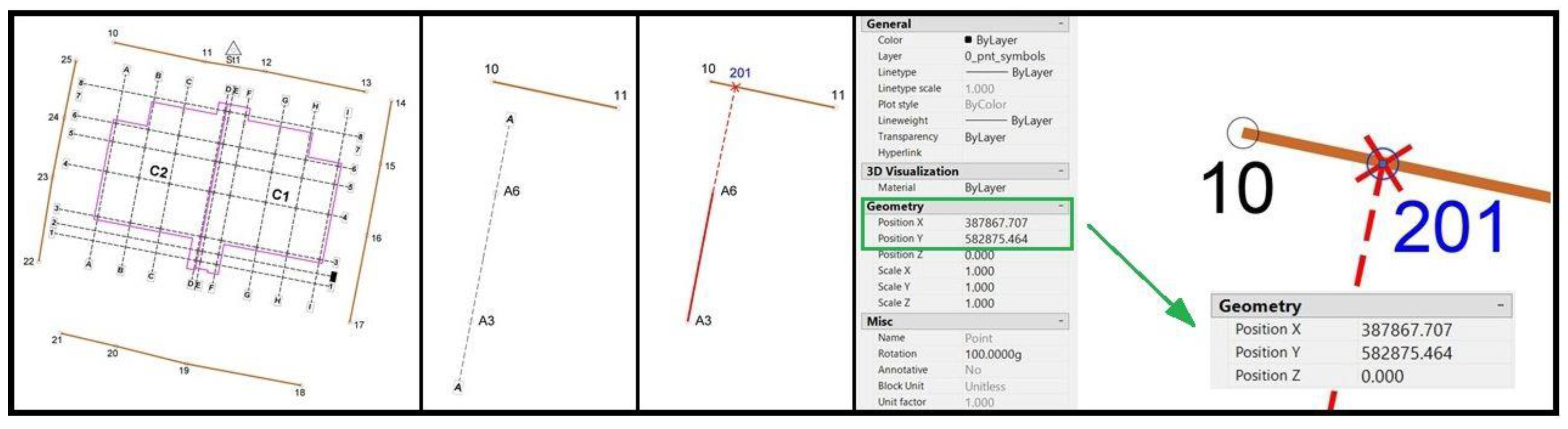
The planning of the layout process is one of the most important tasks for the survey engineer. This layout ensures the horizontal and vertical geometries of the engineering structure, and takes into account the instrumentation and the required accuracies previously mentioned. The established site layout plan is compiled using the cumulative cadastral information, land survey, building permit and design plans of the construction. A comprehensive design must highlight the layout of the proposed construction inside the terrain, as well as the inclusion of the coordinates and the calculated layout elements of the building reference points. The stake-out elements consist of horizontal angles and distances from known geodetic points or control points and, although total stations are capable of coordinate geometry calculation (COGO functions), the site layout plan should incorporate these values in order to carry out the on-site project regardless of the instrumentation. This is because many construction companies or construction survey engineers use electronic theodolites such as the Leica Builder series, which are reliable instrumentations that measure angles and distances, but do not have the processing power and the functions of coordinate geometry calculation. Thus, a comprehensive site layout plan (
Figure 5) should include all the information necessary to layout the designed structure (the extracted coordinates of each construction layout point and the stake-out horizontal angle and distance from the station points).
In order to obtain an automation of the calculations of horizontal angles and distances, a spreadsheet type software can be used. The measured (geodetic network/control points) and the designed coordinates (construction layout points/axes intersections) are extracted from the CAD platform and exported in the spreadsheet. The calculus is similar to that presented in
Section 2.4, with the following formulas used:
2.6. Batter Boards Importance and Layout Lines Marking Methods
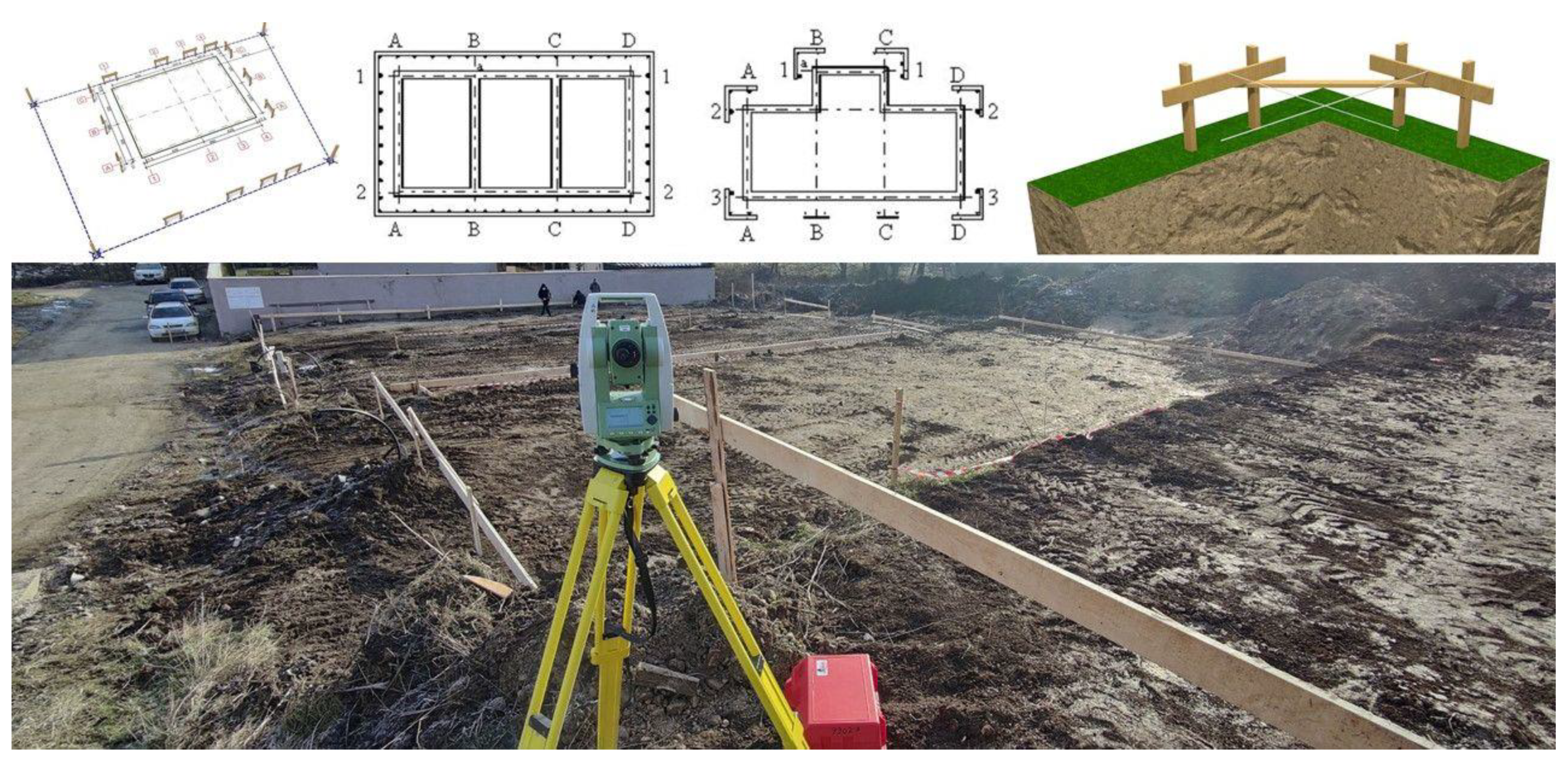
Batter boards are temporary wooden frameworks constructed and displayed around the in-site layout, used to suspend the layout strings for a foundation or a structural element from the ground floor. Their placement is crucial for building with the correct designed geometries. Batter boards consist of two vertical wood poles and a horizontal crosspiece screwed to the verticals (
Figure 6). The height of the boards must be over the height of the finish floor elevation, and if possible, all horizontal crosspieces must have the same elevation. Batter boards are commonly set beyond the corners of a planned foundation, but they can also be continuous and cover the whole perimeter of the construction [
1,
4]. These batter boards are then used in order to layout or stake-out on them the axes of the construction, and by intersecting construction twine between two axes to indicate the precise location of a construction layout point.
Batter boards are very popular for small to medium scale construction sites. Survey engineers commonly use them in order to layout the construction axes, in order for the builder to further determine construction layout point without the help of instrumentation or survey expertise. This practice can be applied for smaller scale construction sites, because the intersection of construction twine in order to determine a layout point can be achieved for the foundation and the structural elements on the ground floor (columns, beams, load-bearing walls). This is because the elevation of the batter boards is usually at one meter above ground level, and it would be impossible to use them on an upper floor. Due to the high demand of construction survey and layout, the batter boards holding layout lines is a very popular solution [
1,
24].
There are several methods of axes layout on these wood structures, depending on the instrumentation used and the calculus capability of the user and apparatus. Thus, the present case study contains a novelty comparison between four methods of batter boards stake-out of the construction layout lines, in order to determine the most efficient way possible, as well as a comprehensive evaluation of the advantages and disadvantages of each method and the possible instrumentation used. The four methods consist of: the classical optical method using a theodolite; the survey of the batter boards with manual calculation of coordinate intersection between the wood plank and the construction axes; the survey of the batter boards with CAD implementation and extraction of coordinate intersection between the wood plank and the construction axes; reference line or layout line function of the total station. These four methods will be further presented and evaluated in the next chapter, with a dissemination of the results, discussion and concluding remarks.


