Article

Preparation and Electron-Beam Surface Modification of Novel TiNi Material for Medical Applications

by
Sergey G. Anikeev
1,*,
Anastasiia V. Shabalina
1,
Sergei A. Kulinich
2,3,
Nadezhda V. Artyukhova
1,
Daria R. Korsakova
1,
Evgeny V. Yakovlev
4,
Vitaly A. Vlasov
5,
Oleg V. Kokorev
1 and
Valentina N. Hodorenko
1
1
Siberian Physical-Technical Institute, National Research Tomsk State University, 634050 Tomsk, Russia
2
Research Institute of Science and Technology, Tokai University, Kanagawa 259-1292, Japan
3
School of Natural Sciences, Far Eastern Federal University, 690091 Vladivostok, Russia
4
Tomsk Scientific Center, Siberian Branch of Russian Academy of Sciences, 634055 Tomsk, Russia
5
Research School of High-Energy Physics, National Research Tomsk Polytechnic University, 634050 Tomsk, Russia
*
Author to whom correspondence should be addressed.
Appl. Sci. 2021, 11(10), 4372; https://doi.org/10.3390/app11104372
Submission received: 3 April 2021 / Revised: 29 April 2021 / Accepted: 5 May 2021 / Published: 12 May 2021
(This article belongs to the Section Materials Science and Engineering)

Abstract

:

Featured Application

Materials and coatings for medical applications.

Abstract

A new approach to fabricate TiNi surfaces combining the advantages of both monolithic and porous materials for implants is used in this work. New materials were obtained by depositing a porous TiNi powder onto monolithic TiNi plates followed by sintering at 1200 °C. Then, further modification of the material surface with a high-current-pulsed electron beam (HCPEB) was carried out. Three materials obtained (one after sintering and two after subsequent beam treatment by 30 pulses with different pulse energy) were studied by XRD, SEM, EDX, surface profilometry, and by means of electrochemical measurements, including OCP and EIS. Structural and compositional changes caused by HCPEB treatment were investigated. Surface properties of the samples during their storage in saline for 10 days were studied and a model experiment with cell growth (MCF-7) was carried out for the unmodified sample with an electron beam to detect cell appearance on different surface locations.

1. Introduction

Titanium nickelide (TiNi) alloys are well-known to exhibit various attractive properties [1], such as resistance to corrosion, biocompatibility, shape memory effect, superelasticity, excellent mechanical performance, and so on [2,3,4]. As such, they are extensively studied and applied in numerous fields of science and engineering, including even such unconventional and new for them areas as supercapacitors [5], sensors and actuators [6] and endodontic instruments [7].
Of special importance is the use of TiNi based alloys in medicine for implant development. Monolithic TiNi materials were reported to exhibit excellent mechanical characteristics required of implanted structures. However, their smooth surface does not allow for fast and efficient attachment and growth of cells [8]. In addition, Ni ion release from the unprotected surface into leaving organisms was found and considered undesirable [9]. On the other hand, porous structures with a controllably modified surface, while inhibiting corrosion and reducing Ni ion release, were found not to provide mechanical performance at a satisfactory level. That is why new approaches that permit to fabricate TiNi surfaces combining the advantages of both monolithic and porous materials are still highly anticipated.
This explains why the development of TiNi-based materials for implants became increasingly active with the appearance of surface-treatment methods that use concentrated energy flows [10,11,12]. Providing more precise surface morphology control, such techniques permit to obtain surfaces that are more suitable for in vivo applications [13,14]. Materials based on TiNi alloys fabricated via more conventional methods such as powder metallurgy [15,16] (including, hot-press sintering [17], spark plasma sintering (SPS) [18,19,20], etc.), can be further modified using ion-plasma [21,22], ion-beam [23,24], laser-beam [25,26,27] or other similar treatments.
Among such methods, the low-energy high-current pulsed electron beam (HCPEB) seems to be one of the most promising techniques for surface modification of TiNi-based materials [28]. Importantly, HCPEB allows for homogenization of the surface layer through the dissolution of secondary-phase particles subjected to high-energy electron flow. As a result, this leads to enhanced corrosive stability of treated surfaces when they are placed into an environment characteristic of living cells [29]. Furthermore, HCPEB may increase the surface area of treated monolithic material, which should also enhance its integration in vivo.
In our previous work, we studied a TiNi powder obtained via the hydride-calcium reduction method [30]. The powder was shown to consist of irregularly-shaped particles with a well-developed microscopic surface [30]. In the present study, for the first time, a new material was designed and fabricated by depositing the above-mentioned porous powder onto monolithic TiNi plates followed by modification with HCPEB. The work aimed at preparing and modifying the material and investigating the changes caused by the HCPEB processing in surface morphology and composition. Both untreated and HCPEB-processed surfaces were then tested in terms of their interaction with saline, and first experiments on living cell growth were carried out.

2. Materials and Methods

2.1. Chemicals

The following chemically pure chemicals were obtained from Merck (Germany) and used as received: CaCl2, Fe(NO3)3 × 9 H2O, KCl, MgSO4 × 7 H2O, NaCl, NaH2PO4 × H2O, NaHCO3, HNO3, and HF. All their solutions were prepared using distilled water.

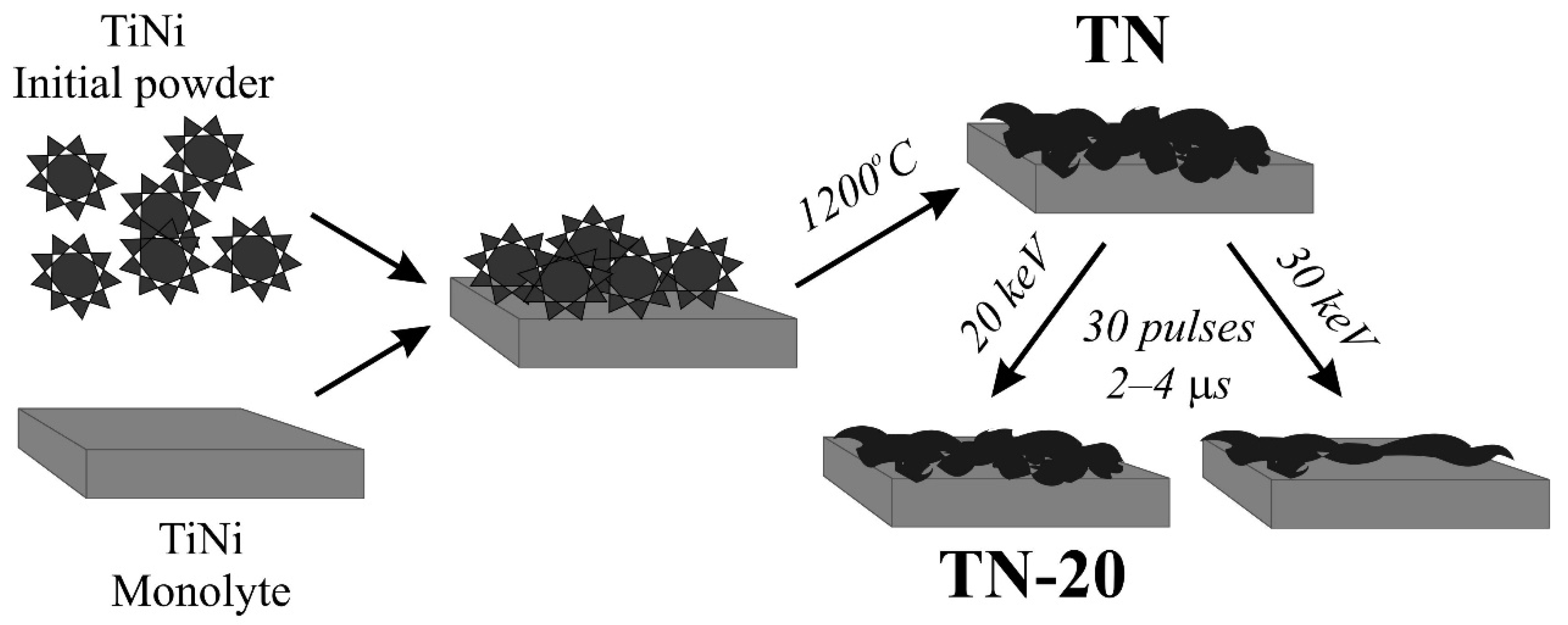
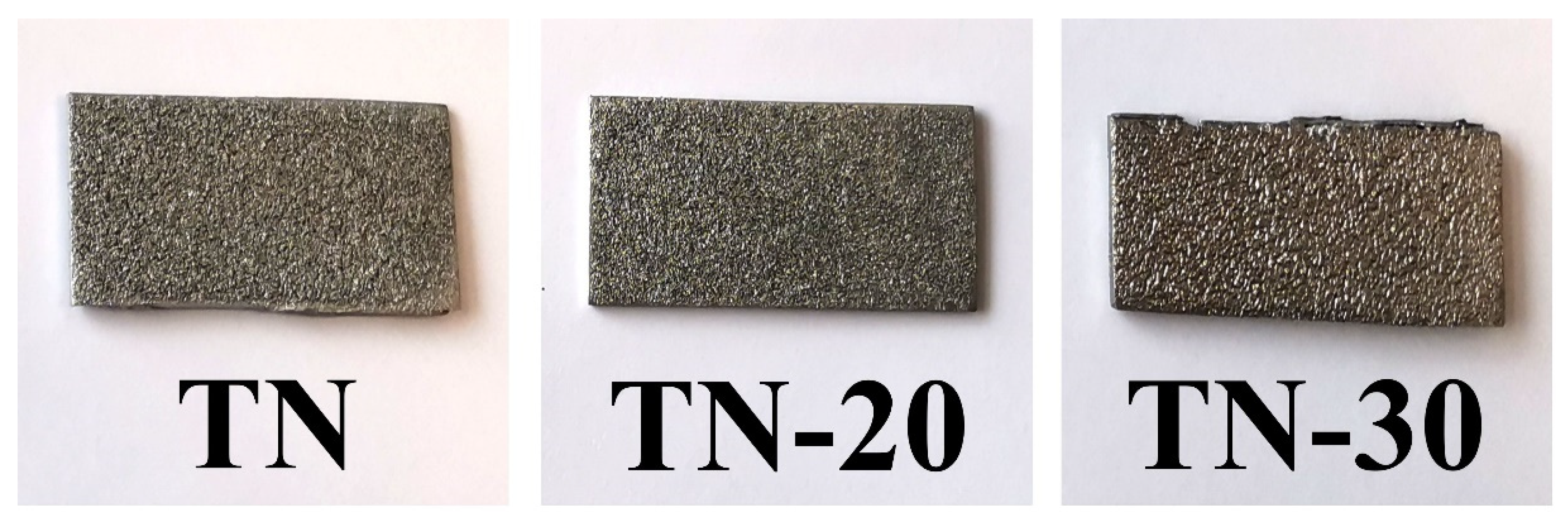
2.2. Sample Preparation

The samples studied in this work were all prepared via forming a coating of TiNi powder on monolithic TiNi substrates (from LLC Research and Production Enterprise “MITs”, Russia). The powder was obtained via the hydride-calcium reduction method, as was previously described elsewhere [30]. Degreased and cleaned plates of TiNi monolith were first covered with the initial TiNi powder by means of the filling method, forming a layer with a thickness of around 100–200 µm (Scheme 1), after which the samples were sintered in air at 1200 °C for 15 min to improve the contact of particles with both the substrate and each other.
As a result of sintering, sample TN was obtained (Scheme 1). The other two samples were subjected to additional treatment by an electron-beam performed with a RITM-SP station (Microsplav Inc., Tomsk, Russia), as previously described by Markov and co-authors [31]. The station is capable of generating electron beams with low energy (10–30 keV) and high current (up to 25 kA) with a pulse duration of 2–4 µs and diameters up to 80 mm. To process samples, in this study a beam with the energy of 20 and 30 keV was used, which generated energy density about 3 and 6 J/cm2, respectively. Sample TN-20 was obtained after processing sample TN with 30 pulses at 20 keV, while the sample TN-30 underwent a treatment of 30 pulses with 30 keV (see Scheme 1).

2.3. Sample Characterization

X-ray diffraction (XRD) patterns of the samples were obtained by means of XRD 6000 (Shimadzu, Japan) and ARL X’TRA (Thermo Fisher Scientific, Switzerland) diffractometers. The patterns were recorded within the range of 2θ = 20–100° at a rate of 0.02°/s using CuKα radiation. For phase analysis, the PDF-4 database and Powder Cell 2.5 software with pseudo-Voigt profile function were then used.
Scanning electron microscopy (SEM) studies were performed in either secondary electron mode (SE) or back-scattered electron mode (BSE, z-contrast) using a Quanta 200 3D system (FEI Company, Hillsboro, OR, USA). Cross-sectional specimens were prepared via polymerizing the samples in epoxy resin followed by electrical discharge machining (ARTA 123 PRO, SIC Delta-Test, Moscow Region, Russia). The sections were polished and etched using aqueous HNO3 and HF, and finally coated with a 10-nm-thick Au film (Sputter Coater Module SPI-Module™, SPI Supplies, West Chester, RA, USA) for SEM imaging.
Surface roughness parameters (maximum deviation Rz and average roughness Ra) were obtained by means of an interference microscope-profilometer MNP-1 (Technological Design Institute of Scientific Instrument Engineering, the Siberian Branch of RAS, Russia) and its original software.

2.4. Electrochemical Measurements

For electrochemical measurements, the obtained materials were first cut into pieces with sizes of 4 × 4 × 2 mm3, and then their backside was connected to copper wires and insulated by non-conductive polish so that only their surface with TiNi coating was involved into contact with testing solution.
Electrochemical measurements were carried out using an electrochemical workstation CH-660D (CH Instruments, Austin, TX, USA). A three-electrode cell with an Ag/AgCl (1 M KCl) reference electrode and a platinum wire spiral auxiliary electrode was used. Saline solution containing 7 salts (an inorganic fraction of DMEM, see Section 2.5 below) was used as the electrolyte without degassing. Open circuit potential (OCP, EOC) was measured for at least 1 h (or more) to obtain a stable value (±5 mV). Electrochemical impedance spectra (EIS) were recorded at the open circuit potential with an amplitude of 0.01 V, while frequency was varied within the range 1–100,000 Hz. The EIS data were then processed using the ZView software (Scribner Associates, Inc., Southern Pines, NC, USA). From three to five parallels were performed and the results were averaged.

2.5. Cell Growth Experiment

Michigan Cancer Foundation-7 (MCF-7) cells, which are a breast cancer cell line obtained from Tomsk National Research Medical Center of the Russian Academy of Sciences, were used. For experiments, pieces of sample TN (prepared for further electrochemical measurements according to Section 2.4.) were covered with the cells and immersed into a medium containing Dulbecco’s Modified Eagle Medium (DMEM) with 10% fetal bovine serum (FBS), antibiotics (100 U/mL penicillin and 100 mg/mL streptomycin) and 2 mM of L-glutamine (from PanEco Company, Moscow, Russia). Cell cultivation was performed at 37 °C in a humidified room in an atmosphere with 5% CO2 for 1, 3, and 5 days for electrochemical measurements, and for one week for microscopic studies. From three to five parallels were performed and the results were averaged.
The 3D reconstructed image of cells on the sample surface was obtained without sample drying using confocal laser scanning microscopy (CLSM, LSM 780 NLO tool from Zeiss, Jena, Germany) in z-stack mode.

3. Results and Discussion

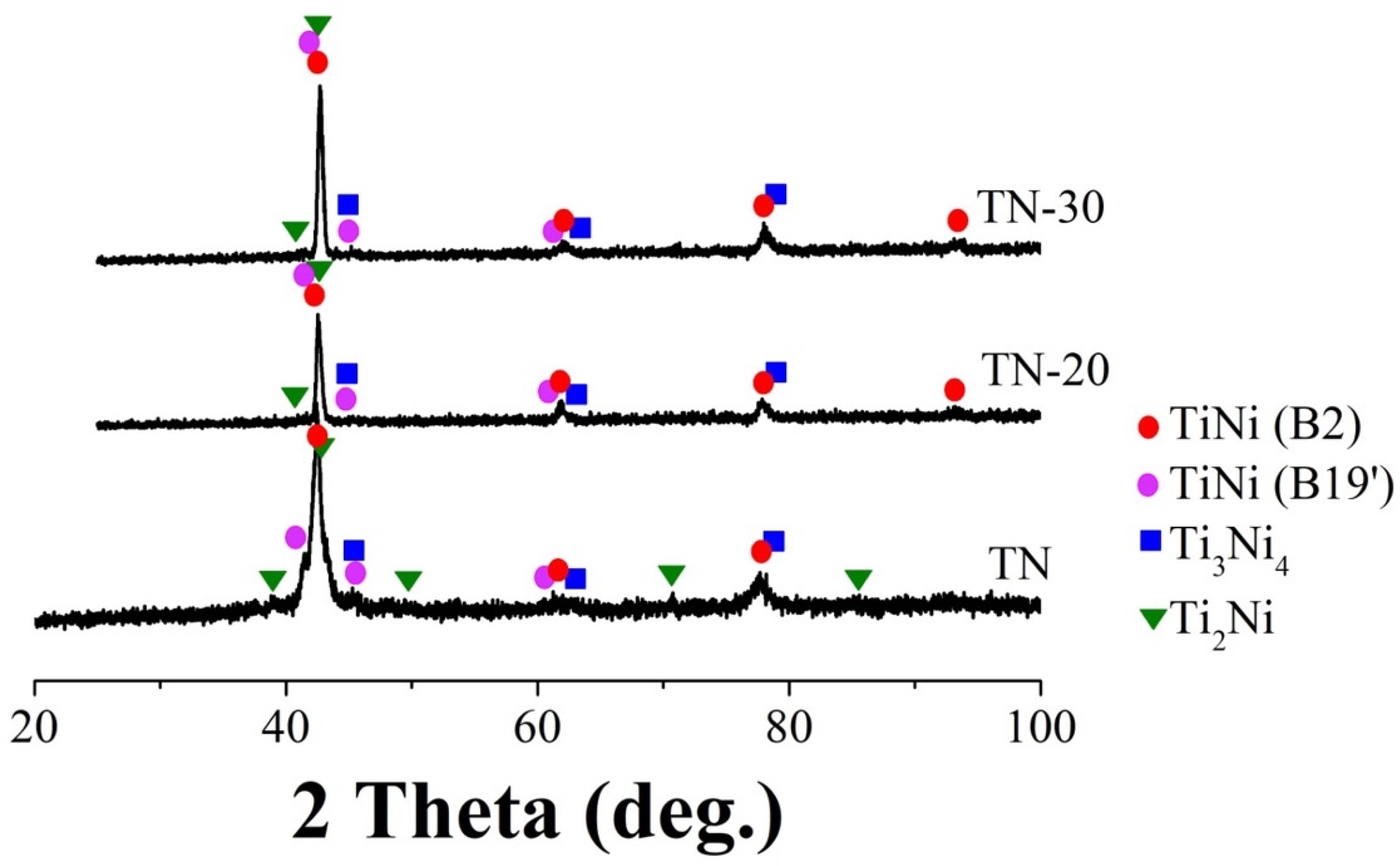
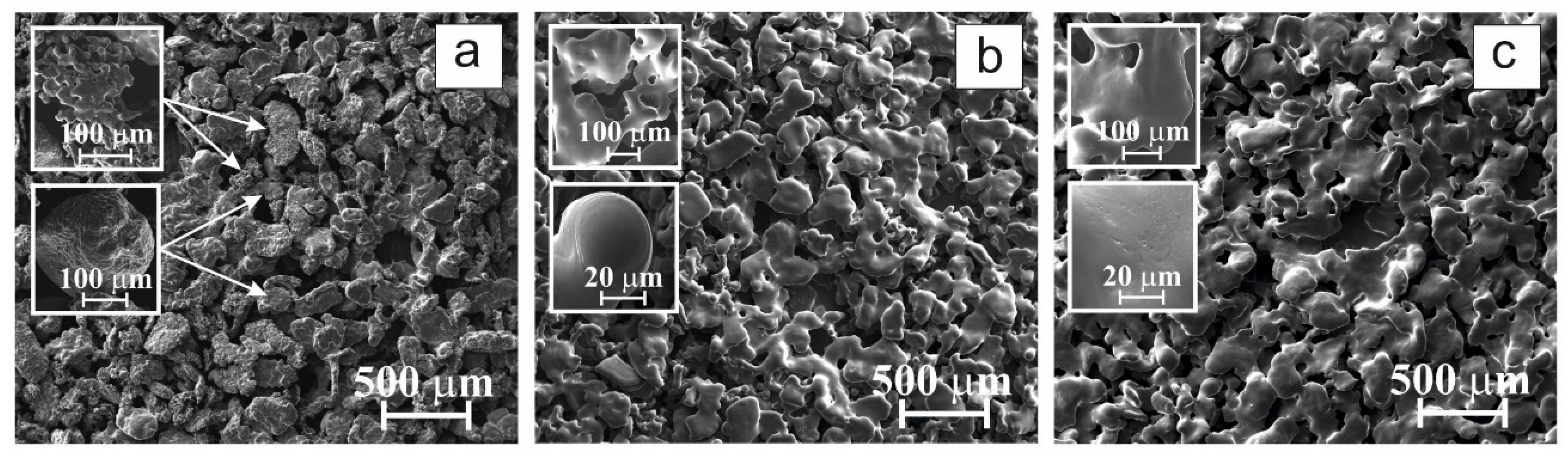
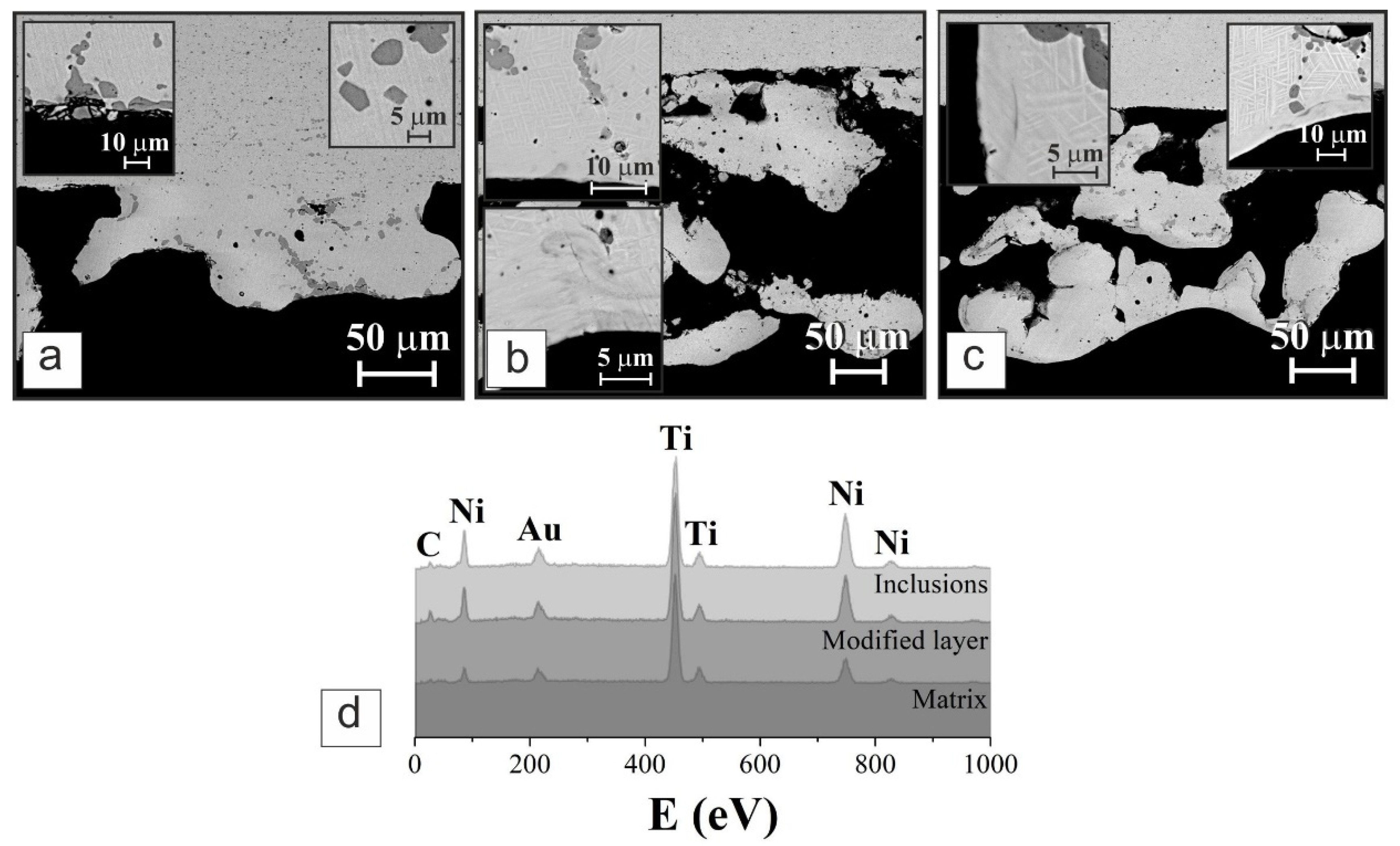
3.1. Structure and Composition

As previously described [30], the initial powder represented with particles of 100–200 µm had two types of surface morphology, i.e., sponge-like and compact types. The particles of the former type were found to consist primarily of TiNi phase, while the latter compact particles contained large TiNi grains surrounded with Ti2Ni phase [30].
As a first preparation step, initial TiNi powder was placed onto a TiNi monolithic plate surface and thermally treated to form a porous coating (Scheme 1). During this stage, because of high temperature, the powder particles formed contact zones that prevented any motion of the latter particles when the samples were further processed by HCPEB. The photographs of prepared samples are presented in Figure 1.
The phase composition of two HCPEB-treated samples (TN-20 and TN-30), as well as that of their non-treated counterpart (TN), was studied by the XRD method. The results presented as patterns in Figure 2 revealed that all three samples contained the following phases: TiNi (phases B2 and B19′ with PDF-4 cards 01-076-3614 and 01-078-2550, respectively), Ti3Ni4 (PDF-4 card 04-001-1903), and Ti2Ni (PDF-4 card 04-007-1531). This finding implies that the pulse electron beam treatment applied in this work did not affect the composition of phases within the formed surface layer, but rather influenced fractions of such phases (see Table 1). For both treated samples TN-20 and TN-30, their TiNi content increased, while that of Ti2Ni decreased when compared with untreated sample TN.
Interestingly, whereas in sample TN-20 the fraction of phase Ti3Ni4 dropped to 7 wt%, its content was again back to 14 wt% in sample TN-30, as more energy was applied (Table 1). It is possible that the phase evolution observed in sample TN-30 could be caused by material aging due to additional heating under more energetic HCPEB, which is known to be associated with formation of phase Ti3Ni4 [3]. Indeed, since sample TN-30 was subjected to more intense high-energy impact, its top-layer could be more prone to aging and precipitation of phase Ti3Ni4.
Figure 3 presents SEM images of sample surfaces, with insets depicting more details at higher magnification. Sample TN is seen in Figure 3a to inherit the morphology of initial powder, containing two types of particles, sponge-like and compact ones (presented as insets and indicated with arrows in Figure 3a). The average roughness (Ra) was evaluated for this material to be around 80 µm (Table 2). HCPEB treatment with 20 keV is seen in Figure 3b to result in surface smoothening and homogenization, which is also confirmed by roughness measurements (see Table 2). It was expected that HCPEB treatment would cause some smoothening of single particles, as well as filling of cracks and pores on the surface. The high-energy beam led to surface melting of TiNi particles, also increasing their contact areas and giving rise to newly recrystallized surface layers forming upon cooling down. In agreement with surface smoothening observed in Figure 3b, the average roughness of sample TN-20 was found to decrease by 12.5% (Table 2).
HCPEB treatment with higher energy of the material is seen in Figure 3c to result in further surface smoothening and homogenization. The size of surface features further increased and the average roughness of sample TN-30 decreased by 25% when compared with that of sample TN (Table 2).
The changes occurring in the surface layer during HCPEB treatment are also presented in cross-sectional BSE images of the samples (Figure 4). In all panels of Figure 4, the matrix of materials consisting of TiNi (phase B2) incorporates small crystallites of Ti3Ni4 which are not seen in the figure but were confirmed by XRD and well-known from the literature [32]. As a result of their distribution in the B2 matrix, internal stresses appear inside the particles of the coating [32,33]. These stresses are known to originate from the parameter mismatch between the crystal lattice of small Ti3Ni4 crystallites and the TiNi B2 matrix. In addition, the Ti3Ni4 phase is not prone to martensitic transformations [34], which also contributes to stresses inside the material.
The stresses inside phase B2 eventually cause its transformation to phase B19′ with a packed-pyramidal morphology, which is seen as light lines inside the TiNi matrix (Figure 4 and insets therein). Thus, the cross-sections of obtained materials are characterized by disoriented martensitic relief. Finally, the dark-grey spots seen as inclusions into the TiNi matrix in Figure 4 indicate the presence of phase Ti2Ni, which is confirmed by EDX data (Figure 4d, Table 3).
After HCPEB treatment, a recrystallized layer appeared on the topmost surface of both samples TN-20 and TN-30 (insets in Figure 4b,c). This layer is seen in insets (Figure 4b,c) not to contain inclusions of different phases and seems to be structurally homogeneous. Depending on the curvature, which differs at different locations of the coating, this recrystallized layer demonstrated varied thickness between 5 and 20 µm. Quite expectedly, this layer is seen to be generally thicker for sample TN-30, which was HCPEB-treated with higher energy beam.
According to EDX spectra taken at different locations of sample TN-30 and shown in Figure 4d, the modified layer is enriched with Ti (Table 3). This can be explained by melting of Ti2Ni (inclusions in spectra and Table 3) at high temperatures caused by HCPEB and its further dissolution in the matrix (see Table 1). This observation is well consistent with works by others where homogenization of surface layer atop monolith materials based on TiNi caused by electron-beam processing was also reported [35,36,37,38].
Thus analysis of structure and composition of untreated sample TN and samples TN-20 and TN-30 processed with HCPEB permits to conclude that electron-beam treatment caused structural changes and phase redistribution in the surface layer of the materials. The roughness of HCPEB-treated samples decreased as much as up to 25%, and their modified top layer was as thick as 5–20 µm and enriched in Ti.

3.2. Electrochemical Tests and Cell Growth

For materials developed as implant components or coatings, their surface properties, and especially their behavior in contact with biological liquids (such as saline solutions) are of prime importance. That is why, upon preparation and surface characterization, the samples produced in this work were electrochemically tested. As mentioned above, contacts with copper wires were first provided, after which the substrate area of the samples was insulated, leaving only a coated surface available for contact with electrolyte. Thus prepared electrodes, together with counter and reference electrodes, were then immersed in a model saline solution (inorganic fraction of DMEM) and connected to electrochemical system.
First, the open circuit potential (OCP or EOC) which characterizes processes taking place on the surface immersed in a solution was measured. The OCP shows how the material undergoes corrosion in the medium in which it is immersed. Second, electrochemical impedance spectroscopy (EIS) was applied to comprehend possible mechanisms involved into electrochemical processes. To trace changes occurring over long-term contact with saline, both OCP and EIS were monitored for the same samples stored in saline for 1, 3, 5, 7 and 10 days. The results are presented and discussed in the following section.

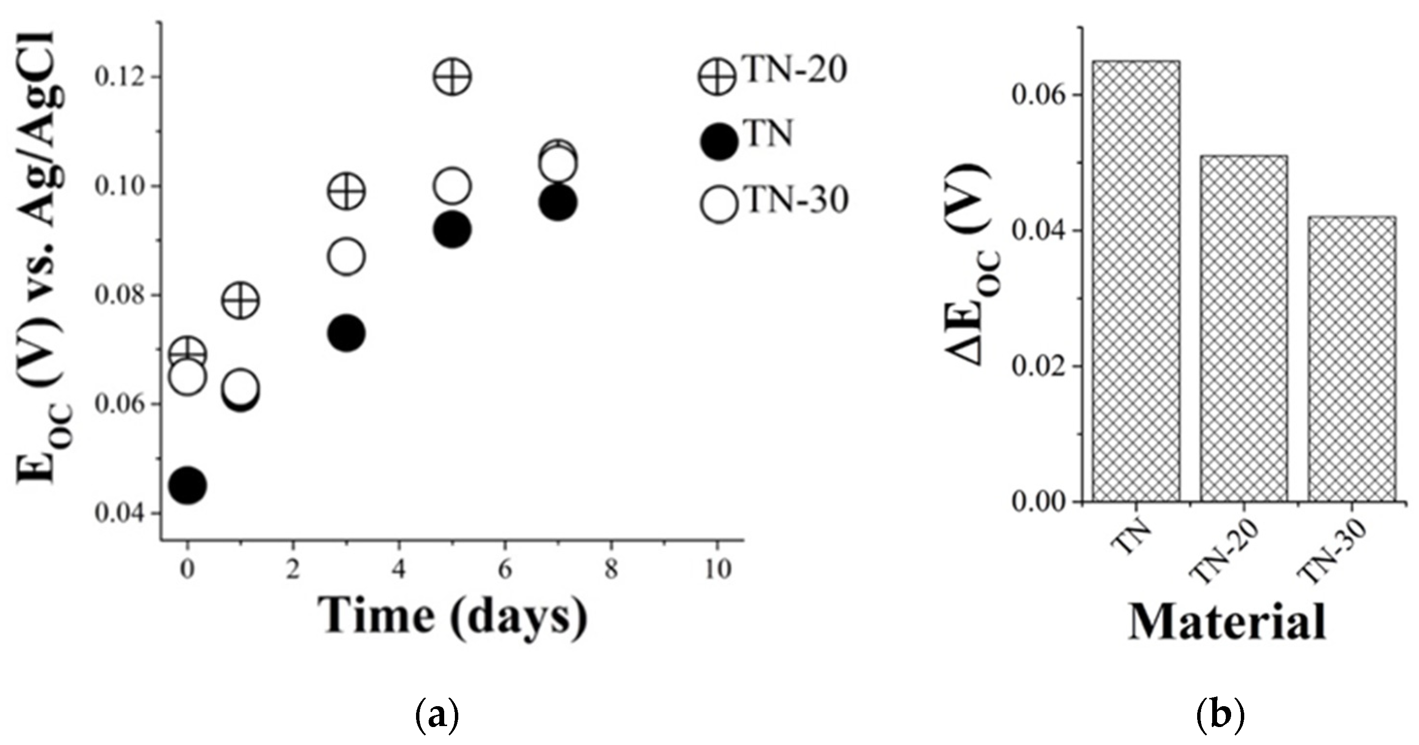
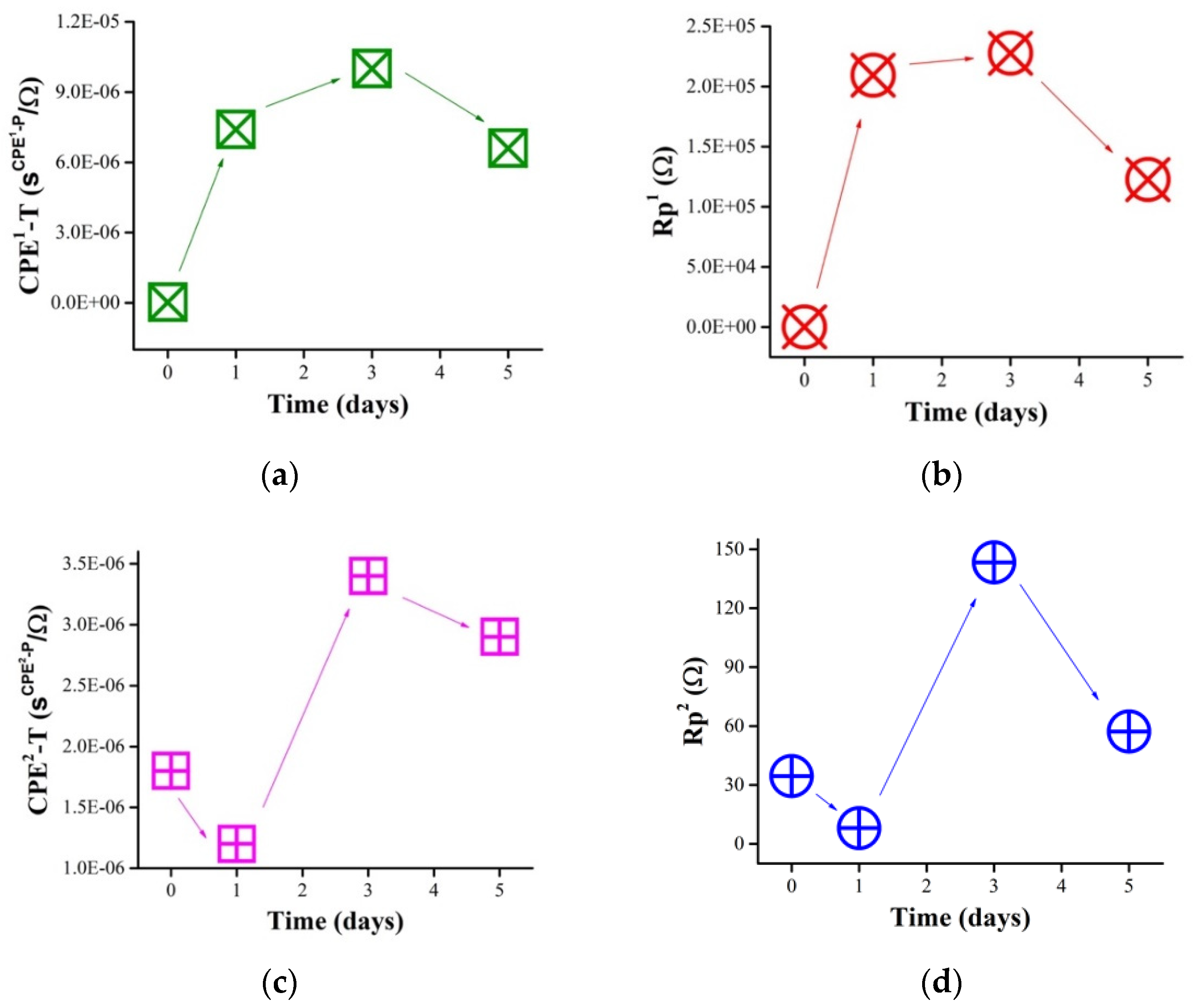
3.2.1. Effect of Saline Medium on Samples
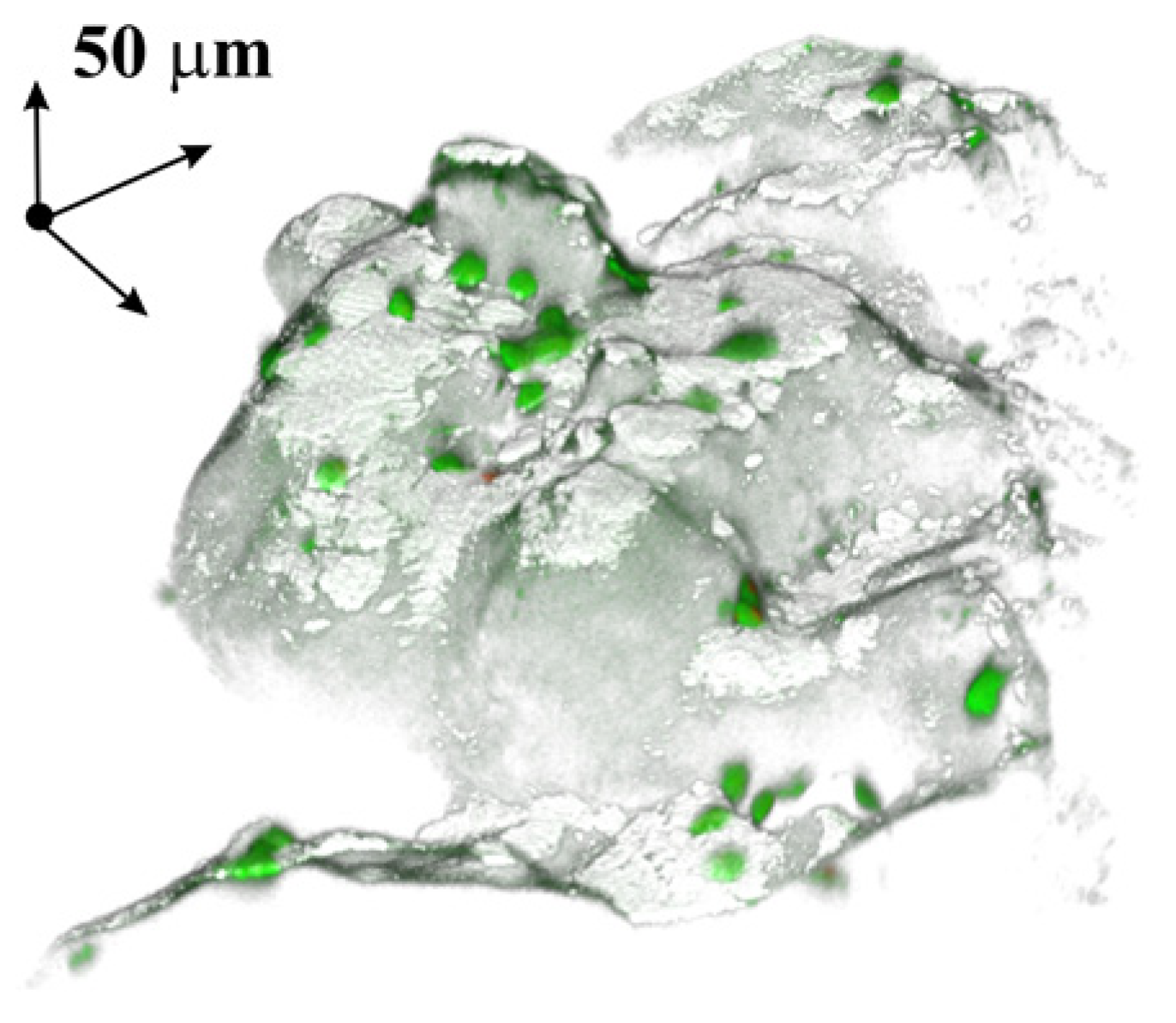
It is seen in Figure 5a that the initial OCP value for sample TN was the lowest of all the tested samples (black solid circles), while both HCPEB-modified materials exhibited somewhat higher OCP values (open circles and crossed circles for TN-30 and TN-20, respectively). This implies that HCPEB treatment increases the material’s resistance against corrosion in saline environment. The EOC values observed for HCPEB-modified TN-20 and TN-30 were slightly different, which could be related to their different phase composition (Section 3.1).
Storage in saline environment for 10 days is seen in Figure 5a to lead to a steady increase in OCP values for all the samples. The highest value was exhibited by sample TN-20, but the smallest overall increment was demonstrated by sample TN-30, implying that increased beam energy during HCPEB treatment had a positive effect on the stability of formed TiNi coatings (Figure 5b). This can be explained by a thicker modified topmost layer observed for sample TN-30 in comparison with TN-20, since this layer is believed to block corrosive processes. Thus, the stability of the surface properties of the three samples in contact with saline was found to increase within the row: TN < TN-20 < TN-30.
EIS data were recorded in a three-electrode cell filled with the same saline solution, and a typical experimental Nyquist plot is presented in Figure 6a. Results of ZView simulation and a corresponding equivalent circuit are also presented in Figure 6. Note that all the samples prepared in this study showed similar Nyquist plots, which is why Figure 6a only presents data obtained for sample TN-30, while all values of simulation parameters calculated for each sample can be found in Supplementary Materials Table S1.
The equivalent circuit exhibited in Figure 6b consists of two parts, which is why the processes on the surface of tested samples are characterized by two time constants. This is consistent with the earlier described model for a double-layered structure of a passive film on a TiNi surface [39]. For comparison, another group used a simpler equivalent circuit (with one time constant) to describe their TiNi presented as a thin film [40].
Based on the above discussed SEM results, we suggested that the first part of the equivalent circuit (parallel elements CPE1 and Rp1) with the relaxation time of 10−6–10−7 s (Table 4) represents the outer layer of the coating and surface of open shallow pores. Meanwhile, the second part (a part of a simplified Randles cell, CPE2, Rp2 and W) with its relaxation time around 10−5 s, was ascribed to the more difficult-to-reach surface of deep and/or difficult-to-permeate pores and the monolithic TiNi sublayer that remained uncovered with the particle-based coating. For simplicity, hereafter they will be referred to as the ‘external’ (first part in Figure 6b) and ‘internal’ (second part in Figure 6b) layers of the material.
Comparing the CPE-T and Rp values of the two parts (see Table S1), one can see that the CPE1-T parameter is much lower than CPE2-T, whereas Rp1 is larger than Rp2. This is well consistent with the assumption about the external and internal layers. As the internal layer has a larger surface area, its capacitive parameter should be higher. At the same time, its resistance to corrosion is lower because this part of the coating was less exposed to HCPEB treatment (lower access to deeper layers). Vice versa, the external part of the coating is better protected from the corrosion (exhibiting higher Rp values) since its modified layer was enriched in Ti and is normally covered with a very thin TiOx film [28] (see Section 3.1). As for its capacitance, it is smaller as a result of a lower surface area of the external layer of the material.
As can be seen in Table S1, all the parameters remained within one order of magnitude during all the period when the materials were immersed in saline medium. This implies no dramatic changes of surface properties were observed for as long as ten days. Even parameter Rp1, which is attributed to the overall corrosion resistance of the material, did not change significantly. However, the second component of the circuit, which reveals behavior of the internal layer, was found to show steady changes in parameter Rp2 (see Figure 7).
The resistance of the internal layer is seen in Figure 7 to decrease steadily for sample TN over immersion time. It also decreased for sample TN-30, although to a smaller extent. For sample TN-20, however, after 10 days its Rp2 was found to be very close to its initial value. Note that after exposure to saline for 10 days, the Rp2 value observed for sample TN-20 is the highest resistance of all the samples tested (see crossed circles in Figure 7). Since parameter Rp2 is a characteristic of a deep-pore surface and that of uncoated TiNi monolith substrate, sample TN-20 seemed to have this component of its surface better protected against corrosion. This could be related to the difference in phase content of this material in comparison with the other two samples (the highest content of TiNi and the lowest of Ti3Ni4 and Ti2Ni phases).
Paying attention to the lifetime parameters presented in Table S2, one finds that, in general, the processes occurring in the external layer (first part of the circuit) proceeded faster than those in the internal layer (second part of the circuit). This is reasonable as the internal layer is more difficult to access for electrolyte. The lowest values of τ1, implying the fastest rates of surface processes in comparison with the other samples, are observed for sample TN-20. Similar to the above discussion for parameter Rp2, this could be also related to the highest content of TiNi and the lowest contents of phases Ti3Ni4 and Ti2Ni on this sample.
Thus, our electrochemical studies revealed that HCPEB-modified TiNi coatings increased their stability against corrosion. Interaction of such materials with saline can be described by a two-component model: faster interaction of the electrolyte with the easier accessible external layer of the coating and slower interaction with the more difficult-to-access internal layer consisting of a deep-pore surface and a monolithic TiNi sublayer. The latter internal layer is less protected against corrosion, but the HCPEB treatment increased its resistance, especially for sample TN-20 modified by electron beam with 20 keV.

3.2.2. Cell Growth

The preliminary experiment with the model cell growth was conducted on the surface of sample TN. It is seen in Figure 8 that the breast cancer cells partially covered the material surface after a week of cultivation. They can be seen all across the entire surface both as single objects and as small groups. However, the observed surface belongs to the external layer of the material, while the cells possibly grown in the internal layer could not be visualized. To detect the existence of such cells in the hidden region, we compared EIS data obtained in saline for both cell-free samples and those with cells cultivated for 1, 3, and 5 days. Interestingly, the samples populated with cells demonstrated impedance spectra similar to their cell-free counterparts whose typical Nyquist plot was previously shown in Figure 6. Therefore, the same equivalent circuit can be used to describe processes occurring on the surfaces with grown cells. Thus, the presence of growing cells appears not to affect the mechanism of surface processes in saline medium. At the same time, the values of CPE-T and Rp parameters were found to change over time of cell growth, as shown in Figure 9.
The parameters associated with the external layer of the sample (CPE1-T and Rp1) are seen in Figure 9a,b to demonstrate the most dramatic change after as long as just one day of cell growth. Meanwhile, the parameters describing the internal layer (CPE2-T and Rp2) are seen to undergo the most noticeable change between days 1 and 3 of cell cultivation (Figure 9c,d). Since cells are non-conductive biological objects, both layers were expected to increase resistance in their presence. Therefore, the observed drastic increase of parameters Rp1 and Rp2 is a good indication of cell growth on both the external and internal layers of the sample. Since the internal surface was harder to reach for cells, its resistance (Rp2) is seen in Figure 9 to jump later than Rp1. Note that both CPE-T parameters demonstrated behavior similar to that of their corresponding Rp parameters, from which we conclude that the presence of cells somehow resulted in increase of both capacitive components CPE1-T and CPE2-T.
As seen in Table 4, time constants τ1 and τ2 also demonstrated drastic changes between days 0–1 and 1–3, respectively. The lifetime τ1 associated with processes in the external layer of the coating increased by 6 orders of magnitude, and τ2, related to the internal layer, increased by two orders of magnitude. Hence, the presence of cells was found to slow down surface processes. That is why, through the changes of parameters Rp, CPE and τ, analysis of EIS data allowed us to observe the appearance and growth of cells on both external and internal layers of the coatings prepared in this study.
Eventually, after 5 days of cell cultivation, the CPE-T and Rp parameters of both parts of the circuit (as well as parameter τ1) somewhat decreased, as well seen in Figure 9. This could be due to possible stabilization of the system TiNi/cells. For deeper understanding, additional and more detailed studies are needed, which was not within the scope of the present work.
Thus, using electrochemical techniques it was found that cell growth first begins on the external surface, after which cells start covering the deeper layer of the material by day three of cultivation experiments. Hence, using this relatively simple and easy approach, kinetic studies of cell growth can be realized in the future. It should be noted that this proposed approach based on EIS data analysis of rough surfaces with cells cultivated on them is only applicable to materials that can be described by means of two-component equivalent circuit, similar to those developed in this work.
After testing cell growth on sample TN, it was concluded that the cell culture used (MCF-7) was not an appropriate model object for implants, which is why the other two samples were not tested in terms of cell growth. Nevertheless, since EIS measurements and their analysis showed promise as a simple approach to detect cell growth in deep pores of a rough sample, we decided to report our results here. Meanwhile, more appropriate cells should be tested on the TiNi materials newly developed in this study to evaluate their suitability for medical applications.

4. Conclusions

For the first time, new materials were obtained by depositing a porous TiNi powder onto monolithic TiNi plates followed by sintering at 1200 °C and further modification with high-current-pulsed electron beam (HCPEB) treatment. Analysis of the structure and composition of newly developed materials showed that the treatment caused structural changes and phase redistribution in the HCPEB-processed surface layer. Depending on the energy of applied electron beam, the modified top layer of the coatings was found to be of 5–20 µm and enriched in Ti, while their overall roughness decreased up to 25%.
As potential materials for medical applications (as implants), the prepared samples were then tested electrochemically during their storage in saline and after cell cultivation on one of them. Simulation of obtained impedance data resulted in a model with two layers (external and internal) which was valid for all the samples. The external layer consisted of the topmost surface of coating and its shallow pores, whereas the internal layer was assigned to deeper pores and the TiNi monolith sublayer. The tested cells, MCF-7, were found to grow first on the external layer, after which their growth was detected on the internal layer. The electrochemical studies also revealed increased stability of HCPEB-treated TiNi coatings against corrosion. The obtained results imply that the newly developed materials, consisting of TiNi porous coating on monolith TiNi plate and modified by HCPEB, can be promising for implant development.

Supplementary Materials

The following are available online at https://www.mdpi.com/article/10.3390/app11104372/s1, Table S1: Values of CPE-T and Rp parameters calculated from EIS data for materials before and after immersion in saline (inorganic fraction of DMEM) from 1 to 10 days; Table S2: Time components values from EIS data for all samples.

Author Contributions

Conceptualization, S.G.A., A.V.S. and V.N.H.; methodology, V.N.H., O.V.K. and S.A.K.; investigation, N.V.A., O.V.K., E.V.Y., V.A.V. and D.R.K.; resources, E.V.Y., V.A.V. and V.N.H.; writing—original draft preparation, A.V.S., S.A.K., N.V.A., D.R.K. and S.G.A.; writing—review and editing, A.V.S. and S.A.K.; project administration, S.G.A. and V.N.H.; funding acquisition, S.G.A. All authors have read and agreed to the published version of the manuscript.

Funding

This research was funded by the Russian Science Foundation, grant number 19-79-10045.

Institutional Review Board Statement

Not applicable.

Informed Consent Statement

Not applicable.

Acknowledgments

Characterization was carried out using the equipment of the Tomsk Materials Science Shared Center of Tomsk State University.

Conflicts of Interest

The authors declare no conflict of interest.

References

  1. Buehler, W.J.; Gilfrich, J.W.; Wiley, R.C. Effect of low-temperature phase changes on the mechanical properties of alloys near composition TiNi. J. Appl. Phys. 1963, 34, 1475–1477. [Google Scholar] [CrossRef]
  2. Otsuka, K.; Ren, X. Physical metallurgy of Ti-Ni based shape memory alloys. Prog. Mater Sci. 2005, 50, 511–678. [Google Scholar] [CrossRef]
  3. Saburi, T. Ti-Ni shape memory alloys. In Shape Memory Materials; Otsuka, K., Waymann, C.M., Eds.; Cambridge University Press: Cambridge, UK, 1999; pp. 49–96. [Google Scholar]
  4. Parvizi, S.; Hashemi, S.M.; Asgarinia, F.; Nematollahi, M.; Elahinia, M. Effective parameters on the final properties of NiTi-based alloys manufactured by powder metallurgy methods: A review. Prog. Mater. Sci. 2021, 117, 100739. [Google Scholar] [CrossRef]
  5. Saber, O.; Ansari, S.A.; Alshoaibi, A. Development of Ti/Ni nanolayered structures to be a new candidate for energy storage applications. Appl. Sci. 2020, 10, 6935. [Google Scholar] [CrossRef]
  6. Jani, J.M.; Leary, M.; Subic, A.; Gibson, M.A. A review of shape memory alloy research, applications and opportunities. Mater. Des. 2014, 56, 1078–1113. [Google Scholar] [CrossRef]
  7. Carpegna, G.; Alovisi, M.; Salvatore Paolino, D.; Marchetti, A.; Gibello, U.; Scotti, N.; Pasqualini, D.; Scattina, A.; Chiandussi, G.; Berutti, E. Evaluation of pressure distribution against root canal walls of NiTi rotary instruments by finite element analysis. Appl. Sci. 2020, 10, 2981. [Google Scholar] [CrossRef]
  8. Bajt, A.; Krajnovic, A.; Lakota, K.; Zigon, P.; Sodin-Semrl, S.; Kralj-Iglic, V.; Iglic, A. The importance of antibacterial surfaces in biomedical applications. In Advances in Biomembranes and Lipid Self-Assembly; Iglic, A., Rappolt, M., Garcia-Saez, A.J., Eds.; Elsevier: Amsterdam, The Netherlands, 2018; Volume 28, pp. 115–165. [Google Scholar] [CrossRef]
  9. Shabalovskaya, S.; Anderegg, J.; Van Humbeeck, J. Critical overview of Nitinol surfaces and their modifications for medical applications. Acta Biomater. 2008, 4, 447–467. [Google Scholar] [CrossRef]
  10. Yan, X.J.; Gugel, H.; Huth, S.; Theisen, W. Microstructures and properties of laser cladding NiTi alloy with W for biomedical applications. Mater. Lett. 2011, 65, 2934–2936. [Google Scholar] [CrossRef]
  11. Zhu, S.L.; Yang, X.J.; Hu, F.; Deng, S.H.; Cui, Z.D. Processing of porous TiNi shape memory alloy from elemental powders by Ar-sintering. Mater. Lett. 2004, 58, 2369–2373. [Google Scholar] [CrossRef]
  12. Bartolo, P.J.; Bidanda, B. Bio-Materials and Prototyping Applications in Medicine; Springer Publishing: New York, NY, USA, 2008; 216p. [Google Scholar]
  13. Chua, C.K.; Leong, K.F.; Lim, C.S. Rapid Prototyping: Principles and Applications, 2nd ed.; World Scientific Publishing Co. Pte. Ltd.: Singapore, 2010; 540p. [Google Scholar]
  14. Shishkovsky, I.V.; Scherbakov, V.I.; Morozov, Y.G.; Kuznetsov, M.V.; Parkin, I.P. Surface laser sintering of exothermal powder compositions: The thermal and SEM/EDX study. J. Therm. Anal. Calorim. 2008, 91, 427–436. [Google Scholar] [CrossRef]
  15. Elsayed, A.; Umeda, J.; Kondoh, K. Effect of quenching media on the properties of TiNi shape memory alloys fabricated by powder metallurgy. J. Alloys Compd. 2020, 842, 155931. [Google Scholar] [CrossRef]
  16. Ma, X.; Wang, H.; Xie, H.; Qu, J.; Chen, X.; Chen, F.; Song, Q.; Yin, H. Engineering the porosity and superelastic behaviors of NiTi alloys prepared by an electro-assisted powder metallurgical route in molten salts. J. Alloys Compd. 2019, 794, 455–464. [Google Scholar] [CrossRef]
  17. Yi, X.; Wang, H.; Sun, K.; Gao, W.; Sun, B.; Shen, G.; Meng, X.; Gao, Z.; Cai, W. Characterization of high-strength Ti-Ni shape memory alloys prepared by hot pressed sintering. J. Alloys Compd. 2021, 854, 157159. [Google Scholar] [CrossRef]
  18. Nivala, P.T.; James, S.P. Master sintering curves of nickel-titanium and nickel-titanium open-cell foams fabricated by spark plasma sintering. J. Mater. Sci. 2019, 55, 3668–3683. [Google Scholar] [CrossRef]
  19. Samal, S.; Molnarova, O.; Prusa, F.; Kopecek, J.; Heller, L.; Sittner, P.; Skodova, M.; Abate, L.; Blanco, I. Net-shape NiTi shape memory alloy by spark plasma sintering method. Appl. Sci. 2021, 11, 1802. [Google Scholar] [CrossRef]
  20. Velmurugan, C.; Senthilkumar, V.; Biswas, K.; Yadav, S. Densification and microstructural evolution of spark plasma sintered NiTi shape memory alloy. Adv. Powder Technol. 2018, 29, 2456–2462. [Google Scholar] [CrossRef]
  21. Ju, X.; Dong, H. Plasma surface modification of NiTi shape memory alloy. Surf. Coat. Technol. 2006, 201, 1542–1547. [Google Scholar] [CrossRef]
  22. Witkowska, J.; Kaminski, J.; Płocinski, T.; Tarnowski, M.; Wierzchon, T. Corrosion resistance of NiTi shape memory alloy after hybrid surface treatment using low-temperature plasma. Vacuum 2017, 137, 92–96. [Google Scholar] [CrossRef]
  23. Rautray, T.R.; Narayanan, R.; Kim, K.-H. Ion implantation of titanium based biomaterials. Prog. Mater. Sci. 2011, 56, 1137–1177. [Google Scholar] [CrossRef] [Green Version]
  24. Levintant-Zayonts, N.; Kucharski, S. Surface characterization and wear behavior of ion implanted NiTi shape memory alloy. Vacuum 2009, 83, S220–S223. [Google Scholar] [CrossRef]
  25. Pequegnat, A.; Michael, A.; Wang, J.; Lian, K.; Zhou, Y.; Khan, M.I. Surface characterizations of laser modified biomedical grade NiTi shape memory alloys. Mater. Sci. Eng. C 2015, 50, 367–378. [Google Scholar] [CrossRef] [PubMed]
  26. Guo, W.; Sun, Z.; Yang, Y.; Wang, X.; Xiong, Z.; Li, Z.; Wang, C.; Cui, L.; Huang, S.; Li, M.; et al. Study on the junction zone of NiTi shape memory alloy produced by selective laser melting via a stripe scanning strategy. Intermetallics 2020, 126, 106947. [Google Scholar] [CrossRef]
  27. Zhao, C.; Liang, H.; Luo, S.; Yang, J.; Wang, Z. The effect of energy input on reaction, phase transition and shape memory effect of NiTi alloy by selective laser melting. J. Alloys Compd. 2020, 817, 153288. [Google Scholar] [CrossRef]
  28. Neiman, A.A.; Semin, V.O.; Meisner, L.L.; Ostapenko, M.G. Structural decomposition and phase changes in TiNi surface layer modified by low-energy high-current pulsed electron beam. J. Alloys Compd. 2019, 803, 721–729. [Google Scholar] [CrossRef]
  29. Liu, C.; Chu, P.K. Corrosion behavior of NiTi alloys used in orthopedic implants and prosthetic devices. In Recent Advances in Biomaterials Research; Hu, J., Ed.; Transworld Research Network: Trivandrum, India, 2008; pp. 59–97. [Google Scholar]
  30. Anikeev, S.G.; Garin, A.S.; Artyukhova, N.V.; Khodorenko, V.N.; Gunther, V.E. Structural and morphological features of TiNi-based powder manufactured by the method of hybrid-calcium reduction. Russ. Phys. J. 2018, 61, 749–756. [Google Scholar] [CrossRef]
  31. Markov, A.B.; Mikov, A.V.; Ozur, G.E.; Padei, A.G. A PИTM-CП facility for the surface alloying. Instrum. Exp. Tech. 2011, 54, 862–866. [Google Scholar] [CrossRef]
  32. Radi, A.; Khalil-Allafi, J.; Etminanfar, M.R.; Pourbabak, S.; Schryvers, D.; Amin-Ahmadi, B. Influence of stress aging process on variants of nano-Ni4Ti3 precipitates and martensitic transformation temperatures in NiTi shape memory alloy. Mater. Des. 2018, 142, 93–100. [Google Scholar] [CrossRef]
  33. Ren, X.; Miura, N.; Zhang, J.; Otsuka, K.; Tanaka, K.; Koiwa, M.; Suzuki, T.; Chumlyakov, Y.I.; Asai, M. A comparative study of elastic constants of Ti-Ni based alloys prior to martensitic transformation. Mater. Sci. Eng. A 2001, A312, 196–206. [Google Scholar] [CrossRef]
  34. Khalil-Allafi, J.; Dlouhy, A.; Eggeler, G. Ni4Ti3-precipitation during aging of NiTi shape memory alloys and its influence on martensitic phase transformations. Acta Mater. 2002, 50, 4255–4274. [Google Scholar] [CrossRef]
  35. Meisner, L.L.; Lotkov, A.I.; Sivokha, V.P.; Rotshtein, V.P.; Barmina, E.G.; Girjakova, Y.L. Structural-phase condition, unelastic and plastic behavior and nanohardness of the TiNi surface layers modified by an ion- and electron irradiation. Mater. Sci. Eng. A 2006, 438–440, 558–562. [Google Scholar] [CrossRef]
  36. Meisner, L.L.; Sivokha, V.P. Effect of applied stress on the shape memory behavior of TiNi-based alloys with different consequences of martensitic transformations. Phys. B 2004, 344, 93–98. [Google Scholar] [CrossRef]
  37. Meisner, L.L.; Markov, A.B.; Proskurovsky, D.I.; Rotshtein, V.P.; Ozur, G.E.; Meisner, S.N.; Yakovlev, E.V.; Poletika, T.M.; Girsova, S.L.; Semin, V.O. Effect of inclusions on cratering behavior in TiNi shape memory alloys irradiated with a low-energy, high-current electron beam. Surf. Coat. Technol. 2016, 302, 495–506. [Google Scholar] [CrossRef]
  38. Meisner, L.L.; Markov, A.B.; Rotshtein, V.P.; Ozur, G.E.; Meisner, S.N.; Yakovlev, E.V.; Semin, V.O.; Mironov, Y.P.; Poletika, T.M.; Girsova, S.L.; et al. Microstructural characterization of Ti-Ta-based surface alloy fabricated on TiNi SMA by additive pulsed electron-beam melting of film/substrate system. J. Alloys Compd. 2018, 730, 376–385. [Google Scholar] [CrossRef]
  39. Rondelli, G.; Torricelli, P.; Fini, M.; Rimondini, L.; Giardino, R. In vitro corrosion study by EIS of an equiatomic NiTi alloy and an implant quality AISI 316 stainless steel. J. Biomed. Mater. Res. B 2006, 79, 320–324. [Google Scholar] [CrossRef]
  40. Li, K.; Huang, X.; Zhao, Z.S.; Li, Y.; Fu, Y.Q. Electrochemical and corrosion behaviors of sputtered TiNi shape memory films. Smart Mater. Struct. 2016, 25, 035039. [Google Scholar] [CrossRef] [Green Version]
Scheme 1. Preparation of samples analyzed in this work.
Applsci 11 04372 sch001
Figure 1. Photographs of samples TN, TN-20 and TN-30.
Applsci 11 04372 g001
Figure 2. XRD patterns of samples prepared in this study from TiNi powder and monolith TiNi substrates.
Applsci 11 04372 g002
Figure 3. SEM images (SE mode) of sample surface: (a) untreated sample TN, and HCPEB-treated samples (b) TN-20, and (c) TN-30.
Applsci 11 04372 g003
Figure 4. SEM (BSE mode) images of sample cross-sections (samples were fixed in epoxy polymer): (a) TN, (b) TN-20, and (c) TN-30. (d) EDX spectra from the matrix, its inclusions, and the surface layer of sample TN-30.
Applsci 11 04372 g004
Figure 5. (a) Evolution over time of OCP values for samples stored in saline (inorganic fraction of DMEM) for 10 days. (b) The difference between initial and final OCP values observed for the samples after 10 days of immersion.
Applsci 11 04372 g005
Figure 6. Typical EIS data obtained for samples: (a) Nyquist plot and ZView simulation; (b) equivalent circuit.
Applsci 11 04372 g006
Figure 7. Evolution of resistance parameter Rp2 from the second part of equivalent circuit for samples during their storage in saline (inorganic fraction of DMEM) for 10 days.
Applsci 11 04372 g007
Figure 8. CLSM image of sample TN after cell growth for one week. Green color is used for visualization of grown MCF-7 cells.
Applsci 11 04372 g008
Figure 9. Evolution of CPE-T (a,c) and Rp (b,d) parameters during cell growth on sample TN.
Applsci 11 04372 g009
Table 1. Phase composition of the samples as evaluated by XRD.
PhaseContent in the Samples (wt%)
TNTN-20TN-30
TiNi738778
Ti3Ni413714
Ti2Ni1468
Table 2. Surface roughness (measured as Rz and Ra values) of samples as evaluated by surface profilometry.
SampleRz (µm)Ra (µm)
TN36080
TN-2034070
TN-3028060
Table 3. Elemental content at different points of cross-sectional sample TN-30 according to EDX data.
Analyzed PointElementContent (at.%)
MatrixTi45
Ni55
Surface layerTi53
Ni47
InclusionsTi64
Ni36
Table 4. Time components τ1 and τ2 obtained from EIS data for sample TN with cells growing on its surface.
Time (Days)Lifetime (s)
τ1τ2
010−610−5
110010−6
310010−4
510−110−4
Publisher’s Note: MDPI stays neutral with regard to jurisdictional claims in published maps and institutional affiliations.

