Using a High-Power Fibre Laser to Cut Concrete

Department of Architecture and Architectural Engineering, College of Industrial Technology, Nihon University, Chiba 275-8575, Japan
*
Author to whom correspondence should be addressed.
Appl. Sci. 2021, 11(10), 4414; https://doi.org/10.3390/app11104414
Submission received: 1 February 2021
/
Revised: 7 May 2021
/
Accepted: 8 May 2021
/
Published: 13 May 2021
(This article belongs to the Special Issue Laser Manufacturing of Advanced Materials)
Abstract
:Concrete cutting at construction sites causes problems such as noise, vibration, and dust. In particular, during the demolition and renovation work on buildings in urban areas, protection against noise, vibration, dust, etc., is needed. Concrete cutting using a CO2 laser was investigated 20 years ago. However, this method had never used because the equipment is difficult to carry. In this study, we used a portable fibre laser, which is convenient to carry. Two types of concretes with different strengths were prepared for the experiment. High-strength concrete has never been used in similar research before. High-strength concrete is just only used for skyscrapers because of its high quality and costs. Furthermore, it has already been used for skyscrapers in Japan. It is for this reason that we chose to use it in this study. Irradiation measurements were conducted under various conditions using laser powers of 6 and 9 kW. It was confirmed that the cutting effectiveness of CO2 and fibre lasers was approximately identical for concretes with a thickness of 200 mm. Furthermore, the cutting effectiveness for the two concretes with different densities was almost the same. However, the situation after cutting was different because the vitrification of the cutting and glass formation progressed in low-density concrete and an explosion phenomenon occurred in high-density concrete, simultaneously. This study suggests that laser concrete cutting can be used as a solution when noise and dust are major problems.
1. Introduction
Studies on techniques for dismantling and cutting reinforced concrete structures have been conducted since the 1970s [1], typically using concrete cutters, concrete hammers, and similar tools [2]. However, these tools create noise, vibration, dust, and reaction forces. To date, many techniques have been developed to reduce noise and vibration, including wire sawing [3], wall sawing [4], and buster techniques. However, none of these techniques have been able to solve these problems [5].
Laser technology offers a comprehensive solution. However, this technology has not been used because of issues such as the cost, size, and weight of the equipment. In recent years, the output power and efficiency of laser equipment have increased and the price has dropped [6]. Therefore, we believe that this technology has a promising future. The benefits of laser technology include its low noise, vibration, and dust, as well as its no reaction force [7]. Therefore, the introduction of lasers to construction sites will contribute to a better working environment owing to their low noise and cause less burden on the operator, owing to their minimal reaction force [8].
Laser cutting has been practiced in the construction field since 1986 [9,10,11,12,13,14]. In 1994, a CO2 laser was proven to have the ability to cut to a depth of approximately 300 mm with an output power of 9 kW and a cutting speed of 0.4 cm/min [13]. However, this method has not been adopted because the equipment is difficult to carry. In this study, we have used a portable fibre laser, which is convenient to carry.
Furthermore, the author has been studying the use of lasers in the construction field [8,14,15,16]. We have shown that these results confirmed that, the level of effectiveness differs depending on different heat volumes, even if the materials are the same.
Thus, a variety of factors, including the laser power, cutting speed, composition, and thickness of the object, are significant. According to this background, we focused on two types of concretes, including high-strength concrete, which has been used for skyscrapers. These results suggest cutting concrete to reconstruct include skyscrapers.
Other issues to be considered include using laser oscillators, miniaturising the power supply and other equipment, improving the handling performance of beam delivery, establishing safety measures, and cost. Therefore, although lasers can cut concrete, many issues need to be addressed to make them practically applicable.
In this study, the cutting effectiveness of a fibre laser is examined. Specifically, the effects of cutting and additional issues that arise under two different concrete strengths and two different laser conditions for a cutting depth for 200 mm thick concrete are discussed.
2. Materials and Experiment Procedure
2.1. Materials
The concrete formulations used for the test specimens are listed in Table 1. Two types of test specimens were used: concrete for general buildings with a strength of 20 N/mm2 and high-strength concrete with a strength of 130 N/mm2.
The test specimens were prepared with a concrete cutter using a 100 mm × 100 mm × 400 mm concrete mould and then sealed for 92 weeks. The dimensions of the test specimens were 100 mm × 50 mm × 200 mm.
Table 2 lists the laser irradiation conditions. The irradiation conditions represented a combination of two levels of laser power and five levels of cutting speed. Laser irradiation was performed twice under each condition.
2.2. Laser Oscillator
A 12 kW CW fibre laser was used as the laser oscillator. The power range was between 6 and 9 kW with focal irradiation. Air was used as the assist gas and sprayed at an angle of approximately 75° to the irradiated surface.
2.3. Method
A schematic of the laser irradiation is shown in Figure 1. In the experiment, each concrete test specimen was irradiated with a laser in the downward direction under pre-set irradiation conditions.
2.4. Evaluation Method
2.4.1. Measuring the Cutting Depth
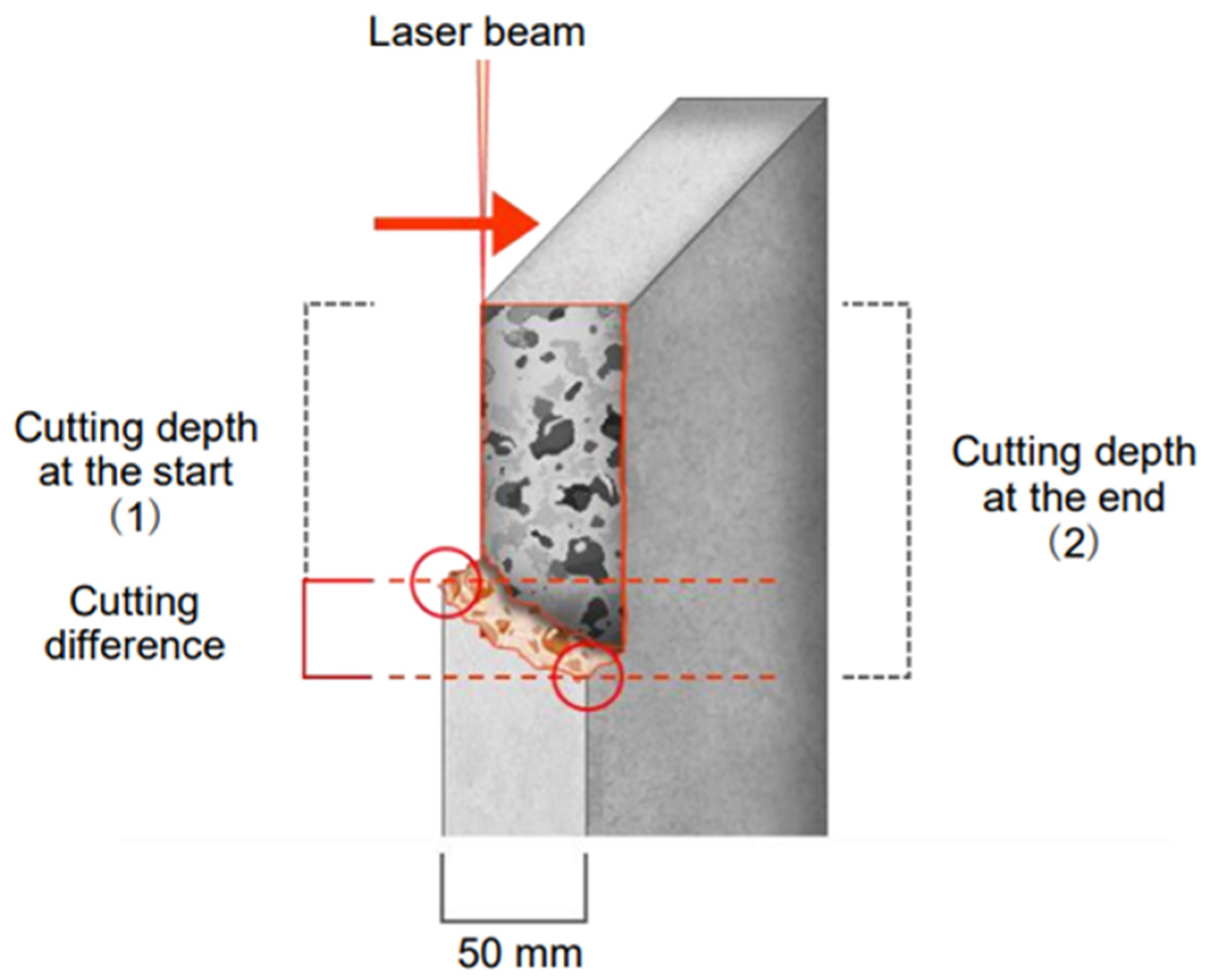
A digital calliper was used to measure the cutting depth at the end of a cutting point. Furthermore, because the cutting depth differed at the start and end of the cut area, this difference in cutting depth was also compared.
Figure 2 shows a schematic of the difference in cutting depth. As shown in Figure 1, cutting with a laser requires a straight line to move the laser beam. When moving the beam, the speed, power, and gas pressure of the assist gas are maintained at a set level. However, the measured cutting depths differed at the start (1) and end (2) of the laser cut area, with a smaller cutting depth at the start (we refer to this difference as the cutting difference), as shown in Figure 2. The cutting difference can be calculated as follows:
CD = d2 − d1
CD: Cutting difference
d1: Cutting depth at the start of cutting

2.4.2. Measuring the Presence of Vitrification, Cracking, etc.
Visual observation and a digital microscope (Keyence VHX-5000) were used to confirm the presence or absence of vitrification, cracking, etc. The vitrified portions were also observed over time.
3. Experimental Results and Discussion
3.1. Comparison of Laser Power
Figure 3 and Figure 4 show the relationship between cutting speed and depth (end of cutting) at different powers and concrete strengths, respectively.
When concrete strength was 20 N/mm2, and laser powers were 6 and 9 kW, the cutting depth increased as the cutting speed decreased or the power increased.
The laser was able to cut to a depth of 116 mm when the power and cutting speed were 6 kW and 40 mm/min, respectively. In addition, when the power and cutting speed were 9 kW and 40 mm/min, respectively, the laser was able to cut to a depth of approximately 150 mm. Therefore, the average cutting depth for the 9 kW laser power was 1.28 times that of the 6 kW laser power. The correlation coefficient between the cutting speed and cutting depth at a concrete strength of 20 N was greater than 0.9.
In the case of concrete with a strength of 130 N/mm2 and laser powers of 6 and 9 kW, the slower the cutting speed, the greater the cutting depth was. In the case of the 6 kW laser power, the correlation coefficient between the cutting speed and cutting depth was 0.7, which was lower than that of the 9 kW laser power. When the cutting speed was 100 mm/min, the cutting effectiveness values of different powers were identical. When the cutting speed was less than 100 mm/min, the cutting effectiveness differed for different power values, indicating that the heat accumulation changed with concrete strength. Therefore, cutting high-strength concrete requires a high-power laser.
Consequently, the greater the concrete strength, the higher its denser is, and the thermal conductivity it becomes [17]. Hence, even when the laser is irradiated at the same power and cutting speed, concrete with a strength of 130 N/mm2 is highly susceptible to heat during irradiation. However, owing to its denser nature, a larger amount of heat is required to melt concrete. Moreover, concrete with a strength of 20 N/mm2 has a greater porosity. Therefore, it requires less heat to melt. Consequently, the lower the concrete strength is, the greater the cutting depth is. The results of other studies are similar to this ordinary concrete result. As a result, it was found that the different concrete affects the cutting speed or cutting depth.
3.2. Comparison of Concrete Strength
Figure 5 and Figure 6 show the relationship between cutting depth (end of cutting) of a strength of 20 N/mm2 and cutting depth of a strength of 130 N/mm2 for the two laser powers.
When the laser power was 6 kW, the cutting depth remained almost the same for concretes with different strengths. In this experiment, the cutting depth ranged between 50 and 120 mm.
In the case of the 9 kW laser power, the cutting depth was between 75 and 200 mm, which was larger than that of the 6 kW laser power. Hence, the heat effect on the specimen was larger with the 9 kW laser power, and the cutting depth was approximately the same, regardless of the concrete strength.
This phenomenon caused the concrete with a strength of 130 N/mm2 to be completely cut, and in the case of the concrete with a strength of 20 N/mm2, the molten material re-adhered after cutting.
This result was due to the thermal effects of concrete strengths mentioned in Section 3.1. High-strength concrete has a high material separation resistance and a high viscosity [18]. In addition, owing to its higher density, the cutting was likely due to the heat explosion and similar effects.
3.3. Differences in Cutting Surfaces Due to Different Concrete Strengths
Figure 7 shows the surface of the cut part of the specimens for each concrete strength after laser cutting. In the photo, the cutting depths are approximately 118 mm and 126 mm for the specimens with strengths of 20 N/mm2 and 130 N/mm2, respectively.
While observing the cross-sections, the specimen with a strength of 20 N/mm2 showed dull vitrification. Contrastingly, the specimen with a strength of 130 N/mm2 showed glossy vitrification. This is because when the concrete strength is low, the impact of the laser is channelled in the depth direction, whereas when the concrete strength is high, heat tends to accumulate locally, owing to the higher thermal conductivity and density [19,20].
3.4. Difference in Cutting Depth
Figure 8 shows the cutting depth at the start and end points of the cutting distance. This graph indicates that the cutting depth at the cutting start and end points was the same until a cutting distance of approximately 20 mm was reached. At a cutting distance of 20–35 mm, the cutting difference increased. When the cutting distance was in the range of 35–50 mm, the cutting difference was almost the same. This phenomenon indicates that the effect of the concrete material on the concrete cutting differs depending on the cutting distance. This point has not been discussed before. It is important to understand this phenomenon in the case of cutting concrete over 80 mm using a high-power laser.
Figure 9 shows a schematic diagram of the cutting difference regarding the heat influence by laser cutting distance. This figure shows the surface condition of the cutting start point because of the difference in cutting distance. The upper part shows the concrete inside the model according to each cutting distance. The lower row shows the photograph of the cutting start point for each cutting distance. The 50 mm point shows the cutting start point (c.1) and cutting end point (c.2) only. This model describes the situation in Figure 8.
The reason for this is that the thermal effect of the laser during cutting melts the cement and aggregates materials contained in the concrete, which are ejected at the beginning of the laser cutting, as shown in Figure 9. As the laser moves across the concrete, the material melted by the heat at the cutting site accumulates and fills the area where the cutting begins, creating the difference in cutting. Hence, it was confirmed that when the cutting was deep and the cutting distance was long, glass and the like were accumulated inside the concrete. Thus, the glass must be removed.
Furthermore, as shown in Figure 10, the heat accumulation (the amount of heat received) differed at the start and end points of cutting. For example, at the laser power of 6 kW and cutting speed of 20 mm/min, the specimen received 6 kJ of heat immediately after irradiation and 900 kJ of heat at the end. The higher the amount of heat was, the higher the temperature of the specimen was, indicating why the specimen was relatively hot at the end of the cutting. As the amount of heat increased, the heat effects and the amount of glass increased, generating a greater cutting depth.
3.5. Cutting Effectiveness of the CO2 and Fibre Lasers
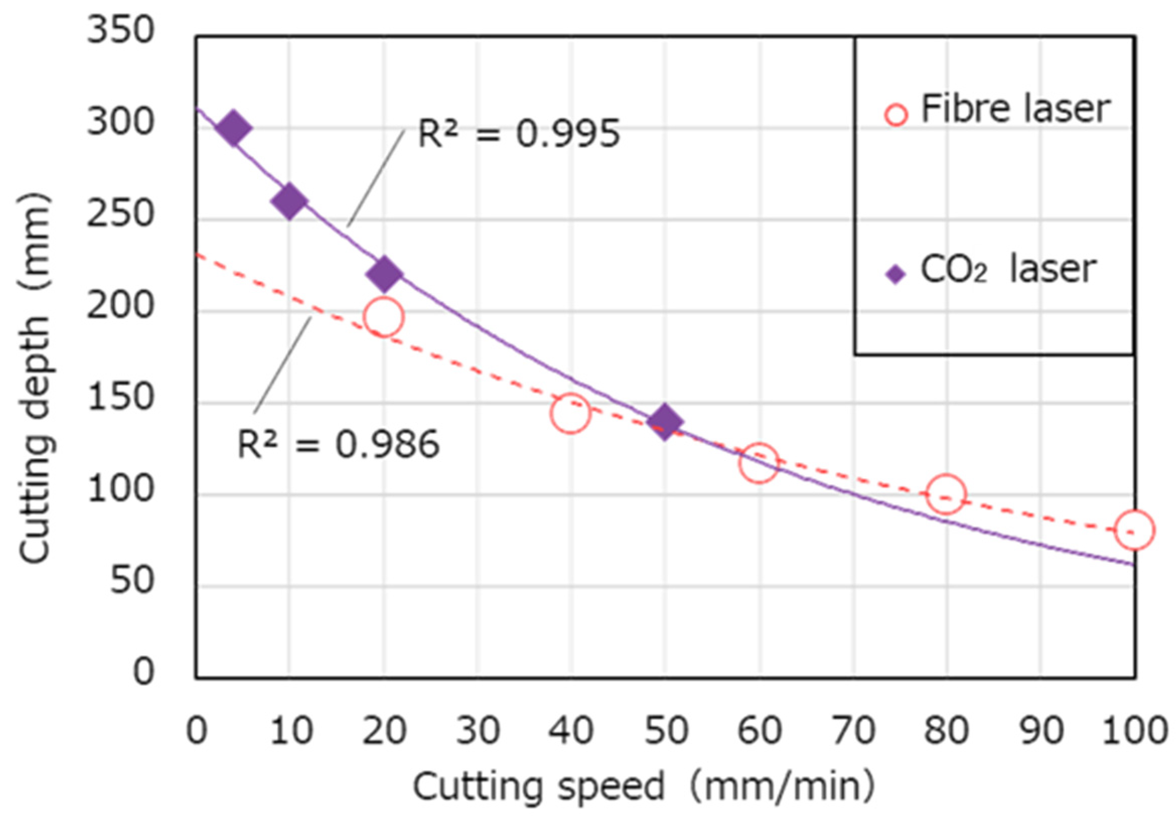
Figure 11 shows the cutting depths of the CO2 and fibre lasers when the laser power was 9 kW. The cutting depth of the CO2 laser was approximately 20 mm greater than that of the fibre laser at the cutting speed of 20 mm/min. This is due to differences in focal length, power density, assist gas flow rate, and similar parameters caused by differences in the laser oscillator and irradiation conditions. However, at the cutting speed of 50 mm/min, an identical cutting depth was obtained. Although CO2 laser data were not available, the results in the graph show that the cutting depths of the CO2 and fibre lasers were reversed or approximately the same at cutting speeds greater than 50 mm/min. Thus, both the CO2 and fibre lasers were roughly equivalent in terms of their cutting effectiveness in concretes at high speeds. However, the CO2 laser resulted in deeper cutting depths at slower speeds.
4. Conclusions
In this study, to compare two different concrete strengths for cutting to a depth of 200 mm thick concrete, the laser conditions were changed and the surface conditions of cutting were observed. This study confirmed that concrete cutting by a high-power fibre laser, which can be brought to construction sites, could be used where noise and dust are major problems. The main conclusions of this study are as follows:
- At concrete strengths of 20 N/mm2, the trend of cutting depth was the same even if the laser output was different.
- At concrete strengths of 130 N/mm2, the same cutting depth was indicated when the speed was 100 mm, even if the laser output was different. However, when the speed decreased, the difference in laser output greatly affected the difference in cutting depth.
- Cutting to a depth of 200 mm or more required a laser power of 9 kW and a cutting speed of 20 mm/min.
- Regardless of the concrete strength, the concrete melted and vitrified if the heat effect became large.
- In laser cutting, the cutting depths at the start and end points of cutting differed depending on the cutting method.
- The CO2 and fibre lasers were roughly equivalent in terms of their cutting effectiveness in different concretes. However, the same cutting depth was indicated when the speed was 50 mm. Furthermore, the CO2 laser resulted in deeper cutting depths at slow speeds than those of the fibre laser.
Author Contributions
All authors contributed equally to the various aspects of this study. Both authors have read and agreed to the published version of this manuscript.
Funding
This research received no external funding.
Acknowledgments
The authors gratefully acknowledge Kanamoto Corporation, ITO shokai, and some other laser companies for their helpful suggestions.
Conflicts of Interest
The authors declare no conflict of interest.
References
- Kasai, Y. New dismantling method. Concr. J. 1973, 11, 39–48. [Google Scholar]
- Kasai, Y. History of concrete technology 4th Transition of demolition method. Concr. J. 1992, 30, 87–91. [Google Scholar]
- Kawashima, T.; Takagi, M. Dismantling method using a diamond wire saw. Concr. J. 1991, 29, 35–39. [Google Scholar]
- Yanagida, K. Reinforced concrete (RC) building demolition method ③ Low noise demolition method. Concr. J. 2016, 54, 398–402. [Google Scholar]
- Yuasa, N. Reinforced concrete (RC) building demolition method ① History of reinforced concrete demolition method. Concr. J. 2016, 54, 189–194. [Google Scholar]
- Kitani, Y. High Power Laser Welding in Vacuum. J. JWS 2020, 89, 51–55. [Google Scholar] [CrossRef]
- The Laser Society of Japan. Chapter 47 on Laser Applications; The Optronics Co., Ltd.: Tokyo, Japan, 1998; pp. 117–132. [Google Scholar]
- Nagai, K.; Beckemper, S.; Poprawe, R. Laser Drilling of Holes in Different Kinds of Concrete. Civ. Eng. J. 2018, 4, 766–775. [Google Scholar] [CrossRef] [Green Version]
- Sugita, K.; Mori, M.; Fujioka, T. Application of CO, Laser to Concrete Cutting. Concr. J. 1986, 24, 13–22. [Google Scholar] [CrossRef] [Green Version]
- Yoshizawa, H.; Wignarajah, S.; Saito, H. Study on laser cutting of concrete. Trans. Japan Weld. Soc. 1989, 20, 31–36. [Google Scholar]
- Nguyen, P. Experimental characterization of concrete removal by high-power quasi-continuous-wave fiber laser irradiation. J. Laser Appl. 2017, 29, 041501. [Google Scholar]
- Lee, D.; Seo, Y.; Pyo, S. Effect of Laser Speed on Cutting Characteristics of Cement-Based Materials. Materials 2018, 11, 1055. [Google Scholar] [CrossRef] [PubMed] [Green Version]
- Kutsumizu, A.; Tomura, H.; Wakizaka, T.; Hishikawa, K.; Moriya, M. Experimental study on concrete cutting bu CO2 laser beam. J. Struct. Constr. Eng. AIJ 1994, 464, 43–52. [Google Scholar] [CrossRef] [Green Version]
- Nagai, K.; Sato, M.; Hattori, H.; Kinugasa, M. Rock excavation with laser. In High-Power Lasers in Civil Engineering and Architecture; SPIE-The International Society for Optical Engineering: Osaka, Japan, 2000; Volume 3887, pp. 277–286. [Google Scholar]
- Wignarajah, S.; Nagai, K. Between a rock and a hard place. Ind. Laser Solut. Mag. 2005, 20, 8–12. [Google Scholar]
- Nagai, K. Laser processing for construction site. Laser Inst. 2010, 39, 744–748. [Google Scholar]
- Seo, T.Y.; Lee, D.; Pyo, S. High-Power Fiber Laser Cutting for 50-mm-Thick Cement-Based Materials. Materials 2020, 13, 1113. [Google Scholar] [CrossRef] [PubMed] [Green Version]
- Saito, H. Optical Measurements in Experimental Mechanics; The Optical Society of Japan: Japan, 1965; pp. 3–10. [Google Scholar]
- Li, Z.; Li, Q. Relationship between Compressive Strength and Thermal Conductivity of Concrete; Japan Concrete Institute: Tokyo, Japan, 2014; Volume 36, pp. 2050–2055. [Google Scholar]
- Research Institute on Building Cost. Survey Report of “High-Strength Concrete”; New Technology Survey Report in Japan; Research Institute on Building Cost: Japan, 2010; pp. 80–85. [Google Scholar]
Figure 1.
Schematic of laser irradiation.
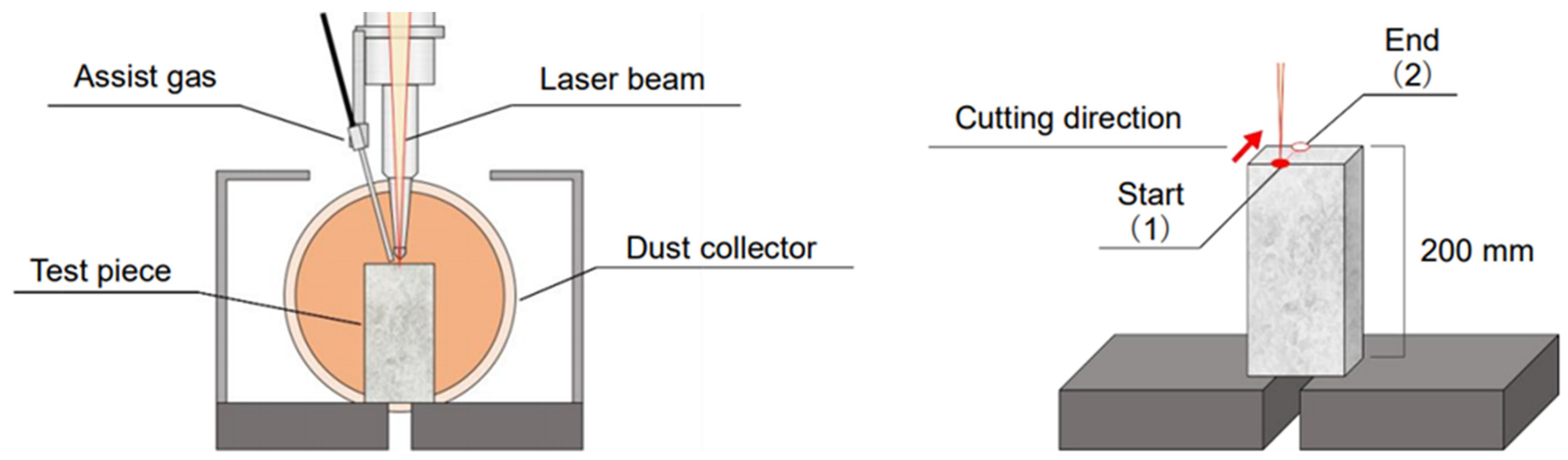
Figure 3.
Relationship between the cutting speed and cutting depth for the two laser powers (compressive strength 20 N/mm2).
Figure 3.
Relationship between the cutting speed and cutting depth for the two laser powers (compressive strength 20 N/mm2).
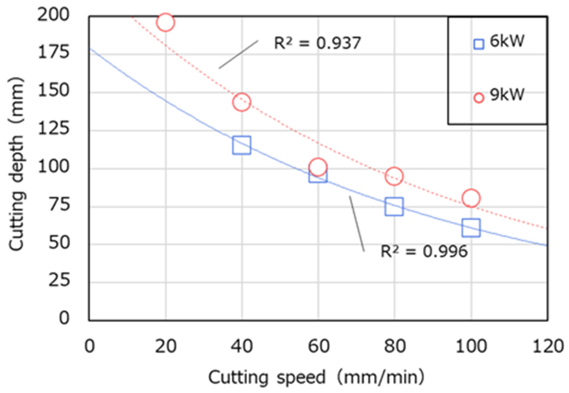
Figure 4.
Relationship between the cutting speed and cutting depth for the two laser powers (compressive strength 130 N/mm2).
Figure 4.
Relationship between the cutting speed and cutting depth for the two laser powers (compressive strength 130 N/mm2).

Figure 5.
Correlation between cutting depth and concrete strength (laser 6 kW).
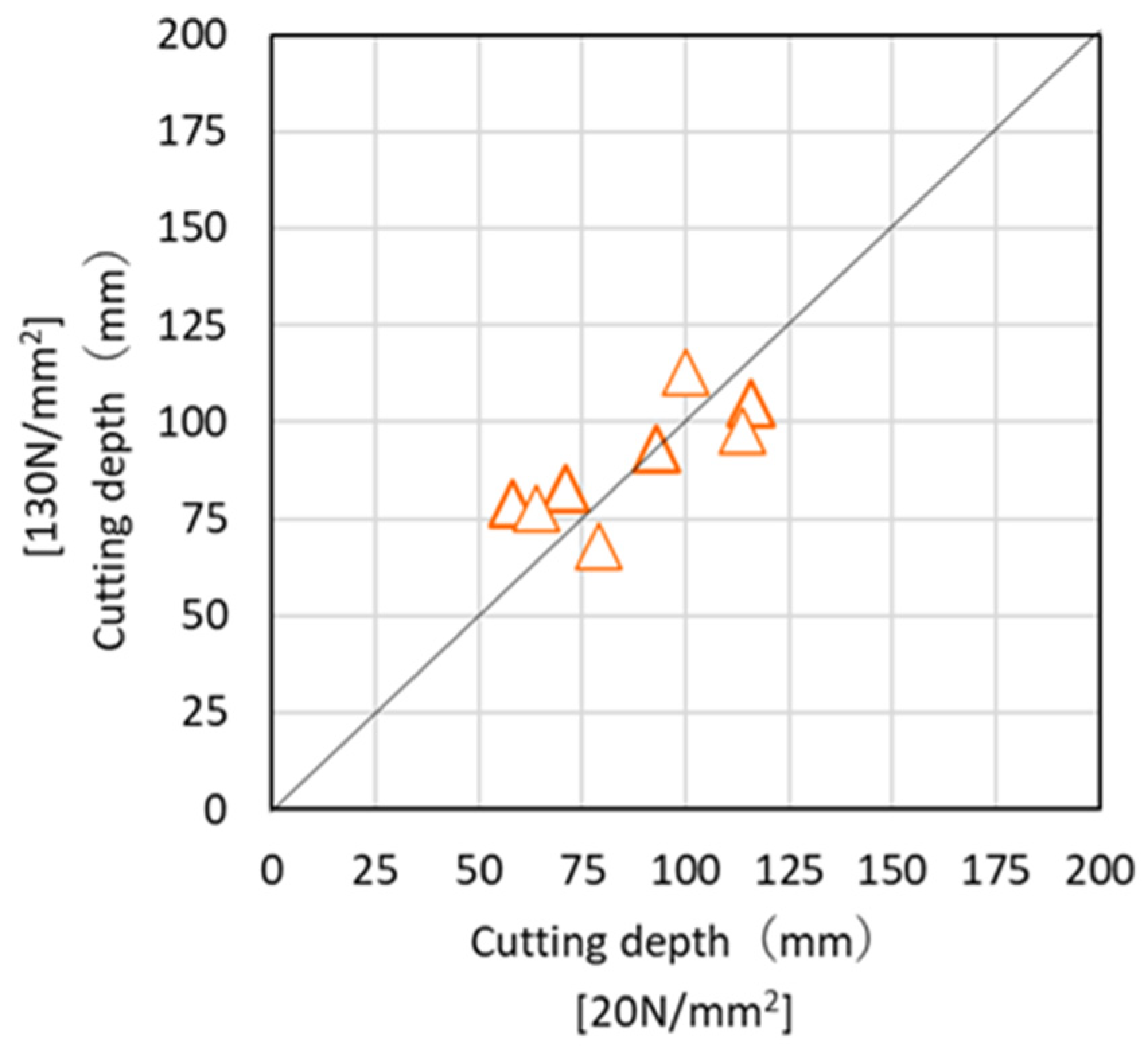
Figure 6.
Correlation between cutting depth and concrete strength (laser 9 kW).
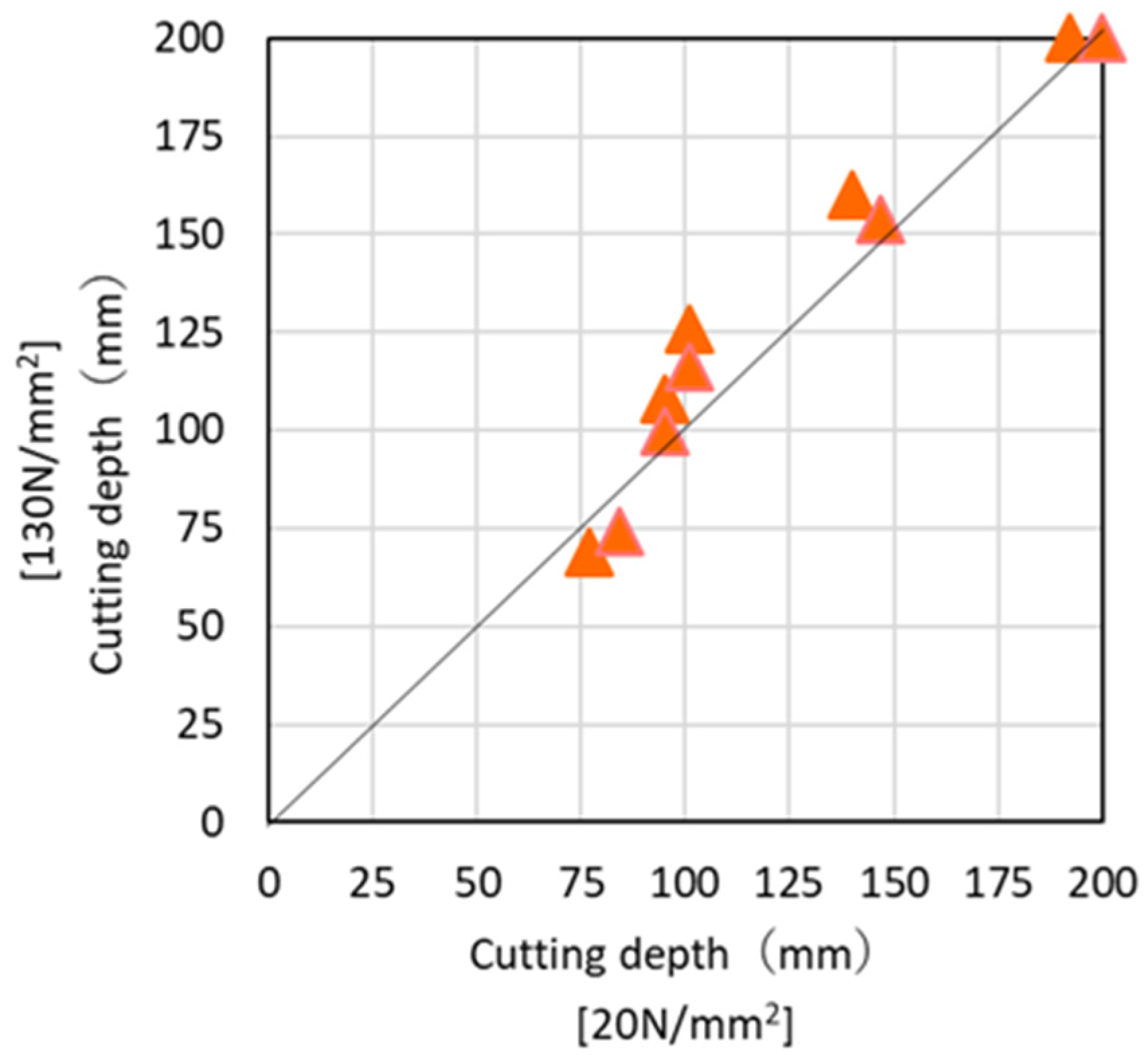
Figure 7.
Cut surface after irradiation.
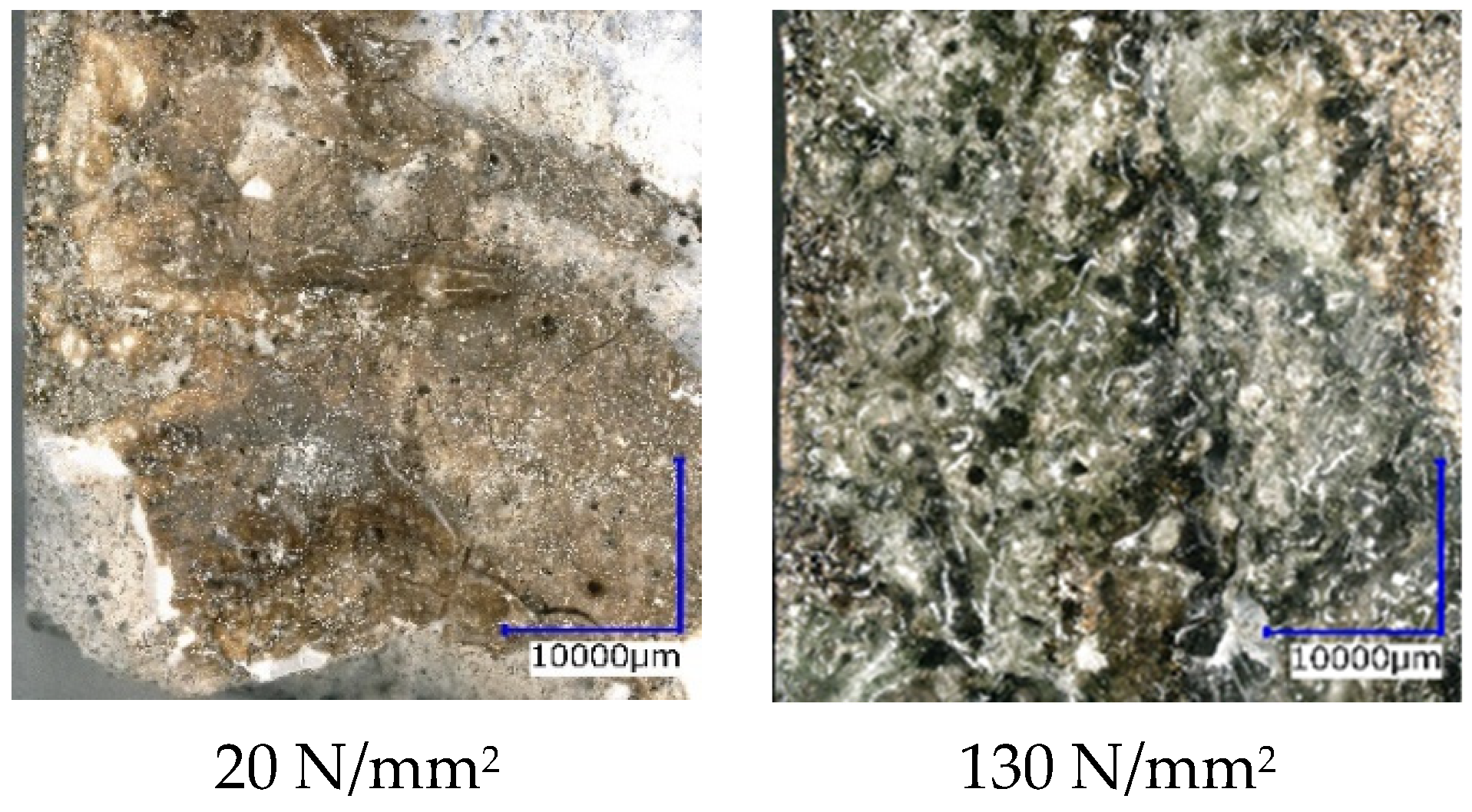
Figure 8.
Result in the cutting difference due to difference in the cutting distance (laser: 9 kW; speed: 60 mm/min; strength: 20 N/mm2).
Figure 8.
Result in the cutting difference due to difference in the cutting distance (laser: 9 kW; speed: 60 mm/min; strength: 20 N/mm2).
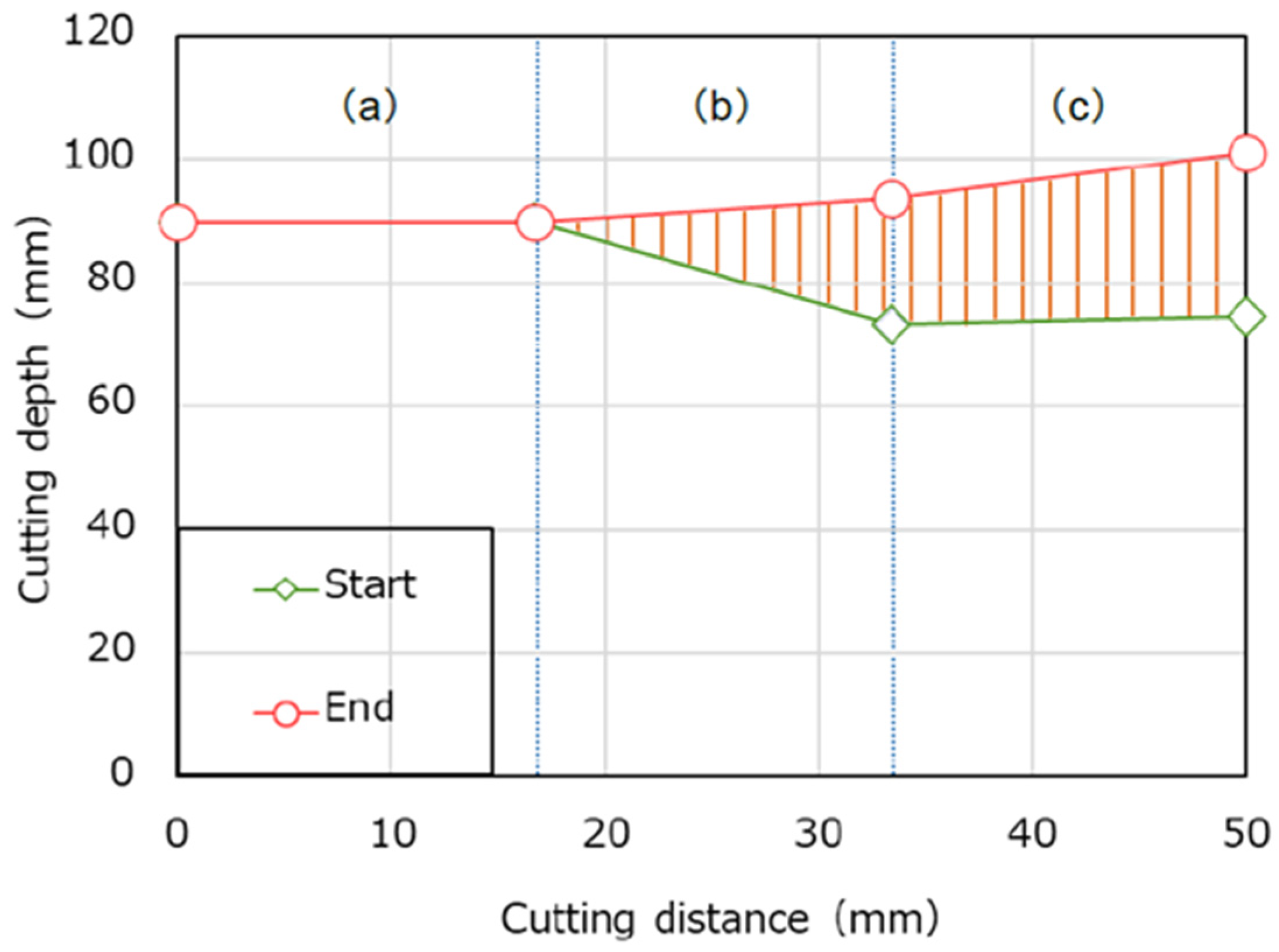
Figure 9.
Schematic of the cutting difference owing to heat influence (laser: 9 kW; speed: 60 mm/min; strength: 20 N/mm2).
Figure 9.
Schematic of the cutting difference owing to heat influence (laser: 9 kW; speed: 60 mm/min; strength: 20 N/mm2).

Figure 10.
Schematic of thermal influence due to irradiation position.
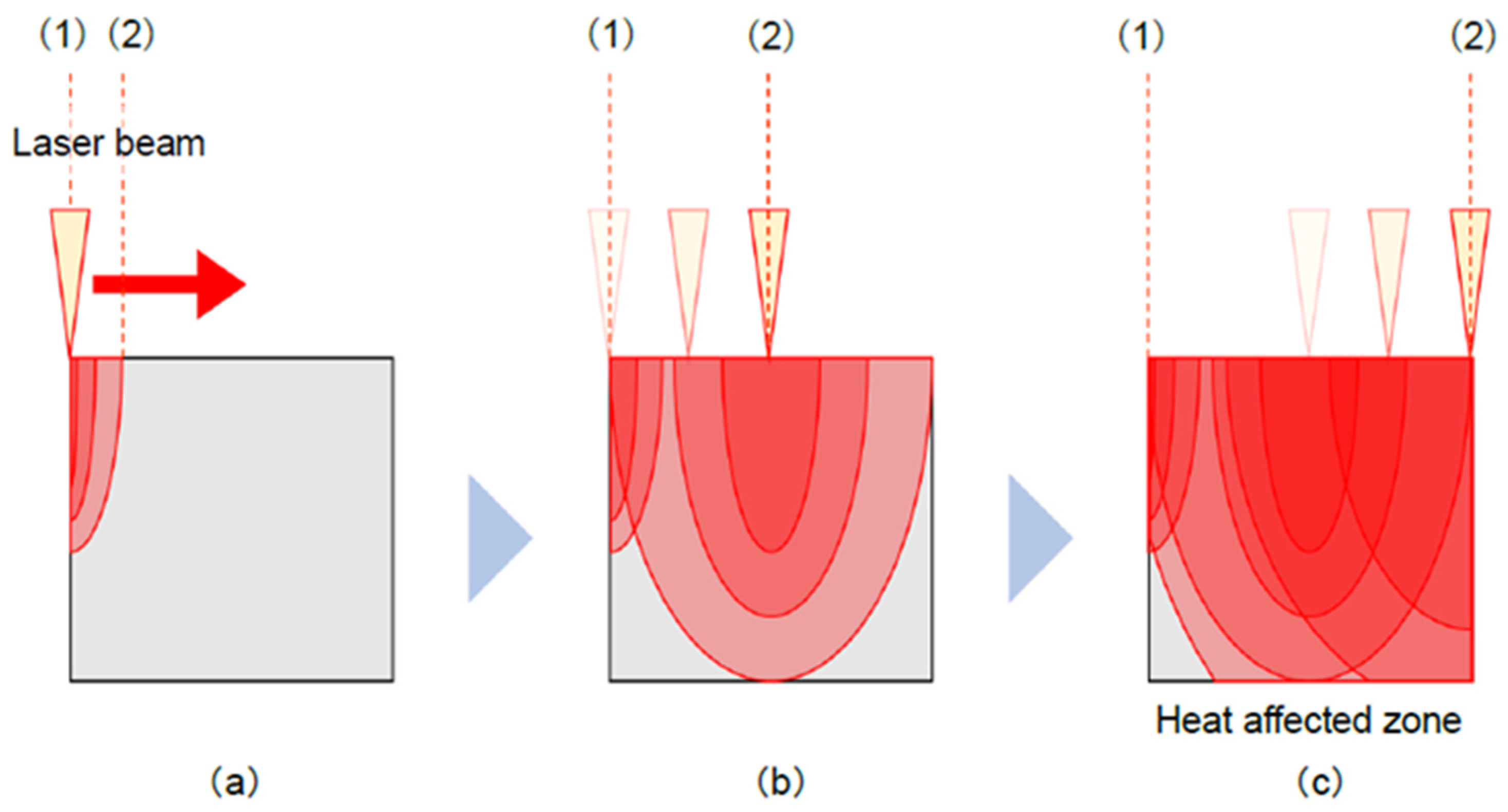
Figure 11.
Cutting depth curves of the CO2 and fibre lasers (laser 9 kW).

Table 1.
Mix proportion.
| Concrete | Ordinary | High-Strength |
|---|---|---|
| Strength (N/mm2) | 20 | 130 |
| Slump (cm) | 18 | 65 |
| Air content (%) | 4.5 | 2.0 |
| Water-cement ratio (%) | 63.3 | 14.0 |
| Sand-aggregate ratio (%) | 50.7 | 31.0 |
Table 2.
Laser irradiation conditions.
| Laser output (kW) | 6, 9 |
| Fibre core diameter (μm) | 100 |
| Cutting speed (mm/min) | 20, 40, 60, 80, 100 |
| Gas type | Air |
| Gas pressure (MPa) | 0.95 |
| DFS distance (mm) | 0 |
Publisher’s Note: MDPI stays neutral with regard to jurisdictional claims in published maps and institutional affiliations. |
© 2021 by the authors. Licensee MDPI, Basel, Switzerland. This article is an open access article distributed under the terms and conditions of the Creative Commons Attribution (CC BY) license (https://creativecommons.org/licenses/by/4.0/).
Share and Cite
MDPI and ACS Style
Nagai, K.; Shimizu, K. Using a High-Power Fibre Laser to Cut Concrete. Appl. Sci. 2021, 11, 4414. https://doi.org/10.3390/app11104414
AMA Style
Nagai K, Shimizu K. Using a High-Power Fibre Laser to Cut Concrete. Applied Sciences. 2021; 11(10):4414. https://doi.org/10.3390/app11104414
Chicago/Turabian StyleNagai, Kaori, and Kazuki Shimizu. 2021. "Using a High-Power Fibre Laser to Cut Concrete" Applied Sciences 11, no. 10: 4414. https://doi.org/10.3390/app11104414
Note that from the first issue of 2016, this journal uses article numbers instead of page numbers. See further details here.