Case Report

Assessment of the Impact of Electric Vehicle Batteries in the Non-Linear Control of DC Microgrids

by
Pierre Samuel
1,
Rachid Eddaaif
1,
Andrés González-Zumba
2 and
Jean-Michel Clairand
3,*
1
Ecole Nationale Supérieure de l’Electronique et Ses Applications, 95000 Cergy, France
2
Departamento de Matemática Aplicada, Universitat Politècnica de València, Camino de Vera s/n, 46022 Valencia, Spain
3
Facultad de Ingeniería y Ciencias Aplicadas, Universidad de las Américas-Ecuador, Quito 170122, Ecuador
*
Author to whom correspondence should be addressed.
Appl. Sci. 2021, 11(10), 4415; https://doi.org/10.3390/app11104415
Submission received: 11 April 2021 / Revised: 3 May 2021 / Accepted: 10 May 2021 / Published: 13 May 2021
(This article belongs to the Section Environmental Sciences)

Abstract

:
Several efforts need to be performed in transportation and energy production to mitigate the current environmental issues that are related to fossil fuel use. The implementation of DC microgrids and the use of electric vehicles seem to be an adequate solution. However, various technical challenges have to be addressed, like grid stability issues. Thus, this case report assesses the impact of an electric vehicle load in a DC microgrid, subject to nonlinear control theory. The EV battery pack is modeled and simulated. Subsequently, it is included as a load in an available model of nonlinear control of DC microgrids. The results demonstrate high stability with this new load and the feasibility of its implementation.

1. Introduction

Microgrids received beneficial interest a few years ago. They have significant benefits for the electrical grid and the energy users by using distributed generation (DG) and energy storage systems (ESSs). The benefits include enhancing electricity quality, decreasing pollution, congestion, reducing supply problems, and increasing the energy efficiency [1].
A microgrid could be described as a cluster of loads, DGs, and ESSs operated in conjunction to provide electricity securely and linked to the host power system at the distribution level at the Point of Common Coupling (PCC) [2]. Besides, microgrids can work independently, or they can be connected to a grid based on the voltage type: AC, DC, or hybrid [3].
Generally, microgrids incorporate DG units and energy storage technologies that are focused on renewable energy (RE). Some examples of DG units include PV panels, wind turbines, diesel generators, and microturbines. Some ESS examples include electric batteries, supercapacitors, thermal storage, and flywheels. These are the primary microgrid components, and the main answer for rural areas without primary grid connectivity is considered [4].
AC microgrids have been widely studied in the literature; however, growing attention has recently been devoted to DC microgrids due to their higher reliability, improved performance for various kinds of RE sources and ESS, as well as improved compliance with, among others, DC consumer electronics [5]. Furthermore, as components are linked along a DC bus, no issues exist with reactive power, energy efficiency, and frequency regulation, which leads to a notably less complicated control system [6]. However, various disadvantages must be overcome during the implementation of DC microgrids, like the commitment to construct DC distribution lines, and the safety of DC grids is more complicated [7].
Big cities suffer environmental issues due to internal combustion vehicles. Thus, it is expected that the purchasing of electric vehicles (EVs) would increase to mitigate these environmental issues. Some papers have proposed the control, operation, and planning of DC microgrids with the incorporation of EVs [8,9,10]. Moreover, EVs own a key component, which is an electric battery that has recently received considerable attention since it is an energy storage system.
Because many utilities and scientists use software simulation packages to model and analyze different problems in microgrid systems, grid components must be modeled in a sufficient way to accurately represent device behavior and performance. However, battery energy storage systems in microgrids have been less studied in the literature, since they are relatively new components [11]. Li-ion batteries are the most mature and commercial technologies used in power systems, such as DC microgrids. However, the integration of Li-ion batteries, like EV batteries, require formal modeling [12].
Different models of batteries have been carried out for a long time [13,14,15]. Nowadays, EVs typically own a Li-Ion battery. Some researchers have proposed different modeling for Li-Ion batteries. Some studies consider thermal modeling. For example, in [16], a generic electrothermal model for Li-ion battery is presented. The authors of [17] present the simulation a Li-ion battery pack for a lightweight commercial EV. In [18], an equivalent circuit model, which keeps a straight correlation between its parameters and the battery electrochemical principles, is presented.
Some other works have focused on the optimal performance of batteries. For example, in [19], an optimal charging pattern for the high-performance multistage constant current charge method is studied. The authors of [20] presented a nondissipative equalization scheme that is based on fuzzy logic control to improve the inconsistency of series-connected Lithium-ion batteries.
Other authors studied models of battery parameters. For example, in [21], the impedance spectra were modeled based on an equivalent circuit model for Li-Ion Batteries. The authors of [22] proposed the co-estimation of state-of-charge ( S O C ) and state-of-health for Li-Ion batteries considering fractional-order calculus. In [23], a model for predicting the battery’s remaining useful life was presented using the Particle Filtering framework. The authors of [24] studied a non-linear fractional-order estimator for S O C indication, providing a guarantee for stability and robustness of the error system under certain assumptions.
Few works have proposed the operation of DC microgrids considering the introduction of EVs. In previous work, [25], the non-linear control of a DC microgrid considering EV charging was proposed. However, the presented model of the battery EV was simple. Thus, the aim of this paper is to assess the impact of accurate modeling of the EV’s battery in a non-linear control model of a DC microgrid.

2. Background: Non-Linear Control of DC Microgrid

This section presents the background information for the non-linear control of dc-microgrid with available mathematical tools and an assumed microgrid configuration.

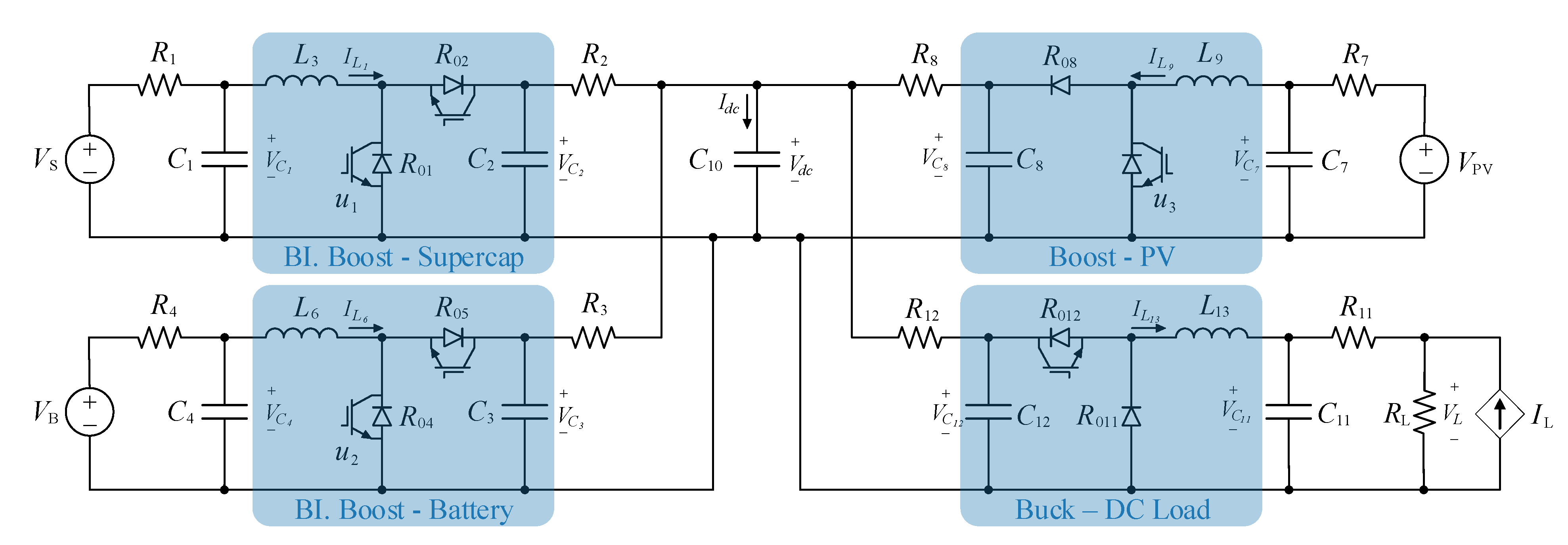
2.1. Assumed Microgrid Configuration

For this study, the proposed microgrid includes DG: photo-voltaic (PV) panel; and ESSs: a battery, and a supercapacitor; and DC/DC converters, as can be seen in Figure 1. Moreover, the microgrid circuit configuration is illustrated in Figure 2. The supercapacitor and electric battery work as storage for the generation from the PV that is not consumed, but they also allow for mitigating disturbances due to transients. The electric battery could provide a low-frequency current and the supercapacitor, a high-frequency one. A boost converter was selected for the DC/DC converter, which is composed of three phases and it includes six switches connected in parallel. The switches could be independently controlled by three different duty cycles.
Later in this study, the simulation of the charging of an EV battery will be simulated as a new load for the DC microgrid. Note that, bidirectional flow, i.e., Vehicle-to-grid (V2G), is not considered.
With this configuration, various power electronics equations could be obtained, described as follows:
d V C 1 d t = V P V R 1 C 1 V C 1 R 1 C 1 I L 1 C 1 ,
d V C 2 d t = V B A T R 2 C 2 V C 2 R 2 C 2 I L 2 C 2 ,
d V C 3 d t = V S C R 3 C 3 V C 3 R 3 C 3 I L 3 C 3 ,
d I L 1 d t = V C 1 L 1 [ ( R 01 R 02 ) u 1 + R 02 ] I L 1 L 1 ( 1 u 1 ) V D C L 1 ,
d I L 2 d t = V C 2 L 2 [ ( R 03 R 04 ) u 2 + R 04 ] I L 2 L 2 ( 1 u 2 ) V D C L 2 ,
d I L 3 d t = V C 3 L 3 [ ( R 05 R 06 ) u 1 + R 06 ] I L 3 L 3 ( 1 u 3 ) V D C L 3 ,
d V D C d t = 1 C D C [ ( 1 u 1 ) I L 1 + I L 2 + I L 3 I L O A D ] ,
I L O A D = I L 4 + I L 5 + I L 6 ,
where V C 1 , V C 2 , and V C 3 are the voltages of capacitors C 1 , C 2 , and C 3 . V P V , V B A T , V S C , V D C are, respectively, the voltages of PV panel, battery, supercapacitor, and DC microgrid. I L 1 , I L 2 , I L 3 , I L 4 , I L 5 , and I L 6 are the inductances L 1 , L 2 , L 3 , L 4 , L 5 , and L 6 currents. R 01 , R 02 , R 03 , R 04 , R 05 , and R 06 are the internal resistances of the converter’s switches. u 1 , u 2 , and u 3 are the duty cycles of the converters. I L O A D is the total load current.

2.2. Non-Linear Control

DC microgrids could experience stability problems, since the PV generation and the electrical load presents significant uncertainties and fluctuations, as previously explained. Hence, to ensure stability, the voltage needs to remain at adequate levels. In this work, a non-linear control is considered for the considered DC microgrid. Figure 2 depicts the assumed configuration scheme for the non-linear control.
Although the linear PI control technique is the most common strategy for power-converters and microgrids implementations, since a PI control is designed for working around a linearized operation point, this is generally not able to cope with the system’s non-linearities and disturbances. Specifically, in microgrid applications, the PI strategy presents a scarce dynamic response (such as bigger overshoots in transients and a slower speed response) as compared to the better performance and greater energy efficiency given by the nonlinear choice, see [26,27,28]. In addition, implementing a non-linear control does not require high computing resources [29].

2.3. Control of V D C

The error between V D C and V D C * is calculated following the equation:
e V D C = ( V D C V D C * )
This is a reference value, which allows for controlling the voltage V D C .
The integrator of the error is calculated, as follows:
α ˙ 7 = K 7 α e V D C
e ˙ V D C = K 7 e V D C K ¯ 7 α 7
From (7) and (11), it can be written:
( I L 2 + I L 3 ) * = V D C R L O A D ( 1 u 1 ) I L 1 K ¯ 7 C C α 7 K 7 C D C ( V D C V D C * )
with K 7 , K 7 ¯ , and K 7 α , positive gains, which are handled by imposing desired dynamics to the closed loop system. Then:
α 7 ˙ e V D C ˙ = 0 K 7 α K 7 ¯ K 7 α 7 e V D C
Thus, the eigenvalues are:
λ 7.1 = 0.5 ( K 7 + K 7 2 4 K 7 ¯ K 7 α )
λ 7.2 = 0.5 ( K 7 K 7 2 4 K 7 ¯ K 7 α )
The transfer function H 7 can be expressed, as follows, based on these eigenvalues:
H 7 = 1 s 2 + K 7 s + K 7 α K 7 ¯ = G s 2 ω 7 + 2 ζ ω 7 s + 1
with G the transfer function gain, ω 7 the eigen-pulsation, and ζ a constant that helps to tune the dynamic. Hence:
ω 7 = K 7 ¯ K 7 α ζ = K 7 2 K 7 ¯ K 7 α
For the dynamic, it was chosen ω 7 = 2 π 0.1 = 62.8 r a d . s 1 , ζ = 2 2 and K 7 α = 1 .

2.4. Current Control

One can know the required current in the system through the formulation of the previous subsection. The expression ( I L 2 + I L 3 ) * has been separated in low and high-frequency terms, respectively. This current decomposition is performed through a low-frequency filter, which was included in the model.

2.4.1. Control of I L 2

The same non-linear control was used to control I L 2 .
e I L 2 = ( I L 2 I L 2 * )
α ˙ 4 = K 4 α e I L 2
e ˙ I L 2 = K 4 e I L 2 K ¯ 4 α 7
With the Equations (5) and (19), we can obtain:
u 2 = 1 ( V D C + ( R 04 R 03 ) I L 2 [ V D C V C 2 + R 04 I L 2 L 2 ( K 4 e I L 2 + K ¯ 4 α 4 I L 2 * ˙ ) ]
To tune the constant K 4 , K 4 ¯ , and K 4 α , the same method above was used. Hence, K 4 = 8796.2 , K 4 ¯ = 6283 2 , and K 4 α = 1 .

2.4.2. Control of I L 3

Using the same method, the voltage u 3 is defined:
u 3 = 1 ( V D C + ( R 06 R 05 ) I L 2 [ V D C V C 3 + R 06 I L 3 L 3 ( K 6 e I L 3 + K ¯ 6 α 6 I L 3 * ˙ ) ]
The following values for the constants were assumed:
K 6 = 1 ω 6 = 2 π . 10 000 ζ 6 = 2 2

2.5. Control of V P V and I L 1

Finally, the voltage of the PV panel has to be controlled. The control is defined, as per [29,30]:
e V C 1 = ( V C 1 V C 1 * )
e I L 1 = ( I L 1 I L 1 * )
α ˙ 1 = K 1 * e V C 1
α ˙ 2 = K 2 * e I L 1
e ˙ V C 1 = K 1 e V C 1 K ¯ 1 α 1
e ˙ I L 1 = K 2 e I L 1 K ¯ 2 α 2
with K 1 , K 1 ¯ , and K 1 α constants that allow changing the dynamic of the PV panel control. Based on Equations (1) and (22):
I L 1 * = V P V V C 1 R 1 + C 1 K 1 ( V C 1 V C 1 * ) + C 1 K ¯ 1 α 1
Additionally, with (4) and (23), it obtains:
u 1 = 1 V D C + ( R 02 R 01 ) I L 1 [ V D C V C 1 + R 02 I L 1 L 1 ( K 2 ( I L 1 I L 1 * ) + K ¯ 2 α 2 C 1 K ¯ 1 K 1 * e V C 1 + ( C 1 K 1 1 R 1 ) ( K 1 e V C 1 + K ¯ 1 α 1 ) ) ]

3. Methodology

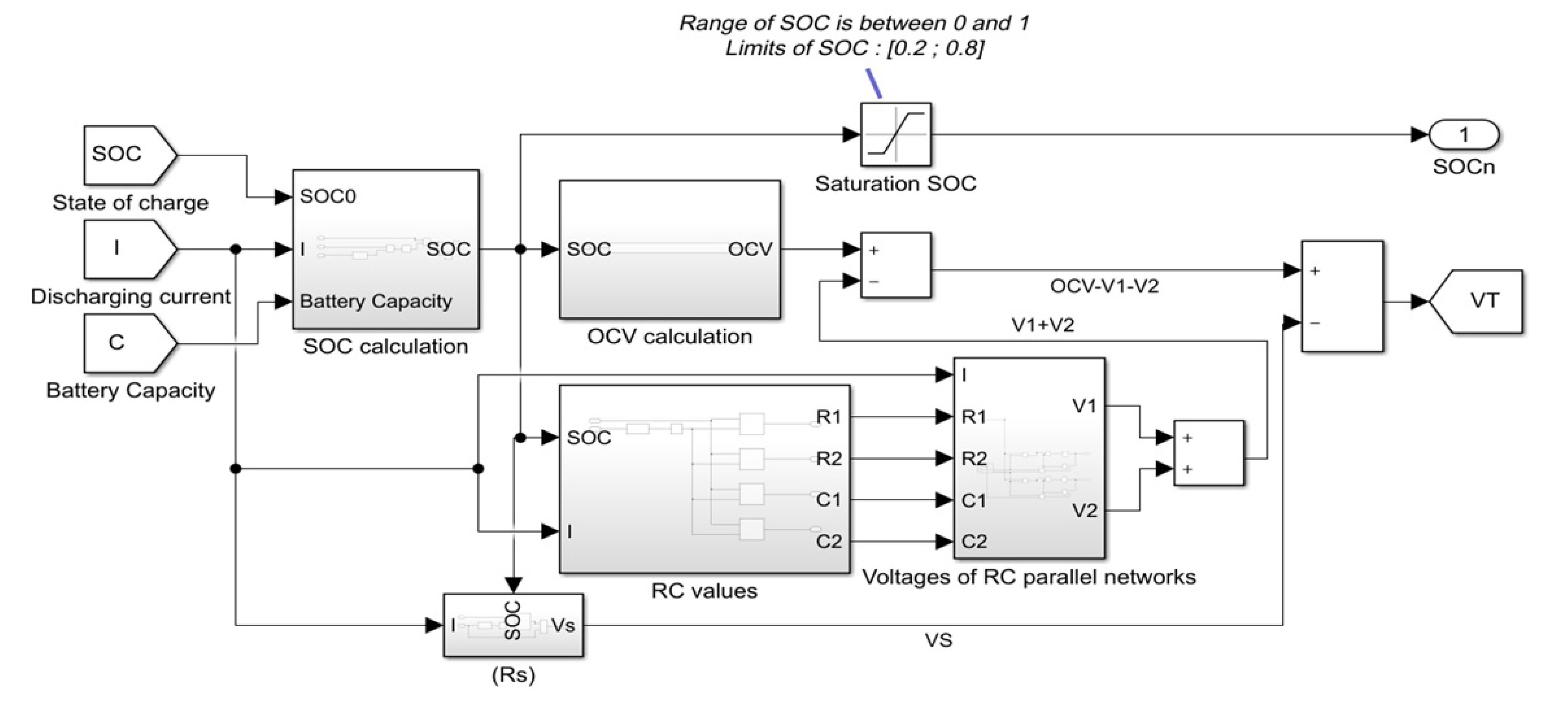
3.1. Modeling of a Battery Cell

The objective is to simulate the EV load by including a battery model in the DC microgrid. Afterwards, the impact of this new load in the DC microgrid will be assessed. A battery pack of an EV is a set of typical lithium-ion cells. The cells have to be connected in series and in parallel to generate the power that is required to run the EV. Various strategies for constructing battery packs exist: one consists of using big cells instead of many little cells, like for the Nissan Leaf [31].
The equivalent electric circuit model is used to present a modified feature in this paper, as per [32,33]. Figure 3 represents a Simulink model with three inputs (the discharging current, the initial S O C that ranges from 0% to 100%, and the battery capacity), which depend on the battery model. This model has five subsystems: the S O C calculation, the Open circuit voltage ( O C V ) calculation, the RC values, the RC network’s voltage, and the internal impedance.

3.1.1. Open Circuit Voltage Calculation

Open circuit voltage ( O C V ) corresponds to the battery voltage during a stable state when there is no perturbation. This is one of the critical parameters to be modeled. Because the O C V value depends on the S O C , a mathematical equation can express the link between them. The block diagram that is shown in Figure 4, based on [33], models this relationship and the following equation shows the mathematical relationship:
O C V = a × e b × S O C + c × S O C d × S O C 2 + e × S O C 3
where a = 1.031, b = 3.685, c = 0.2156, d = 0.1178, and e = 0.3201.

3.1.2. S O C  Calculation

This model uses three initial parameters to calculate the real-time S O C : the initial S O C noted as S O C 0 , the discharging current I, and the usable capacity C. Based on [33], the S O C could be calculated, as per:
S O C = S O C 0 0 t I C × 3600 d t

3.1.3. RC Values

The RC values represent the transient response of a lithium-ion battery cell voltage. The value of RC parallel networks ( R 1 , C 1 , R 2 , C 2 ) depends on S O C and current. To determine the most suitable RC values, an interpolation–extrapolation lookup method is used. According to [33], the series resistor for the developed model is equal to 0.001 Ω when the SOC is between 20–100% S O C , and 0.03 Ω is below 20%, regardless of the discharging current value. In order to have more precise resistors values, the graphs’ values on the experience of [34] are taken here.

3.1.4. Voltage of RC Parallel Network

Now, to calculate the RC parallel networks voltages, which correspond to the battery’s transient response, it can be expressed based on the parallel network formula, as follows:
I = V R + s × C × V
I s × C = V s × R × C + V
1 s × ( I C V R × C ) = V
Based on the equation above, this part’s simulation blocks can be constructed using Simulink’s tools to transcribe the equation. V 1 and V 2 are, respectively, the voltage for the first and second RC parallel network of the cell.

3.1.5. Voltage of the Series Resistors

Based on the following equation, the voltage of the series resistor can be calculated. V R s represents the voltage drop from DC internal resistance R s :
V R s = I × R s
The value of the R s is not fixed, but dependant on the current I and the S O C . Again, the lookup method interpolation–extrapolation is used here to determine the needed value of R s and, therefore, a 2-D lookup table is used to represent these values.

3.1.6. The Cell Output Voltage

To calculate the terminal voltage of the cell, the Kirchhoff’s voltage law based can be used to determine V t :
V t = O C V V 1 V 2 V s

3.2. Modeling of a Battery Pack

The following section is based on [35], which shows a battery pack model for 350 volts. A battery is composed of cells in series and parallel, as mentioned in [35]. The battery module model has to be connected in series. In this case, the single cell is considered and included as the terminal voltage to obtain the battery output. The terminal voltage of the battery is just the result of each submodel’s connections. This model allows us to have a more reliable battery, because each of the cells will impact the battery output voltage, closer to reality.

3.3. Charging the Battery Pack on a DC Microgrid

The integration of the previously modelized battery on a microgrid is now explained. It is based on [25], where the authors developed a functional model of a microgrid in Simulink. They developed a “Non-linear DC microgrid” that remains as stable as possible (less than 5% variations), so that there is no disturbance during the charge of the EV. This model has some advantages when compared to the AC microgrid.

3.3.1. The Microgrid Model

The model is composed of photovoltaic panels, a battery, and a supercapacitor for the supply part. To compensate for the fast variations, the use of a supercapacitor is preferred here and, for slow variations, the use of a battery is preferred here. There are three DC-DC boost converters. The purpose of this grid is to be stable and have VDC (output voltage of DC-MG) variations of less than 5% to avoid disruptions on the network. From the electrical diagram, they retrieved each element’s equations (voltage, current, etc.). Thus, they were able to transcribe these equations on Simulink to have their microgrid. In this case study, the studied EV battery is included as a new load to assess its impact on the stability of the DC microgrid.

3.3.2. The Battery Pack Connection

This part will focus on the battery model’s connection (see Section 3.1) to the microgrid that was studied previously (see Section 2.1). Thus, the new model will be more realistic than the microgrid model created by [25]. The other interest is to observe the impact of a battery on the power grid of the MG-DC, so we will have results that are closer to reality.
V D C t = 1 C D C [ ( 1 u 1 ) × I L 1 + I s t o r a g e I L O A D ]
In the model of [25], the output of V D C was created based on the previous equation, which depends on several parameters, including a current named I L o a d . Instead of having a fixed I L o a d , we will have a variable I L o a d . For this, the new I L o a d will now be the current coming out of the battery. We will obtain a current value by simply dividing the battery’s output voltage by a value equivalent to the battery’s internal resistance.
I L O A D = V T R v a l u e s
Note that the use of the lookup table method was required here to obtain the resistance values. In this way, the value of the internal resistance ( R v a l u e s ) will vary, depending on the battery voltage. This way, the microgrid can be “connected” through this manipulation, and the impact of the return current of the EV battery can be seen.

3.4. EV Charging Control

The EVs are assumed to charge at their maximum power. The modeling of the control of the charge of the EVs is expressed:
e I L i = ( I L i I L i * )
α ˙ c h a r g e i = K c h a r g e i α e I L i
e ˙ I L i = K c h a r g e i e I L i K ¯ c h a r g e i α c h a r g e i
with K c h a r g e i , K ¯ c h a r g e i , and K c h a r g e i α dynamic constants. The current I L i * is assumed to be at its maximum value. Equation (32) was used to calculate the duty cycle and topology of the EV circuit.
u 4 = 1 ( V C 4 + ( R 08 R 07 ) I L 4 [ V C 4 V D C + R 08 I L 4 L 4 ( K c h a r g e 1 e I L 4 + K ¯ c h a r g e 1 α c h a r g e 1 I L 4 * ˙ ) ]
u 5 = 1 ( V C 5 + ( R 010 R 09 ) I L 5 [ V C 5 V D C + R 09 I L 5 L 5 ( K c h a r g e 2 e I L 5 + K ¯ c h a r g e 2 α c h a r g e 2 I L 5 * ˙ ) ]
u 6 = 1 ( V C 6 + ( R 012 R 011 ) I L 6 [ V C 6 V D C + R 012 I L 6 L 6 ( K c h a r g e 3 e I L 6 + K ¯ c h a r g e 3 α c h a r g e 3 I L 6 * ˙ ) ]
where u 4 , u 5 , u 6 are the duty cycle of the converter of the EV.

4. Results and Discussion

Various simulations have been performed to assess the effectiveness of the proposed solution. The software Simulink from Mathworks and also Simscape electrical, which contain component libraries for modeling and simulating electronic, mechatronics, and electrical systems, were used for the simulation. As previously mentioned, a reliable cell is needed for a reliable battery, so the first simulation will be the cell and then the battery pack. Following the battery simulation, the integration of the battery on the microgrid is also observed.

4.1. Simulation of a Battery Cell

In this simulation, a cell is considered for modeling and validating a lithium-ion battery for SLI (Starting, Lighting, Ignition) application. A lithium-metal-oxide-based cell with 3.6 V nominal voltage, 20 Ah capacity, and a 10 A of discharging current is considered in this work. These parameters can be modified according to the battery model considered.
For the simulation, the discharging current and capacity are fixed, as evoked previously, and then three case studies are assumed: one with S O C at 80%, one with S O C at 50%, and the last with a S O C at 10%. These three cases will show how the cell will behave in three different cases.
The cell model with a S O C of 80% has a higher voltage than the one with 50% of S O C , and the cell model with a S O C of 50% has a higher voltage than the one with 80% of S O C , as expected. A spike during a short time can be seen in the beginning. The rate of variation from the fixed reference is 12%.
The cell voltage for a S O C of 80% should have been 3.6 V instead of 3.92 V. It is higher because RC values are just an approximation based on [33], which creates these inaccuracies. Accordingly, the battery cell model is not entirely accurate.
In order to not degrade the battery life, it is better to maintain its SOC between 20% and 80%; if not, the voltage of the cell decreases and creates a small perturbation. Moreover, from an ecological point of view, it destroys the life of the battery.

4.2. Simulation of a Battery Pack

In this sub-section, the output voltage of an electric vehicle battery is simulated. In this case, the input values of a cell will be based on real-life data from an electric vehicle, which corresponds to the vehicle model referenced here is the Nissan Leaf (2019), because it is the most called EV.
To obtain the 350 V of the car’s battery, a battery pack that is composed of 89 sub-models of cells in a series with a S O C of 80 % was designed. Three different values of S O C are considered to assess their impact on the final battery voltage V b a t : S O C = 0.1, S O C = 0.5, and S O C = 0.9. Figure 5 illustrates the output voltage of the battery when considering these various values of the initial S O C . In this case, to assess the impact of the S O C in the output battery voltage, the values of S O C = 0.1 and S O C = 0.9 were selected, since they are critical values in the lowest and highest limits.
Observe that, with an initial S O C of 0.1, a significant voltage drop from the expected value and takes almost 0.1 to reach the final value. When the initial S O C is higher, the final value is reached faster, and there is no significant variation between the initial and final value.

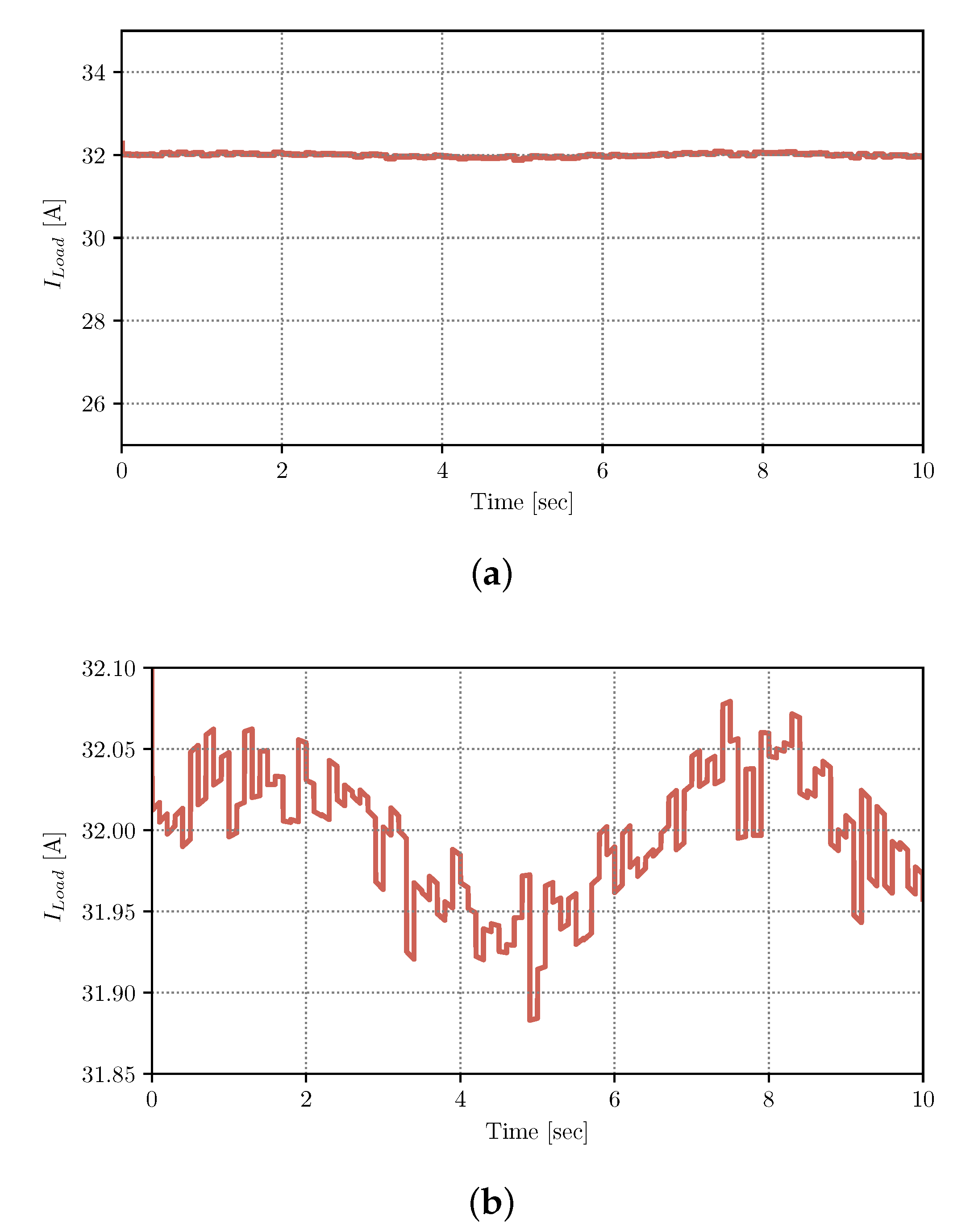
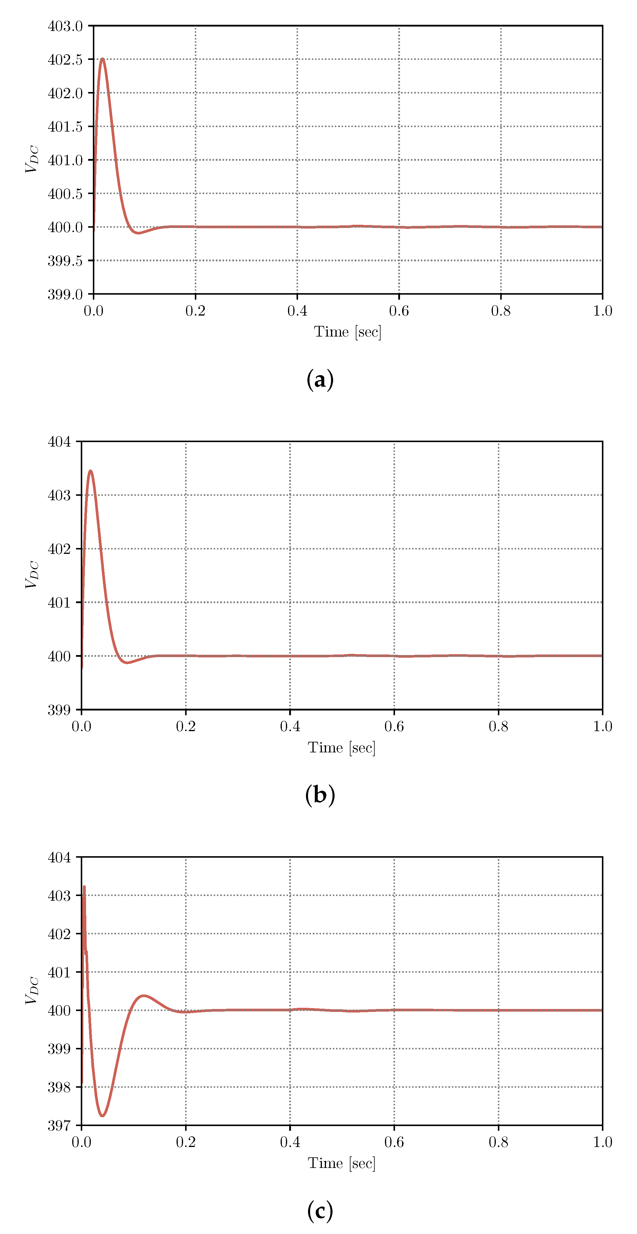
4.3. Integration of the Battery in Microgrid

The battery model is now connected as a load in the proposed DC microgrid with non-linear control. The output current of the EV battery is depicted in Figure 6. This current load returns back in the connected microgrid model. There is also a look-up table that calculates the battery’s internal resistance value, depending on the battery pack output voltage, which was obtained from [33]. Note that the microgrid has three input voltages sources, which are: PV (150 V), a storage battery (350 V), and a supercapacitor (136 V).
Accordingly, each of the cells is modeled, and then each current will be added together.
In this case, the assumed S O C is 50%. Figure 6a shows that the output current is almost constant. It is observed in Figure 6b that the current oscillates between 31.90 A and 32.05 A, which are very close values from the reference value of 32 A.
Three different values of the output current I L o a d were evaluated to assess the impact of the microgrid’s output voltage: 12 A, 16 A, and 32 A. These values are selected, since they correspond to the typical currents for charging an EV in Level 1.
Figure 7 illustrates the output voltage, where the expected final value is 400 V. In all cases, it is observed that there are a few fluctuations of the output before reaching the final value of 400 V. Moreover, note that, with an increase of I L o a d , the deviation from the reference value increases. This is expected since the microgrid’s stability is affected by the fluctuation, in this case of the Load.
The output voltage stabilizes quickly (less than 0.2 s). The voltage deviations are 0.63%, 0.88%, and 0.93%, for I L o a d = 12 A, 16 A, and 32 A, respectively. For all of the cases, the deviations are minimal, and none of them exceed 1%. Therefore, it can be concluded that the non-linear control works satisfactorily in a DC microgrid when considering the charging of an EV.

4.4. Discussion

The need for more sustainable transportation and electricity generation will introduce significant challenges by implementing DC microgrids and the massive introduction of EVs.
This work has assessed the impact of charging EVs in DC microgrids by using non-linear control. The modeling of the batteries is more accurate than in [25], where a simplified model for batteries was considered. For both of the models, the non-linear control results in the adequate stability of the systems, with less than 1% of voltage deviations. In this work, it was observed that the output current suffer some distortion, but is minimal when compared to the reference value.
Some considerations need to be accounted for in implementing this model. Appropriate DC-DC converters should be used to implement this non-linear control. Moreover, in real implementation, some variation from the presented results could be observed, since the modeling is not 100% accurate to the reality.

5. Conclusions

This paper assesses the impact of the EV load in DC microgrids’ operation, which is subject to nonlinear control theory. The EV battery was based on a formal model and simulated. The proposed DC microgrid included PV generation, electric battery storage, and a supercapacitor. The proposed scheme was performed in Simulink.
Various values of the initial S O C and the output current are simulated to assess the DC microgrid’s impact. The DC microgrid voltage reaches the expected value of 400 V, and deviations of 0.63%, 0.88%, and 0.93% are observed, for I L o a d = 12 A, 16 A, and 32 A, respectively. For all of the cases, the deviations are minimal, and none of them exceed 1%. Thus, the nonlinear control ensures the DC microgrid’s stability, when considering the load of the EV charging.

Author Contributions

Conceptualization, J.-M.C.; Data curation, P.S., R.E.; Formal analysis, P.S., R.E.; Investigation, P.S., R.E.; Methodology, P.S., R.E.; Supervision, J.-M.C.; Validation, J.-M.C., A.G.-Z.; Writing—original draft, P.S., R.E.; Writing—review & editing, J.-M.C., A.G.-Z. All authors have read and agreed to the published version of the manuscript.

Funding

This paper belongs to the project SIS.JCG.19.03 from Universidad de las Américas—Ecuador.

Institutional Review Board Statement

Not applicable.

Informed Consent Statement

Not applicable.

Data Availability Statement

Data available on request.

Conflicts of Interest

The authors declare no conflict of interest.

Abbreviations

The following abbreviations are used in this manuscript:
CO 2 Carbon dioxide
DGDistributed Generation
ESSEnergy Storage System
EVElectric Vehicle
RERenewable Energy
PCC   Point of Common Coupling
PIProportional integral
PVPhotovoltaic
V2GVehicle-to-Grid
SOCState-of-Charge

References

  1. Lotfi, H.; Khodaei, A. AC versus DC microgrid planning. IEEE Trans. Smart Grid 2017, 8, 296–304. [Google Scholar] [CrossRef]
  2. Olivares, D.E.; Mehrizi-Sani, A.; Etemadi, A.H.; Cañizares, C.A.; Iravani, R.; Kazerani, M.; Hajimiragha, A.H.; Gomis-Bellmunt, O.; Saeedifard, M.; Palma-Behnke, R.; et al. Trends in microgrid control. IEEE Trans. Smart Grid 2014, 5, 1905–1919. [Google Scholar] [CrossRef]
  3. Dragicevic, T.; Lu, X.; Vasquez, J.C.; Guerrero, J.M. DC Microgrids—Part I: A Review of Control Strategies and Stabilization Techniques. IEEE Trans. Power Electron. 2016, 31, 4876–4891. [Google Scholar] [CrossRef] [Green Version]
  4. Justo, J.J.; Mwasilu, F.; Lee, J.; Jung, J.W. AC-microgrids versus DC-microgrids with distributed energy resources: A review. Renew. Sustain. Energy Rev. 2013, 24, 387–405. [Google Scholar] [CrossRef]
  5. Sanjeev, P.; Padhy, N.P.; Agarwal, P. Peak energy management using renewable integrated DC microgrid. IEEE Trans. Smart Grid 2018, 9, 4906–4917. [Google Scholar] [CrossRef]
  6. Liu, J.; Lu, X.; Wang, J. Resilience Analysis of DC Microgrids Under Denial of Service Threats. IEEE Trans. Power Syst. 2019, 34, 3199–3208. [Google Scholar] [CrossRef]
  7. Dragičević, T.; Lu, X.; Vasquez, J.C.; Guerrero, J.M. DC Microgrids—Part II: A Review of Power Architectures, Applications, and Standardization Issues. IEEE Trans. Power Electron. 2016, 31, 3528–3549. [Google Scholar] [CrossRef] [Green Version]
  8. Ghiasi, M.I.; Golkar, M.A.; Hajizadeh, A. Lyapunov Based-Distributed Fuzzy-Sliding Mode Control for Building Integrated-DC Microgrid with Plug-In Electric Vehicle. IEEE Access 2017, 5, 7746–7752. [Google Scholar] [CrossRef]
  9. Aluisio, B.; Bruno, S.; De Bellis, L.; Dicorato, M.; Forte, G.; Trovato, M. DC-Microgrid operation planning for an electric vehicle supply infrastructure. Appl. Sci. 2019, 9, 2687. [Google Scholar] [CrossRef] [Green Version]
  10. Travaillé, P.; Benamar, A.; Clairand, J.M.; Escrivá-Escrivá, G. Operation of DC Microgrids Considering Different Strategies of Electric Vehicle Charging. In Proceedings of the 2020 IEEE ANDESCON, Quito, Ecuador, 13–16 October 2020; pp. 1–5. [Google Scholar] [CrossRef]
  11. Farrokhabadi, M.; Konig, S.; Canizares, C.A.; Bhattacharya, K.; Leibfried, T. Battery Energy Storage System Models for Microgrid Stability Analysis and Dynamic Simulation. IEEE Trans. Power Syst. 2018, 33, 2301–2312. [Google Scholar] [CrossRef]
  12. Zia, M.F.; Elbouchikhi, E.; Benbouzid, M. Optimal operational planning of scalable DC microgrid with demand response, islanding, and battery degradation cost considerations. Appl. Energy 2019, 237, 695–707. [Google Scholar] [CrossRef]
  13. Ceraolo, M. New dynamical models of lead-acid batteries. IEEE Trans. Power Syst. 2000, 15, 1184–1190. [Google Scholar] [CrossRef] [Green Version]
  14. Kim, G.H.; Pesaran, A.; Spotnitz, R. A three-dimensional thermal abuse model for lithium-ion cells. J. Power Sources 2007, 170, 476–489. [Google Scholar] [CrossRef]
  15. Tremblay, O.; Dessaint, L.A.; Dekkiche, A.I. A generic battery model for the dynamic simulation of hybrid electric vehicles. In Proceedings of the 2007 IEEE Vehicle Power and Propulsion Conference, Arlington, TX, USA, 9–12 September 2007; pp. 284–289. [Google Scholar]
  16. Motapon, S.N.; Lupien-Bedard, A.; Dessaint, L.A.; Fortin-Blanchette, H.; Al-Haddad, K. A Generic Electrothermal Li-ion Battery Model for Rapid Evaluation of Cell Temperature Temporal Evolution. IEEE Trans. Ind. Electron. 2017, 64, 998–1008. [Google Scholar] [CrossRef]
  17. Cicconi, P.; Landi, D.; Germani, M. Thermal analysis and simulation of a Li-ion battery pack for a lightweight commercial EV. Appl. Energy 2017, 192, 159–177. [Google Scholar] [CrossRef]
  18. Berrueta, A.; Urtasun, A.; Ursúa, A.; Sanchis, P. A comprehensive model for lithium-ion batteries: From the physical principles to an electrical model. Energy 2018, 144, 286–300. [Google Scholar] [CrossRef] [Green Version]
  19. Khan, A.B.; Choi, W. Optimal Charge Pattern for the High-Performance Multistage Constant Current Charge Method for the Li-Ion Batteries. IEEE Trans. Energy Convers. 2018, 33, 1132–1140. [Google Scholar] [CrossRef]
  20. Ma, Y.; Duan, P.; Sun, Y.; Chen, H. Equalization of Lithium-Ion Battery Pack Based on Fuzzy Logic Control in Electric Vehicle. IEEE Trans. Ind. Electron. 2018, 65, 6762–6771. [Google Scholar] [CrossRef]
  21. Hasan, R.; Scott, J. Comments on ’State of Charge-Dependent Polynomial Equivalent Circuit Modeling for Electrochemical Impedance Spectroscopy of Lithium-Ion Batteries’. IEEE Trans. Power Electron. 2020, 35, 4448. [Google Scholar] [CrossRef] [Green Version]
  22. Lai, X.; He, L.; Wang, S.; Zhou, L.; Zhang, Y.; Sun, T.; Zheng, Y. Co-estimation of state of charge and state of power for lithium-ion batteries based on fractional variable-order model. J. Clean. Prod. 2020, 255, 10319–10329. [Google Scholar] [CrossRef]
  23. Lyu, C.; Lai, Q.; Ge, T.; Yu, H.; Wang, L.; Ma, N. A lead-acid battery’s remaining useful life prediction by using electrochemical model in the Particle Filtering framework. Energy 2017, 120, 975–984. [Google Scholar] [CrossRef]
  24. Zou, C.; Hu, X.; Dey, S.; Zhang, L.; Tang, X. Nonlinear Fractional-Order Estimator With Guaranteed Robustness and Stability for Lithium-Ion Batteries. IEEE Trans. Ind. Electron. 2018, 65, 5951–5961. [Google Scholar] [CrossRef]
  25. Benamar, A.; Travaillé, P.; Clairand, J.M.; Escrivá-Escrivá, G. Non-Linear Control of a DC Microgrid for Electric Vehicle Charging Stations. Int. J. Adv. Sci. Eng. Inf. Technol. 2020, 10, 593–598. [Google Scholar] [CrossRef] [Green Version]
  26. Boukhezzar, B.; Siguerdidjane, H. Comparison between linear and nonlinear control strategies for variable speed wind turbines. Control Eng. Pract. 2010, 18, 1357–1368. [Google Scholar] [CrossRef]
  27. Perez, F.; Iovine, A.; Damm, G.; Galai-Dol, L.; Ribeiro, P. Regenerative Braking Control for Trains in a DC MicroGrid Using Dynamic Feedback Linearization Techniques. IFAC-PapersOnLine 2019, 52, 401–406. [Google Scholar] [CrossRef]
  28. Perez, F.; Iovine, A.; Damm, G.; Galai-Dol, L.; Ribeiro, P.F. Stability Analysis of a DC MicroGrid for a Smart Railway Station Integrating Renewable Sources. IEEE Trans. Control Syst. Technol. 2020, 28, 1802–1816. [Google Scholar] [CrossRef]
  29. Siad, S.B.; Malkawi, A.; Damm, G.; Lopes, L.; Dol, L.G. Nonlinear control of a DC MicroGrid for the integration of distributed generation based on different time scales. Int. J. Electr. Power Energy Syst. 2019, 111, 93–100. [Google Scholar] [CrossRef] [Green Version]
  30. Iovine, A.; Jim, M.; Damm, G. Nonlinear Control for DC MicroGrids Enabling Efficient Renewable Power Integration and Ancillary Services for AC grids. IEEE Trans. Power Syst. 2018, 8950, 1–10. [Google Scholar] [CrossRef]
  31. Qnovo. Inside the battery of a Nissan Leaf. Available online: https://www.geoenergia.gob.ec/ (accessed on 11 May 2021).
  32. Liu, Y.; Liao, G.Y.; Lai, M.C. Development and validation of a lithium-ion polymer battery cell model for 12V SLI battery applications. In Proceedings of the ASME 2018 International Design Engineering Technical Conferences and Computers and Information in Engineering Conference, Quebec City, QC, Canada, 26–29 August 2018; Volume 3, pp. 1–10. [Google Scholar] [CrossRef]
  33. Liu, Y.; Liao, Y.G.; Lai, M.C. Lithium-Ion Polymer Battery for 12-Voltage Applications: Experiment, Modelling, and Validation. Energies 2020, 13, 638. [Google Scholar] [CrossRef] [Green Version]
  34. Yao, L.W.; Aziz, J.A.; Kong, P.Y.; Idris, N.R.N. Modeling of lithium-ion battery using MATLAB/simulink. In Proceedings of the IECON 2013—39th Annual Conference of the IEEE Industrial Electronics Society, Vienna, Austria, 10–13 November 2013; pp. 1729–1734. [Google Scholar]
  35. Liu, Y.; Liao, Y.G.; Lai, M.C. Modeling and Validation of Lithium-Ion Polymer SLI Battery (No. 2019-01-0594); SAE International: Troy, MI, USA, 2019. [Google Scholar]
Figure 1. Proposed DC Microgrid blocks diagram.
Applsci 11 04415 g001
Figure 2. Proposed Circuit of the Microgrid.
Applsci 11 04415 g002
Figure 3. Modeling of a battery cell with Simulink.
Applsci 11 04415 g003
Figure 4. The proposed structure of battery consisting of cells connected in series and parallel.
Applsci 11 04415 g004
Figure 5. Output of the battery voltage with: (a) S O C = 0.1; (b) S O C = 0.5; and, (c) S O C = 0.9.
Applsci 11 04415 g005
Figure 6. Output current of the EV battery with: (a) Plot that shows almost constant current; (b) Zoomed-in plot revealing a small current oscillation.
Applsci 11 04415 g006
Figure 7. Output voltage of the microgrid with: (a) I L o a d = 12 A; (b) I L o a d = 16 A; and, (c) I L o a d = 32 A.
Applsci 11 04415 g007
Publisher’s Note: MDPI stays neutral with regard to jurisdictional claims in published maps and institutional affiliations.

