Article

Semi-Active System of Vehicle Vibration Damping

by
Wiesław Grzesikiewicz
and
Michał Makowski
*
Institute of Vehicles and Construction Machinery Engineering, Warsaw University of Technology, 84 Narbutta Street, 02-524 Warsaw, Poland
*
Author to whom correspondence should be addressed.
Appl. Sci. 2021, 11(10), 4577; https://doi.org/10.3390/app11104577
Submission received: 2 April 2021 / Revised: 11 May 2021 / Accepted: 14 May 2021 / Published: 17 May 2021
(This article belongs to the Section Mechanical Engineering)

Abstract

:
This article discusses the vibration of a vehicle equipped with four semi-active dampers. The friction forces generated in these dampers have crucial influence on the intensity of the vehicle vibration. To estimate the effect of the vehicle vibration damping, a criterial function depending on the values of these forces has been selected. Solving the problem has the purpose of determining four values of the forces at which the criteria function reaches the minimum at any moment. On the basis of the above, signals for the devices controlling the operation of the semi-active dampers are determined. In this work, the analysis of the discussed problem was conducted in regard to the method for determining the optimal force values. Moreover, the results of the simulation of the vibration of the vehicle equipped with semi-active magneto-rheological dampers are presented. In addition, the analysis of the influence of the form of the criterial function on the vehicle vibration damping efficiency is proposed. Based on the tests carried out on the vehicle with MR dampers, the comfort index improved by 51.6%, compared to the classic suspension.

1. Introduction

This article discusses the vehicle vibration induced by uneven road surfaces and also by the inertial forces affecting the body. As a result of such a vibration, the driving comfort deteriorates and the dynamic load on the vehicle structure increases. Moreover, wheel pressure on the road surface changes (change in the dynamic loads in the suspension), which can contribute to slippage during acceleration, braking, or driving on a curve. In order to reduce vehicle body vibration, various kinds of devices are commonly used, dispersing the energy, known as vibration dampers.
The problem area related to applying the semi-active dampers to reduce the vibration of vehicles, machines or buildings has long been considered. However, in recent years, technical conditions have emerged that enable practical implementation of such a way of reducing vehicle vibration [1,2]. There has been development in the field of controlled structures based on smart materials. These materials include magnetorheological fluids [3,4], electrorheological fluids [5,6] and vacuum-packed particles [7].
At the end of the 20th century, magnetorheological fluid technology was developed. That laid the groundwork for the development of magnetorheological dampers (MR dampers). In the beginning, the technology was developed by the LORD Corporation, Cary, North Carolina, USA. MR dampers have been used in human prostheses and vehicle seats [8,9]. In the following years, further research related to the development of MR dampers began, which resulted in new solutions presented in publications [10,11,12]. Currently, controlled MR dampers are used in different fields: damping vibrations of buildings [13,14], reducing vibrations of washing machines [15,16], in suspensions of high-speed trains [17,18] and in automotive suspensions [19,20,21]. These conditions were created due to the possibility of using on-board computers with high computing power and semi-active dampers.
An important problem is the determination of the control signal for semi-active dampers. For this purpose, different methods were developed where the control signal is determined on the basis of the measurement signals. In multi-body systems, Zero Residual Vibration-Derivative methods [22,23] are used to determine the control signal. Another solution to the problem is to use Hybrid Prediction Control [24,25]. Sky-hook and ground-hook methods [26,27] are common in semi-active suppression of vehicle vibration. The authors of the work developed original methods of minimizing acceleration in a selected point of the car body [11].
In the presented system, the vibration control of the vehicle is carried out by means of semi-active dampers based on the control signals from the LVDT displacement sensors. The original mechatronic system, based on a dedicated algorithm for determining the control signals, was developed for control. Controlling the frictional force in vibration dampers was adopted to reduce the vertical accelerations affecting the vehicle passengers. In the discussed solution, a controlled magnetorheological damper (MR) was used.

2. MR Damper

A magnetorheological damper (MR) has a varying damping force that changes due to the changing current values. In such a damper, an enclosed coil generates the magnetic field. Then, the change in the friction force is induced by means of controlling the intensity of the magnetic field of the damper coil. One feature of magnetorheological fluid is its changing viscosity ensued by the magnetic field. Resulting from variations in the viscosity of the MR fluid, a change in the damping forces takes place. Thus, changes in the current intensity in the electronic system enable controlling changes in the dissipated energy. The developed MR damper was subjected to tests. Figure 1 shows the original design of the magnetorheological damper (MR-IP damper), developed at the Institute of Vehicles, Warsaw University of Technology (Instytut Pojazdów Politechniki Warszawskiej). The damper was filled with an MR fluid (3), the viscosity of which varies according to the magnetic field (5), generated by the coil (1), and enclosed in the piston (6). During the piston motion, the fluid is pressed through the orifices (2) in the piston. In the discussed solution, the housing (4) does not move; only the piston gets displaced and (6) mounted onto the piston rod (7). At that point, the change in the current intensity affects the change in the damping force acting on the damper’s piston rod.
The developed MR-IP damper design served the purpose of conducting the property tests. As a result of the experimental research, the dissipative characteristic of the MR damper were determined. Figure 2 illustrates the conducted tests on the plane: force–displacement and force–velocity, where the coil of the MR damper was supplied with the 2 A current, and with no supply (0 A). Experimental research was conducted with the kinematic excitation at the frequency of 0.8 Hz with 0.18 m amplitude.
The diagrams show the change in the frictional force value in the case of tests conducted under no-supply conditions (0 A). The frictional force value at the level of 500 N was obtained, whereas in the case of the tests under the condition of the coil supply 2 A, the frictional force value was at the level of 1500 N. As far as the conducted tests are concerned, it has been postulated that controlling the frictional force in dampers is possible in the course of changing the supply current. Then, during the varying current intensity in the range of 0–2 A, controlling the frictional force value will be possible. In the shown force–velocity characteristics, a hysteresis loop can be observed with regard to the tests conducted under no-supply conditions, as well as with the 2 A current. Figure 2 shows only the limit values of the frictional forces. The change in the friction forces in the range of 0–2 A is not linearly dependent on the current changes, which should be taken into account in the algorithm for selecting the friction forces.
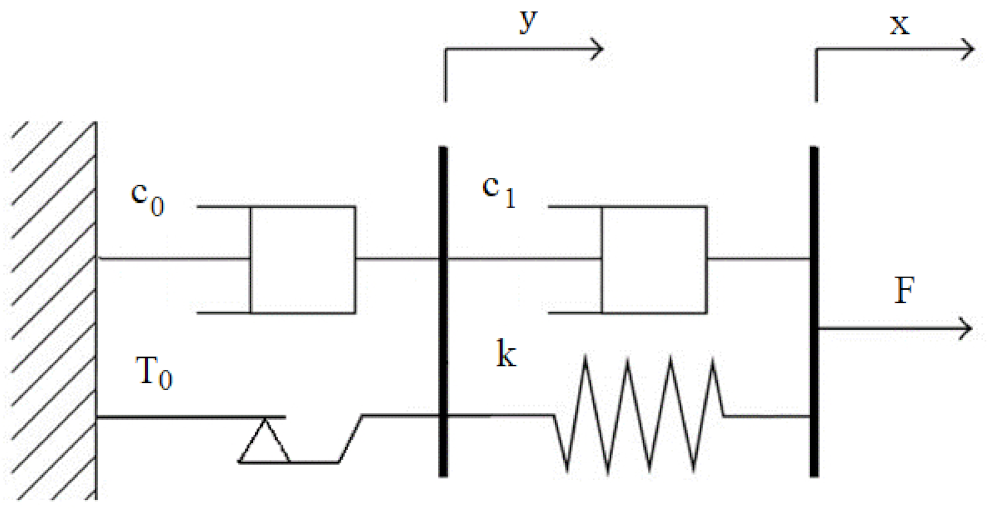
The test results served the purpose of developing the model of the controlled MR damper. In the subject literature, the Bouc–Wen model [28,29,30] is most frequently used to model this type of damper. In this work, a model in the form of a rheological structure was used, presented in Figure 3, originally proposed by Grzesikiewicz. This structure shows the viscoplastic features of the MR damper. The discussed model is characterized by four parameters that are relatively easy to determine on the basis of the experimental research results.
The mathematical model describing the MR damper is as follows:
F =   c 1 ( x ˙ y ˙ ) + k x y
c 0 + c 1 y ˙ + τ T 0 = c 1 x ˙ + k x y
τ sign   y ˙ , 1 , + 1 , when when y ˙ 0 y ˙ = 0
where T 0 , c 0 , c 1 , k —model parameters, which are positive numbers characterizing the viscous–elastic features of the structure, x , y —coordinates of the model.
The values of the parameters ( T 0 , c 0 , c 1 , k ) are related to the current of the MR damper. In the presented MR damper model, the friction force depends on the velocity of deformation x ˙ .
On the basis of the experimental research results, the identification of the damper parameters was conducted. In the course of the identification of the model parameters, it was observed that, along with the change in the current within the range of 0–2 A, the T 0 parameter changes the most. For the sake of numerical tests, the assumption was adopted that the changing current will ensue the variation of only one parameter with the remaining parameters being unchanged. Figure 4 shows the results of the numerical research that corresponds to the experimental research at 0 A and 2 A.
On the basis of the conducted numerical research, the dissipative characteristics of the MR damper model were obtained. Similar to the characteristics regarding the experimental research, ranges of approx. 500 N of the frictional force were obtained at the current intensity 0 A, whereas in the case of the 2 A supply, the value of frictional forces of approx. 1500 N was obtained. The hysteresis loop can also be discerned, which could be observed in the results of the experimental research. Figure 5 shows the comparison of results of the experimental and numerical research on the MR damper with 2A current.
As a result of the conducted tests of the MR damper and identification of the damper model, a numerical model was developed. The performed simulation tests validated the assumption that the proposed model may be utilized in numerical research of the MR damper. The determined damper parameters can be used in a model to simulate the tests of the damper supplied with the variable current value in the range of 0–2 A. The proposed damper model was used during further numerical research connected with reduction of the vehicle vibrations. Considering the inconclusive solutions that can be obtained on the basis of the dissipative characteristics of the damper, regularization (simplification of the characteristic) was carried out. This characteristic was used to control the value of damping forces.
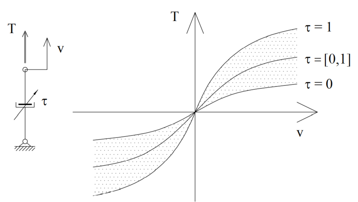
The energy-related features of the semi-active damper are characterized by means of the parametric relationship (f) between the force generated in the damper (friction force) (T) and the velocity of its deformation (v), whereas the form of this relationship depends on parameter τ 0 , 1 , which can be written using the following formula:
T = f v ; τ ,   τ 0 , 1 ,
Schematic plot of such a characteristic is shown in Figure 6. In the relationship under consideration, parameter τ represents a physical quantity by which the semi-active damper’s dissipative features can be controlled, which is shown in Figure 4. The description above ensures that friction force T in the semi-active damper can assume values from the range determined by the following relationship:
T T min v , T max v ,   v R 1 ,
if
T min v = f v ; 0 ,                                 when   v 0 f v ; 1 ,                                 when   v < 0 T max V = f v ; 1 ,                                 when   v 0 f v ; 0 ,                                   when   v < 0 ,
Relationships (5) and (6) can be written in an altered form:
T v ϑ v R 1 ,
ϑ v = T R 1 : T min v T T max v ,
By means of Formula (8), delineation Ω is defined as follows:
Ω V = T R 4 : T i ϑ v i ,   i = 1 , , 4 R 4 ,
if
T R 4 —vector of the friction forces in four dampers,
  • V R 4 —vector of the deformation velocity of four dampers.
  • Delineation Ω determines the set of permissible vectors of the friction forces T R 4 depending on the velocity vector V R 4 defining velocity values of damper deformation.
The optimization problem discussed subsequently is connected with determining the optimal vector T opt Ω V for which the criterial function K :   R 4 R 1 reaches the minimal value. Thus, the vector is determined, fitting into the following relationship:
T opt Arg   min T Ω V K T ,
A detailed description of this relationship will be given further on in this paper.

3. Vehicle Model

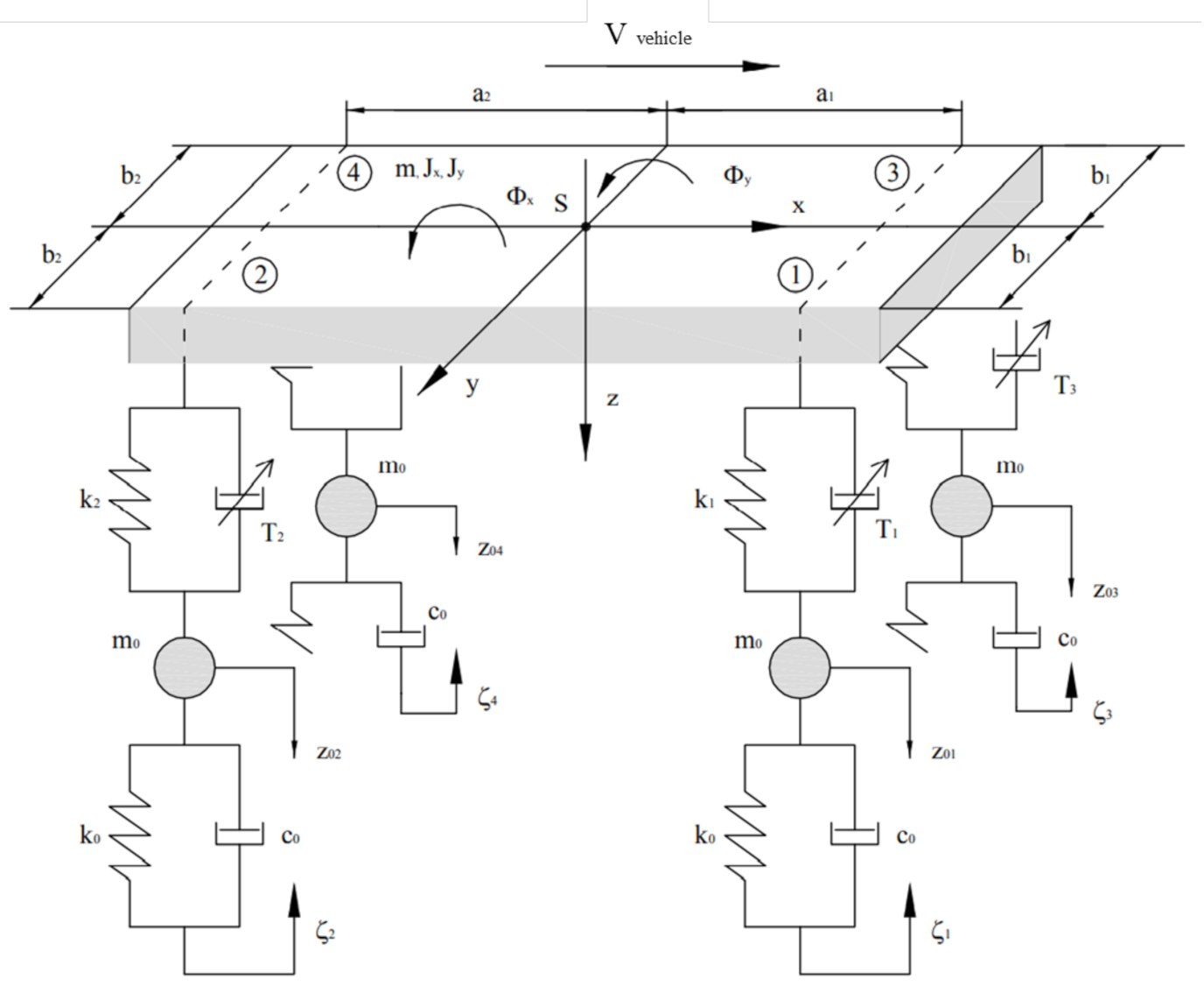
The considered mathematical vehicle model serves the purpose of analyzing the vibration in the vertical plane. Figure 7 shows the scheme of the mechanical system, which was adopted for the equations describing the vehicle vibration to be formulated.
In order to simplify this description, the following were adopted:
Elastic suspension elements have linear characteristics;
Vehicle wheels are in constant contact with the road surface;
Elastic-dissipative features of the suspension are mapped with the help of elements located directly above the wheels;
The vehicle mass is distributed symmetrically relative to the longitudinal axis.
To describe the vehicle vibration, coordinates were selected that determine the vehicle displacements relative to the equilibrium position. Figure 7 shows the selected marked coordinates and the basic model parameters. The equations of the vehicle vibration are defined with the following formulae:
m z ¨ + i = 1 4 S i + T i = 0 ,
J x Φ x ¨ + b 1 S 1 + T 1 + b 2 S 2 + T 2 b 1 S 3 + T 3 b 2 S 4 + T 4 + M 1 S + M 2 S = M x ,
J y Φ y ¨ a 1 S 1 + T 1 + a 2 S 2 + T 2 a 1 S 3 + T 3 + a 2 S 4 + T 4 = M y ,
i = 1 4 m 0 z ¨ 0 i i = 1 4 S i + T i + i = 1 4 S 0 i + T 0 i + i = 1 4 F i S = 0 ,
where S i ,   T i ,   i = 1 , , 4 —elastic and dissipative forces acting between the i-th wheel and the suspension, so that
S i = k i U i ,   T i = f V i ; I i ,   i = 1 , , 4 ,
forces resulting from the tire deformation
  S 0 i = k 0 i U 0 i ,   T 0 i = c 0 i V 0 i ,   i = 1 , , 4 ,
U 1 = z + b 1 Φ x a 1 Φ y z 01 U 2 = z + b 2 Φ x + a 2 Φ y z 02 U 3 = z b 1 Φ x a 1 Φ y z 03 U 4 = z b 2 Φ x + a 2 Φ y z 04 ,
V 1 =   z ˙ + b 1 Φ ˙ x a 1 Φ ˙ y z ˙ 01 V 2 = z ˙ + b 2 Φ ˙ x + a 2 Φ ˙ y z ˙ 02 V 3 = z ˙ b 1 Φ ˙ x a 1 Φ ˙ y z ˙ 03 V 4 = z ˙ b 2 Φ ˙ x + a 2 Φ ˙ y z ˙ 04 ,
U 0 i = z 0 i + ξ i ,   V 0 i = z ˙ 0 i + ξ ˙ i ,   i = 1 , , 4 ,
M 1 S , M 2 S —moments of the force resulting from twisting of the front and rear stabilizers.
M 1 S = κ 1 Φ x z 01 z 03 2 b 1   M 2 S = κ 2 Φ x z 02 z 04 2 b 2   ,
if κ 1 ,   κ 2 —rigidity of the front and rear stabilizers;
The stabilizers’ forces acting on the wheel
F 1 S = F 3 S = M 1 S 2 b 1 ,   F 2 S = F 4 S = M 2 S 2 b 2 ,
The remaining symbols in the figure denote the following:
  • V vehicle —vehicle velocity.
  • M x ,   M y moments of the inertial force acting on the vehicle body during transient ( V vehicle const . ) .
Let it be assumed, that functions ξ i ,   i = 1 , , 4 describing kinematic vibration forcing, as well as the function of velocity V vehicle , are set.
The above-formulated task regarding vehicle vibrations has a solution only when the vector of parameters τ R 4   (Figure 6) is known at any moment of time; then, on the basis of Formula (4), the values of forces in the dampers can be determined as follows:
T i = f v i ,   τ i ,
Parameters τ i   i = 1 , , 4 are set in the system of damper control. The description of this systems are presented in the next section.
In the considerations therein, the following denotations will be used:
H = 1 1 1 b 1 b 2 b 1 a 1 a 2 a 1 1 b 2 a 2 R 3 × 4 ,
h = 1 α 1 α R 4 ,   α = b 1 b 2   ,
An observation can be made that the equality condition is satisfied:
Hh = 0 ,
P = HS + C R 3 ,   S = S 1 , S 2 , S 3 , S 4 T R 4 ,
C = 0 ,   M 1 S + M 2 S M x , M y T ,
Using the above denotations in Equation (11) enabled the obtaining of the set of three equations describing the acceleration of the vehicle body:
B + P + HT = 0 ,
B = m z ¨ ,   J x Φ ¨ x ,   J y Φ ¨ y T R 3 ,
In accordance with the adopted assumptions, the vector of force S R 4 (Formula (15)), determines changes in the load of the elastic elements of the suspension relative to their static load in the state of equilibrium.

4. Model of the Control System

In the system of the damper control, signals are processed that represent the physical quantities characterizing the vehicle state. In the subsequent discussion, denotations of physical quantities and corresponding signals are the same.
The central part of the considered control system is a programmable controller, where the signal vector τ opt R 4 is determined, corresponding to the optimal vector of the friction forces T opt defined by the relationship in Formula (15). Fundamentals applied to formulate this relationship are provided by criterial function 𝒦, defining the influence of the friction forces on the intensity of the vehicle vibration. In this work, the intensity of the vehicle vibration will be estimated on the basis of vector A R 3 defining the acceleration of the vehicle body:
A = M 1 P + HT ,
where vector of forces P R 3 described with the Formula (26),
  • M —matrix of the body inertia.
M R 3   x   3 ,   M = diag m , J x , J y ,
Formula (30) determines the relationship between the vectors of friction forces T R 4 and accelerations of the vehicle body A R 3 .
On the basis of the above, the first criterial function is determined, which sets the norm for the acceleration vector A R 3 according to the following formula:
K 1 T = 1 2 A T A ,
Hence, after taking into account Formula (30), the following is obtained:
K 1 T = 1 2 P + HT T M 2 P + HT ,
and after transformations, there are:
K 1 T = 1 2 TDT + d T T + 1 2 P T M 2 P ,
if
D R 4 × 4 ,   D = H T M 2 H ,
d R 4 ,   d = H T M 2 P .
The optimization task is formulated in the following way: vector T Ω V needs to be determined for which the value of function K 1 is the smallest in the set of vectors Ω V described with Formula (9).
Taking into account that function K 1 and set Ω V are convex allows for concluding that the above task has a solution; because matrix D is not strictly convex—which ensues from Formulae (25) and (35)—the solution to this task may be ambiguous. This means that in set Ω V , there exists a subset of vectors for which the values of function K 1 are the same and equal to the minimum.
Thus, the optimizing issue considered herein comes down to determining a subset of vectors T , as mentioned before, and selecting one of those T opt . This task can be rendered as follows:
T opt Arg   min T Ω V K 1 T   ,
For the vector of forces T opt Ω V so determined, the norm of the vector of body accelerations, denoted with Formula (32), reaches the minimum. It needs to be noted that vector T opt , selected in such a way, changes along the vector U ,   V R 3 because the force vector P R 3 (Formula (26)) depends on them and the set Ω (Formula (8)). This means, that relationship (37) is non-stationary because vectors U ,   V change over time.
The method of determining solution (37) can be found further in this work. Here, the second criterial function is presented, defined on the basis of the Karnopp principle [26,27] according to which effective damping of the vehicle vibration can be achieved by means of the forces that depend on the vector of the body velocity V O :
F sky = C sky V O R 3 ,
if
V O = z ˙ ,   φ x ˙ ,   φ y ˙ T R 3   ,
  C sky = diag   c z ,   c x ,   c y R 3 R 3   x   3   ,
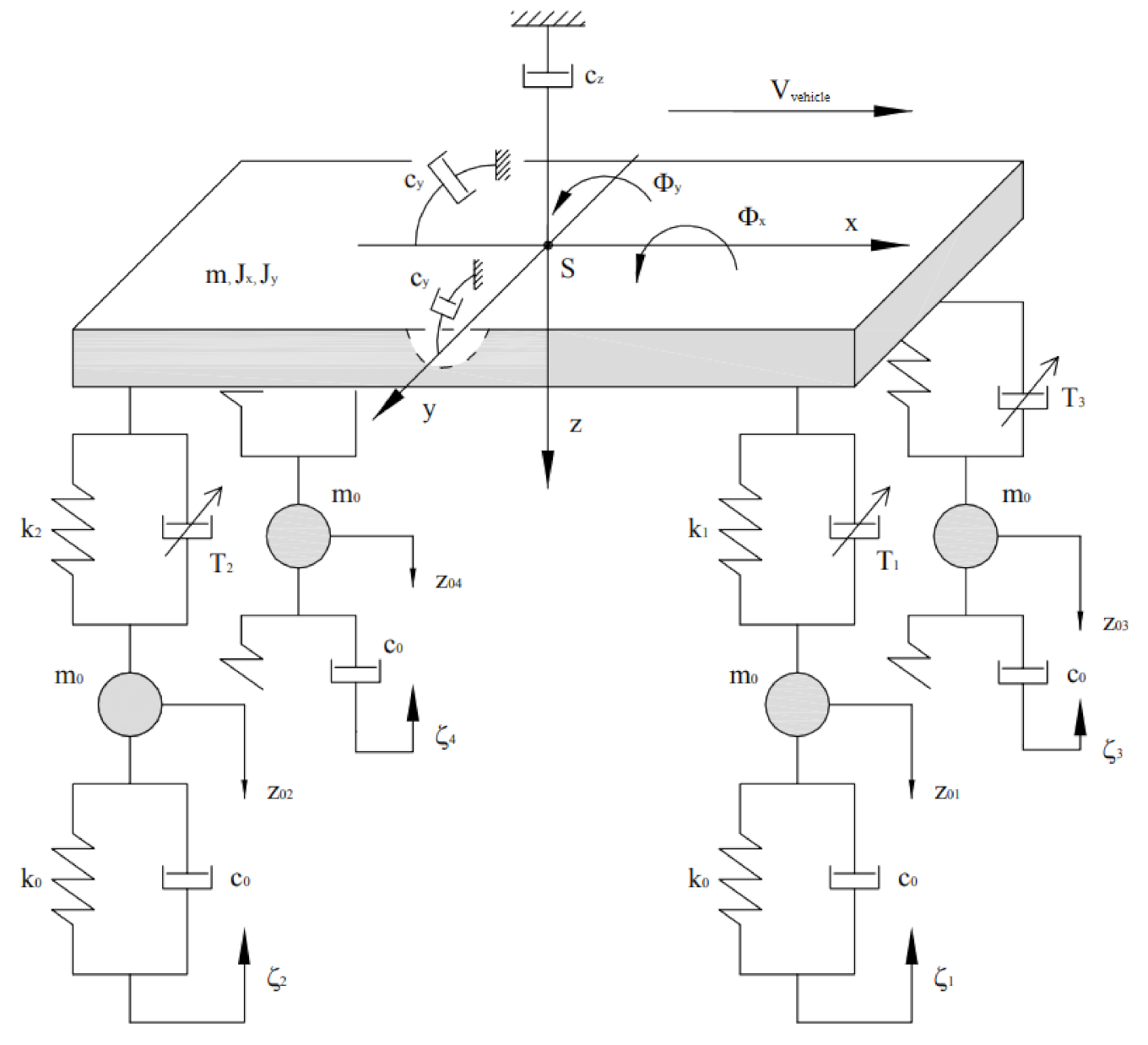
The force determined in such a way is known as sky hook. Figure 8 shows a schematic model of the vehicle with the damper control according to the sky-hook strategy.
The relationship of such a force ( F sky ) by means of four semi-active dampers is possible when the following relationships are fulfilled:
F sky = HT ,   T Ω H T V O ,
The relationships (41), however, can be fulfilled only in particular states of the vehicle body motion. For this reason, selecting of force T R 4 is considered, which is the one that best maps the action of force F sky R 3 . With the task determined in such a way, the second criterial function can be defined:
  K sky T = 1 2 HT F sky T HT F sky ,
that sets the measure for the vector deviation T R 4 from the set of solutions to equation HT F sky = 0 . After the appropriate transformation of Formula (42), the following is obtained:
K sky T = 1 2 T T D sky T T T d sky + 1 2 F sky 2 ,
if
D sky = H T H R 4 ,   d sky = H T F sky R 4 ,
The observation can be made that the form of criterial function K sky is analogous to the form of criterial function K 1 . Moreover, criterial function K 2 is also convex but not strictly convex and also non-stationary because force F sky depends on the body velocity. Thus, vector T sky Ω V , which optimally translates the action of force F sky R 3 , is determined by means of the relationship from Formula (37):
T sky Arg   min T Ω v K sky T ,
In further considerations, a method for determination of optimal vectors of friction forces, defined by relationships (37) and (45), is presented.

4.1. Solution to the Optimization Task

A homogenous description of both abovementioned tasks is considered here. Let the following criterial function be the focus:
K T = 1 2 T T DT + d T T ,
the matrix of which D R 4   x   4 is semi-positive and its nucleus is determined by the one-dimensional space:
kerD = T R 4 : T = ξ h ,   ξ R 1 ,
where vector h R 4 is defined in Formula (24).
The optimal solution is sought in convex set Ω V R 4 and is determined by the following relationship:
T opt Arg   min T Ω V K T ,
The set of optimal vectors so determined is not empty, and each pair of vectors satisfies the condition T 1 T 2 kerD .
On the basis of the Kuhn–Tucker theorem, and after taking into account the specific form of the set Ω (9), the conditions are obtained, which should be satisfied by relationship solution (48):
DT opt + d = λ ,
T opt = π Ω T opt ρ λ   ,
  • λ R 4 —of such vectors, that λ i 0 , i = 1 , , 4 ;
  • ρ R 1 —any positive number;
  • π Ω : R 4 R 4 —mapping of the projection on the set Ω ;
π Ω ξ = arg   min η Ω ξ η 2   .
The schematic plot illustrating relationship (50) is shown in Figure 9.
The conditions from Formulas (49) and (50) can be used to determine the iterative method of solving the optimization problem (48). In the first step, vector T * R 4   is determined, which belongs to the set of stationary points S of the function (46):
T * S = T R 4 : DT + d = 0   ,
In the case of criterial function K 1 (34), this set has the following form:
S 1 = T R 4 : HT + P = 0   ,
and for criterial function K sky (43), it is the following:
S sky = T R 4 : HT F sky = 0   ,
Vector T * with the smallest norm in this set is defined by the following formula:
T * = D + d ,
where D + R 4   x   4 is the Moore–Penrose inverse of a matrix.
For criterial functions K 1 and K sky there are, respectively, the following:
T * 1 = H + P ;   T * sky = H + F sky ,
if
H + : = H T HH T 1 ,
and vector P is defined by Formula (28).
If T * Ω , then vector T * determines the sought solution to the relationship (48).
If T * Ω V , then the solution to relationship (48) or (50) is determined by means of the approximate iterative method according to the following scheme:
*   T 0 = T * ,
*   DT k + d = T λ k ,
T k + 1 = π Ω T k ρ λ k ,
and the condition of termination of the iteration has the form:
T k + 1 T k 2 ε ,
where ε > 0 the number determining accuracy of the solution.
Equations (59) and (60) can be replaced with the one following equation:
T k + 1 = π Ω I ρ D T k ρ d ,
The solution of the relationship (45) shown earlier is determined by vector T opt Ω V , for which criterial function 𝒦 reaches the smallest value. After determining vector
T opt T k + 1 ,
Formula (9) enables determining the corresponding vector of parameters τ opt 0 , 1 4 , that is,
τ opt = f 1 V , τ i opt   ,
where f 1 function inverse relative to the second argument.
Vector τ opt   defines the signals controlling the working system with the help of which a physical quantity can be altered that affects the dissipative features of the semi-active damper. The assumption is that operation of the effective element controlled with signal τ ˙ opt is described by the following equation:
θ τ ˙ i + τ i = τ i opt ,   i = 1 , , 4   ,
where θ —time constant characterizing the working element.

4.2. Processing of Signals in the Control System

This section presents the principle of signal processing in the discussed control system. First, the signals related to the first criterial function K 1 are considered. In this case, the input signal to the control system are vectors U R 4 ,   V R 4 , representing displacements and velocities described by Formulas (17) and (18). The signals enumerated are processed in the programmable controller, whose microprocessor determines the solution to the optimization task in the form of signals τ opt R 4 . Next, the effective element alters the parametric values τ i ,   i = 1 , , 4 in accordance with Equation (65); as a result, the forces defined by Formula (22) are operative in the dampers.
It should be noted that the form of criterial function K 1 depends on the inertial parameters of the vehicle body, determined by the matrix of inertia M R 3   x   3 , which is dependent upon the number of passengers and the mass of the load carried. Therefore, in order to correct matrix M , signal U can be used, determined at the initial moment.
In the case of control performed in accordance with criterial function K sky , signal processing is analogous to the one described above. However, in such a case, the input signals are vector V R 4 , described by Formula (18), and signal V O R 3 , determining the velocity of the vehicle body, described by Formula (39).

5. Simulation Research of Vehicle Vibration

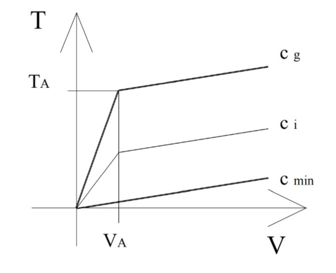
Vibration simulations for a medium-sized passenger car are considered here, the model of which was mentioned in Section 3. The following parameter values regarding this vehicle have been adopted: m = 1250   kg —mass of the vehicle body; m 0 = 25   kg —reduced mass of the wheel and suspension elements; J x = m ρ x 2 ,   ρ x = 0.6   m —moment of the body inertia relative to the longitudinal axis; J y = m ρ y 2 ,   ρ y = 1.15   m —of the body inertia relative to the transverse axis; a 1 = 1.4   m ,   a 2 = 1.45   m ,   b 1 = b 2 = 0.725   m —measurements defining location of the body mass center relative to the wheels; h s = 0.5   m —height of the vehicle mass center above the road surface (Figure 8); k 1 = k 2 = 14.5   kN / m —rigidity of front and rear wheel springs; k 0 = 200   kN / m —stiffness of the wheel tire; c 0 = 2.5 · 10 5   Ns / m —coefficient of tire damping; κ 1 = κ 2 = 1.5 · 10 3   Ns / rad —rigidity of front and rear stabilizers. The vehicle considered is equipped with the magneto-rheological dampers (MR dampers) whose characteristic is shown in Figure 6. The following parameters were adopted, shown in the Figure 10: T A = 400   N , V A = 0.0075   m / s , c min = 210   Ns / m , c g = 3 · c min , I max = 2   A .
In the MR damper, the parametric variable represents the current flowing through the winding of the coil located at the damper’s side [11,31]. On the basis of the presented data, the damper characteristics have been formulated (1) as follows:
f V ; τ = c min V + f max V c min τ ,
if
f max V = T A V A V gdy V V A T A + c g V V A signV gdy V > V A ,
τ = I I max ,   I 0 , I max   τ R 1 ,
where   I —intensity of the current flowing through the coil winding.
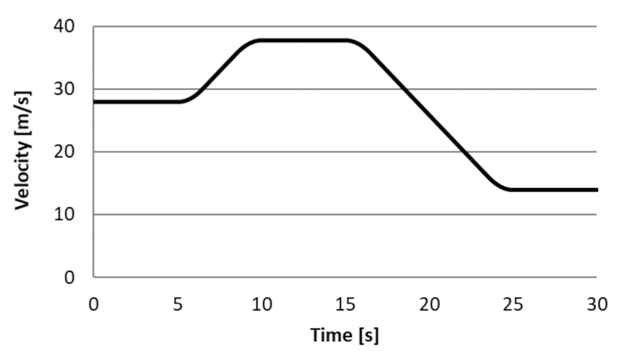
Moreover, the assumption was made that the vehicle moves along the road, the roughness of which is described by the following function: ξ s = ξ 0 sin 2 π S L , where ξ 0 = 5   mm , L = 12   m , s —the stretch of road covered. The vehicle is moving at variable velocity, the plot of which is shown in Figure 11. Another assumption was that the road’s uneven surface under the left-side and right-side wheels is not exactly the same but shifted in phase by · s = a 1 . In the presented paper, harmonic excitation was used. In this type of research, excitation based on the road profile in accordance with ISO 8608 [32,33] is often used.
The assumption was made that parameters of the virtual damper, included in Formula (40), are determined on the basis of non-dimensional damping coefficients amounting to γ z sky = 0.413 ;   γ φ x sky = 0.814 ; γ φ y sky = 0.470 . Due to the comparative character of the performed tests, it was assumed that the reference vehicle is equipped with classic shock absorbers (dampers) whose bi-directional characteristic is determined by two constants: c 1 = 500   Ns / m when the shock absorber is squeezed, and c 2 = 2.5 · c 1 when the shock absorber is stretched.
While using the presented model, the vehicle motion on the described road was simulated with the velocity given in Figure 11, and the drive time amounted to 30   s . It was assumed that at the initial moment (t = 0), all coordinates and corresponding velocities (see: Equations (11–14)) were equal to zero.
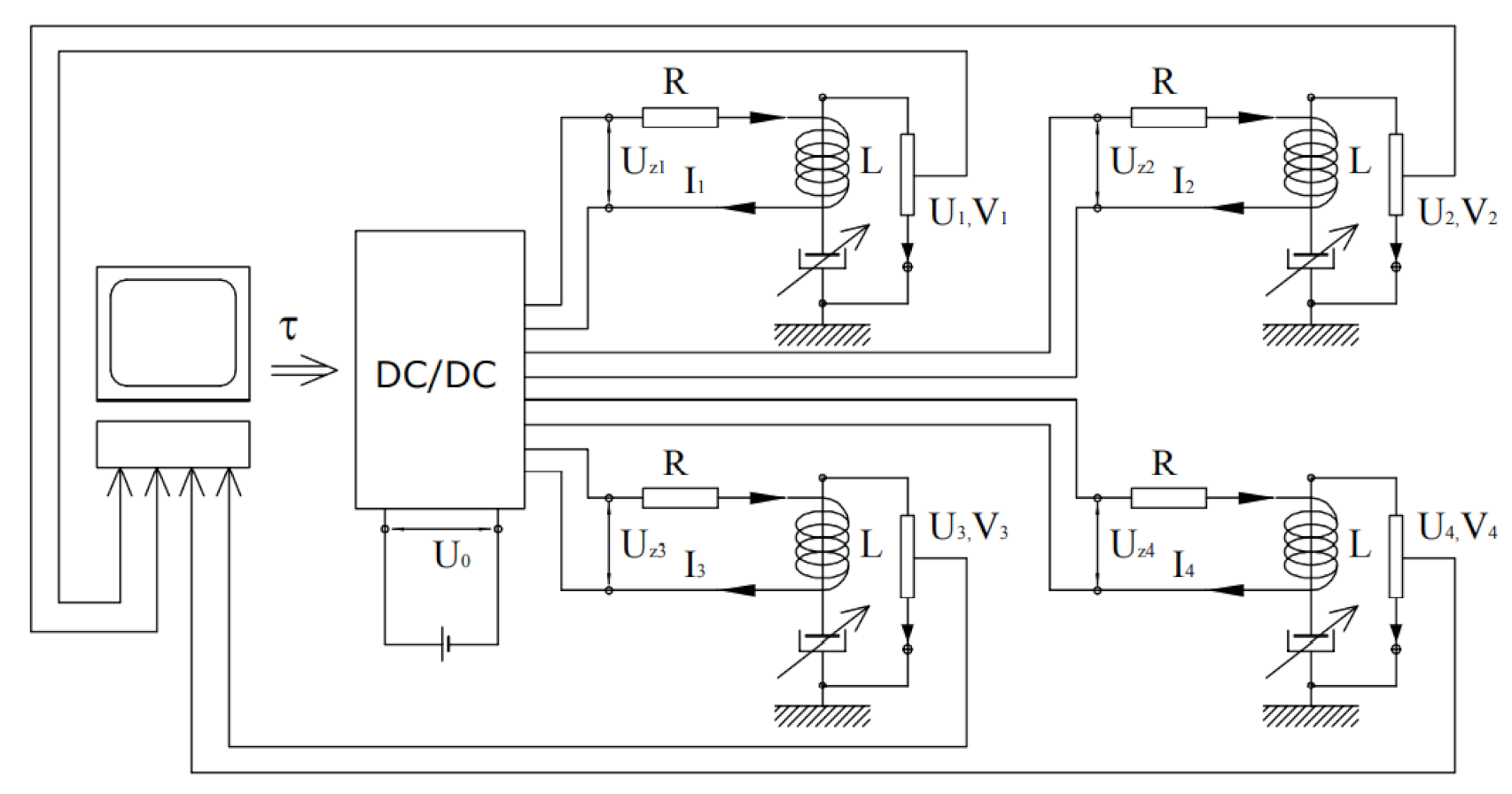
Figure 12 shows a scheme of the supply system for the MR damper coil, i.e., of the system featuring the parametric variable τ , which is the current flowing through the coil.
The waveforms for the currents I I ,   i = 1 , , 4 flowing through coils in the dampers, determined according to the system of equations. The following parameter values of the coil supply systems were adopted R = 2   Ω ,   L = 6   mH ,   I max = 2   A .
L I ˙ i + RI i = RI i opt ,
where I i opt is computed on the basis of the damper characteristic described by Formulas (66–68):
I i opt = f 1 V i ,   T i opt ,   i = 1 , , 4 ,
To evaluate the body vibrations, an indicator was adopted whose values determine the sum of the acceleration squares in the four points of the body above the wheels (Figure 6):
W 1 = 0 t end i = 1 4 a i 2 t dt 1 2 ,
where a i —accelerations of the enumerated points, i = 1 , , 4 .
Additionally, the value of an indicator characterizing change in the wheels’ pressure on the road surface was also determined:
W 2 = 0 t end i = 1 4 N i 2 t dt 2 ,
if
N i t = ( S 0 i t + T 0 i t ) 1 Q 0 i ,   i = 1 , ,   4 ,
where forces are described by Formula (16), and Q 0 i —static wheel pressure.
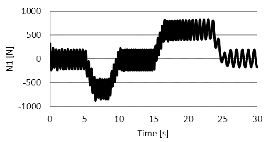
Three vibration simulations were conducted for the vehicle moving under the conditions described above. During the first simulation, the vehicle was equipped with classic dampers whose characteristic is given earlier in point 4. The Figure 13 shows the change in the wheels’ pressure on the road surface on the front axle, and Figure 14 shows the change in vertical accelerations over the front axle.
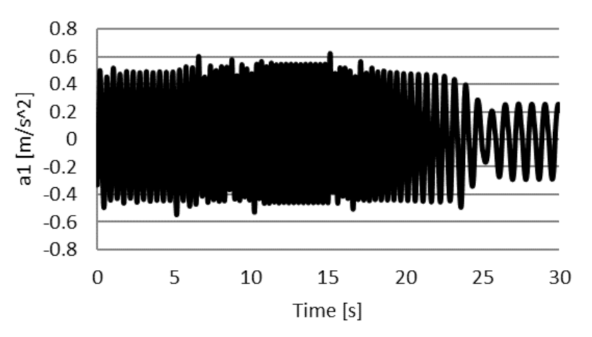
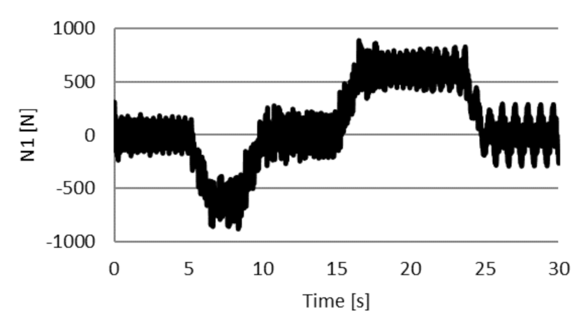
The second simulation was conducted with regard to the vehicle equipped with the MR dampers whose characteristic is given in Figure 11; optimal values of forces in the dampers were determined in this simulation in accordance with the first criterial function K 1 . The changes in pressure on the road surface on the front axle is shown in Figure 15, and the vertical acceleration on the front axle is shown in Figure 16.
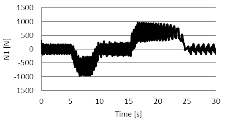
The third simulation was analogous to the second, but the forces in the dampers were determined in accordance with the first criterial function K sky . Figure 17 shows the change in the wheels’ pressure on the road surface on the front axle, and Figure 18 shows the change in vertical acceleration over the front axle.
The purpose of this simulation research was the effectiveness comparison of reduction in the vehicle vibration in the three situations described above. Evaluation of this effectiveness was performed based on indicators W 1 and W 2 , which characterize the intensity of the vibration. At the same time, the smaller the value of the indicator, the greater the efficiency of the vibration reduction. Table 1 presents the values of the considered indicators.
The results obtained show that the values of indicators W 1 —characterizing the vibration intensity with regard to comfort—are significantly smaller for a vehicle equipped with the MR dampers than for a vehicle with classic dampers. In the K 1 system, the W 1 indicator has shown an improvement of 51.6%, compared to the classic suspension, and in the K sky system, one of 42.5%.
However, the influence of the form of the criterial function used in the control system on the value W 1 is insignificant.
In the case of indicator W 2 —determining changes in the wheel vertical forces—the impact of the MR dampers controlled in accordance with the criterion K 1 , is little (4.9% reduction). However, as a result of the control according to the K sky   criterion, there was a 90.8% increase in the W 2 value, which indicates that the conditions of impact of the wheels on the road surface deteriorated.

6. Conclusions

This paper focuses on the optimization issue related to the semi-active system for damping the vehicle vibration. The problem was formulated and the method for determining the optimal values of the forces damping the vehicle vibration proposed. In the next step, two vibration simulations of the vehicle equipped with the semi-active vibration damping system were conducted. In the course of computations, there were optimal values of the four forces determined at all moments of time. Additionally, the simulation of the vibration of the vehicle equipped with the classic dampers was performed. On the basis of the simulation results, the values of the indicators used to evaluate the vibration intensity of a vehicle moving along the established route were determined. Analysis of these results showed that due to the use of the semi-active system for vibration damping, a substantial decrease in the body accelerations occurred, which contributes to improvement in ride comfort. In a vehicle with controlled MR dampers by the criterial function K 1 , the W1 indicator was improved by 51.6%, compared to the classic suspension, while maintaining a constant W2 dynamic load index.
The semi-active system of reduction did not, however, significantly affect the minimizing of the change in the wheel pressure on the road surface. The lack of this effect is—in the authors’ opinions—caused by the active inertia forces arising during the acceleration or braking of the vehicle. Such slow-changing vehicle loads cannot be reduced by the action of semi-active vibration dampers.
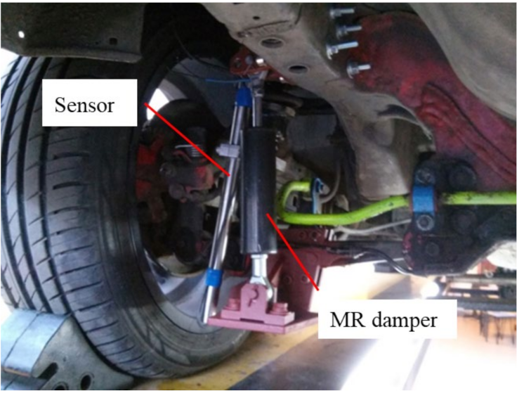
The work presented in the article was carried out to develop a determining algorithm for the damper control signal that will be applied to the semi-active vehicle’s vibration damping systems. Further testing will be performed, using a Honda del Sol vehicle equipped with a controlled magnetorheological damper. Figure 19 shows the suspension of the vehicle where the controlled MR dampers and the displacement sensors have been mounted to measure the suspension deflection.
Further simulation studies of a vehicle model with controlled MR dampers are planned. This paper presents studies where the vehicle vibrations were excited by a harmonic function. In order to relate the simulation results to road conditions, tests with random function excitation will be conducted [32,33].
In some vehicles moving at high speeds, there are special aerodynamic air deflectors (spoilers) generating forces that push the wheels against the road surface [34]. As a result, wheel slippage is prevented, which was mentioned in the introduction section of this paper. In their oncoming works, the authors plan to develop a model of the vehicle equipped with controlled aerodynamic plates for the purpose of reducing changes in vertical forces acting on the wheels during transient movement, which would create greater driving safety.

Author Contributions

W.G. contributed mathematical model of the control system; M.M. contributed mathematical model of the vehicles and identified numerical model parameters. W.G. and M.M. were performed the numerical experiments and analyzed data and involved into writing the article. Both authors have read and agreed to the published version of the manuscript.

Funding

This project was funded by the National Center for Research and Development as part of the PBS3/B6/34/2015.

Institutional Review Board Statement

Not applicable.

Informed Consent Statement

Informed consent was obtained from all subjects involved in the study.

Data Availability Statement

The data presented in this study are available on request from the corresponding author.

Conflicts of Interest

The authors declare no conflict of interest.

References

  1. Batterbee, D.C.; Sims, N.D. Hardware in the loop simulation (HILS) of magnetorheological damper for vehicle suspension systems. The University of Sheffield. J. Syst. Control Eng. 2007, 221, 265–278. [Google Scholar]
  2. Heidarian, A.; Wang, X. Review on Seat Suspension System Technology Development. Appl. Sci. 2019, 9, 2834. [Google Scholar] [CrossRef] [Green Version]
  3. Nam, Y.-J.; Park, M.-K. Electromagnetic Design of a Magnetorheological Damper. J. Intell. Mater. Syst. Struct. 2009, 20, 181–191. [Google Scholar] [CrossRef]
  4. Sapiński, B. Theoretical analysis of magnetorheological damper characteristics in squeeze mode. Acta Mech. Autom. 2015, 9, 89–92. [Google Scholar] [CrossRef] [Green Version]
  5. Choi, S.B.; Choi, Y.T.; Chang, E.G.; Han, S.J.; Kim, C.S. Control characteristics of a continuously variable ER damper. Mechatronics 1998, 8, 143–161. [Google Scholar] [CrossRef]
  6. Vivas-Lopez, C.A.; Hernández-Alcantara, D.; Morales-Menendez, R.; Ramírez-Mendoza, R.A.; Ahuett-Garzsa, H. Method for modeling electrorheological dampers using its dynamic characteristics. Math. Probl. Eng. 2015, 2015. [Google Scholar] [CrossRef]
  7. Bartkowski, P.; Zalewski, R.; Chodkiewicz, P. Parameter identification of Bouc-Wen model for vacuum packed particles based on genetic algorithm. Arch. Civ. Mech. Eng. 2019, 19, 322–333. [Google Scholar] [CrossRef]
  8. Carlson, J.D.; Matthis, W.; Toscano, J.R. Smart prosthetics based on magnetorheological fluids. Smart Struct. Mater. Ind. Commer. Appl. Smart Struct. Technol. 2001, 4332, 308–317. [Google Scholar]
  9. Choi, S.-B.; Nam, M.-H.; Lee, B.-K. Vibration control of a MR seat damper for commercial vehicles. J. Intell. Mater. Syst. Struct. 2000, 11, 936–944. [Google Scholar] [CrossRef]
  10. Kim, K.; Jeon, D. Vibration suppression in an MR fluid damper suspension system. J. Intell. Mater. Syst. Struct. 1999, 10, 779–786. [Google Scholar] [CrossRef]
  11. Makowski, M. Algorithm for Damping Control in Vehicle Suspension Equipped with Magneto-Rheological Dampers. In Dynamical Systems in Theoretical Perspective. DSTA 2017; Springer Proceedings in Mathematics & Statistics; Awrejcewicz, J., Ed.; Springer: Cham, Switzerland, 2017; Volume 248, Print ISBN 978-3-319-96597-0; Online ISBN 978-3-319-96598-7. [Google Scholar] [CrossRef]
  12. Spencer, B.F.; Nagarajaiah, S. State of the art of structural control. J. Struct. Eng. 2003, 129, 845–856. [Google Scholar] [CrossRef]
  13. Jung, H.J.; Sodeyama, B.F.; Ni, Y.Q.; Lee, I.W. State-of-the-art of semiactive control systems using MR fluid dampers in civil engineering applications. Struct. Eng. Mech. 2004, 17, 493–526. [Google Scholar] [CrossRef]
  14. Liu, Y.F.; Lin, T.K.; Chang, K.C. Analytical and experimental studies on building mass damper system with semi-active control device. Inter. J. Intell. Syst. 2018. [Google Scholar] [CrossRef]
  15. Bui, Q.-D.; Nguyen, Q.H.; Nguyen, T.T.; Mai, D.-D. Development of a Magnetorheological Damper with Self-Powered Ability for Washing Machines. Appl. Sci. 2020, 10, 4099. [Google Scholar] [CrossRef]
  16. Spelta, C.; Previdi, F.; Savaresi, S.M.; Fraternale, G.; Gaudiano, N. Control of magnetorheological dampers for vibration reduction in a washing machine. Mechatronics 2009, 19, 410–421. [Google Scholar] [CrossRef]
  17. Fu, B.; Giossi, R.L.; Persson, R.; Stichel, S.; Bruni, S.; Goodall, R. Active suspension in railway vehicles: A literature survey. Rail. Eng. Sci. 2020, 28, 3–35. [Google Scholar] [CrossRef] [Green Version]
  18. Wang, D.H.; Liao, W.H. Semi-active suspension systems for railway vehicles using magnetorheological dampers. Veh. Syst. Dyn. 2009, 47, 1305–1325. [Google Scholar] [CrossRef]
  19. Phu, D.X.; An, J.-H.; Choi, S.-B. A Novel Adaptive PID Controller with Application to Vibration Control of a Semi-Active Vehicle Seat Suspension. Appl. Sci. 2017, 7, 1055. [Google Scholar] [CrossRef]
  20. Warczek, J.; Burdzik, R.; Konieczny, Ł. The Concept of Autonomous Damper in Vehicle Suspension. In Dynamical Systems in Applications. DSTA 2017; Springer Proceedings in Mathematics & Statistics; Awrejcewicz, J., Ed.; Springer: Cham, Switzerland, 2017; Volume 249. [Google Scholar]
  21. Yoon, D.S.; Kim, D.S.; Choi, S.B. Response time of magnetorheological dampers to current inputs in a semi-active suspension system: Modeling, control and sensitivity analysis. Mech. Syst. Signal Process. 2021, 146, 106999. [Google Scholar] [CrossRef]
  22. Sands, T. Optimization Provenance of Whiplash Compensation for Flexible Space Robotics. Aerospace 2019, 6, 93. [Google Scholar] [CrossRef] [Green Version]
  23. Shuilong, H.; Chen, K.; Enyong, X.; Wei, W.; Zhansi, J. Commercial Vehicle Ride Comfort Optimization Based on Intelligent Algorithms and Nonlinear Damping. Hindawi Shock Vib. 2019, 2019. [Google Scholar] [CrossRef]
  24. Faraj, R.; Graczykowski, C. Hybrid Prediction Control for self-adaptive fluid-based shock-absorbers. J. Sound Vib. 2019, 449, 427–446. [Google Scholar] [CrossRef]
  25. Yan, G.; Sun, B.; Lü, Y. Semi-active model predictive control for 3rd generation benchmark problem using smart dampers. Earthq. Engin. Engin. Vib. 2007, 6, 307–315. [Google Scholar] [CrossRef]
  26. Karnopp, D.C.; Crosby, M.J. Vibration Control Semi-Active Force Generators. Asmej Eng. Ind. 1974, 96, 619–626. [Google Scholar] [CrossRef]
  27. Karnopp, D.C. Active damping in road vehicle suspension system. Veh. Syst. Dyn. 1983, 12, 183–188. [Google Scholar] [CrossRef]
  28. Bouc, R.A. Mathematical Model for Hysteresis. Acta Acust. United Acust. 1971, 24, 16–25. [Google Scholar]
  29. Dyke, S.J.; Spencer, B.F., Jr.; Sain, M.K.; Carlson, J.D. Modeling and control of magnetorheological dampers for seismic response reduction. Smart Mater. Struct. 1996, 5, 565. [Google Scholar] [CrossRef]
  30. Peng, Y.; Yang, J.; Li, J. Parameter identification of modified Bouc–Wen model and analysis of size effect of magnetorheological dampers. J. Intell. Mater. Syst. Struct. 2018, 29, 1464–1480. [Google Scholar] [CrossRef]
  31. Makowski, M.; Knap, L. Investigation of an off-road vehicle equipped with magnetorheological dampers. Adv. Mech. Eng. 2018, 10, 1–11. [Google Scholar] [CrossRef]
  32. Múčka, P. Simulated road profiles according to ISO 8608 in vibration analysis. J. Test. Eval. 2018, 46, 405–418. [Google Scholar] [CrossRef]
  33. Lenkutis, T.; Cerškus, A.; Šešok, N.; Dzedzickis, A.; Bucinskas, V. Road Surface Profile Synthesis, Assessment of Suitability for Simulation. Symmetry 2021, 13, 68. [Google Scholar] [CrossRef]
  34. Schütz, T. Hucho-Aerodynamik des Automobils, ATZ/MTZ-Fachbuch; Springer Fachmedien: Wiesbaden, Germany, 2013. [Google Scholar]
Figure 1. Diagram of the magnetorheological MR-IP damper: 1—coil, 2—orifices, 3—magnetorheological fluid, 4—housing, 5—magnetic field, 6—piston, 7—piston rod.
Applsci 11 04577 g001
Figure 2. Dissipative characteristic of the MR-IP damper, (a) plane: force–displacement, (b) plane: force–velocity.
Applsci 11 04577 g002
Figure 3. Rheological model of the MR damper; T 0 , c 0 , c 1 , k —model parameters, x , y —coordinates of the model.
Applsci 11 04577 g003
Figure 4. Results of numerical research on the MR damper model, (a) plane: force–displacement, (b) plane: force–velocity.
Applsci 11 04577 g004
Figure 5. Comparison of results experimental and numerical research the MR damper with 2A current, (a) plane: force–displacement, (b) plane: force–velocity.
Applsci 11 04577 g005
Figure 6. Schematic plot of dissipative characteristic of the semi-active damper T = f v ; τ ; T —friction force, v —velocity of damper deformation, τ —damping parameter.
Applsci 11 04577 g006
Figure 7. Scheme of the mechanical system adopted as a vehicle model; S—center of mass; Z—displacement of the bodywork in the Z direction; Φx—rotation about the X-axis; Φy—rotation about the Y-axis; m—mass of the body; Jx—moment of inertia about the X-axis; Jy—moment of inertia about the Y-axis; T1, T2, T3, T4—friction forces in suspension; k1, k2, k3, k4—spring coefficients in suspension; m0—mass of wheel; z01, z02, z03, z04—displacement of the wheels in the Z direction; k0—spring coefficients in wheel; c0—damping coefficients in wheel; ξ 1 ,   ξ 2 ,   ξ 3 ,   ξ 4 kinematic excitations; Vvehicle—vehicle velocity; a1, a2, b1, b2—position of the suspension in relation to the center of mass; 1, 2, 3, 4—acceleration measurement points.
Applsci 11 04577 g007
Figure 8. Scheme of the mechanical system adopted as a vehicle model—sky hook; Z—displacement of the bodywork in the Z direction; Φx—rotation about the X axis; Φy—rotation about the Y axis; cz—damping coefficient relative to the sky in the Z direction; cx—angular damping coefficient relative to the sky in about the X axis; cy—angular damping coefficient relative to the sky in about the Y axis; T1, T2, T3, T4—friction forces in suspension; k1, k2, k3, k4—spring coefficients in suspension; m0—mass of wheel; z01, z02, z03, z04—displacement of the wheels in the Z direction; k0—spring coefficients in wheel; c0—damping coefficients in wheel; ξ 1 ,   ξ 2 ,   ξ 3 ,   ξ 4 kinematic excitations; Vvehicle—vehicle velocity.
Applsci 11 04577 g008
Figure 9. Schematic plot illustrating relationship (50) where T T min ,   T max , λi—i-th parameter of the optimization vector, Ti—i-th friction force, Tmin—minimum value of the friction force, Tmax—maximum value of the friction force.
Applsci 11 04577 g009
Figure 10. Adopted characteristic of the MR damper, T —friction force, v —velocity of damper deformation, cmin—minimum value of the damping coefficient, cg—maximum value of the damping coefficient, ci—i-th value of the damping coefficient, TA—value of the friction force at point A, VA—value of the velocity of damper deformation at point A.
Applsci 11 04577 g010
Figure 11. Present waveform of vehicle velocity.
Applsci 11 04577 g011
Figure 12. Scheme of the supply system: τ —control signal (vector of damping parameter); U0—battery voltage; Uz1, Uz2, Uz3, Uz4—coil supply voltage; I1, I2, I3, I4—coil current; R—resistance; L—coil inductance; U1, U2, U3, U4—displacement of the dampers; V1, V2, V3, V4—velocity of the dampers.
Applsci 11 04577 g012
Figure 13. Change in the wheels’ pressure on the road surface on the front axle without control.
Applsci 11 04577 g013
Figure 14. The change in vertical accelerations over the front axle without control.
Applsci 11 04577 g014
Figure 15. Change in the wheels’ pressure on the road surface on the front axle with control by criterial function K 1 .
Applsci 11 04577 g015
Figure 16. The change in vertical acceleration over the front axle with control by criterial function K 1 .
Applsci 11 04577 g016
Figure 17. Change in the wheels’ pressure on the road surface on the front axle with control by criterial function K sky .
Applsci 11 04577 g017
Figure 18. The change in vertical accelerations over the front axle with control by criterial function K sky .
Applsci 11 04577 g018
Figure 19. Vehicle with controlled MR damper.
Applsci 11 04577 g019
Table 1. Indicator values.
Criterion K 1 K s k y Classic K 1 / C   [ % ] K s k y / C   [ % ]
W12.23622.65684.621251.642.5
W20.32500.65230.34184.9−90.8
Publisher’s Note: MDPI stays neutral with regard to jurisdictional claims in published maps and institutional affiliations.