Article

Backstepping Control of an Unmanned Helicopter Subjected to External Disturbance and Model Uncertainty

1
School of Aeronautic Science and Engineering, Beihang University, Beijing 100191, China
2
Zhito Technology Co., Ltd., Shanghai 200082, China
*
Author to whom correspondence should be addressed.
Appl. Sci. 2021, 11(12), 5331; https://doi.org/10.3390/app11125331
Submission received: 6 May 2021 / Revised: 3 June 2021 / Accepted: 7 June 2021 / Published: 8 June 2021
(This article belongs to the Section Robotics and Automation)

Abstract

:
A helicopter is a highly nonlinear system. Its mathematical model is difficult to establish accurately, especially the complicated flapping dynamics. In addition, the forces and moments exerted on the fuselage are very vulnerable to external disturbances like wind gust when flying in the outdoor environment. This paper proposes a composite control scheme which consists of a nonlinear backstepping controller and an extended state observer (ESO) to handle the above problems. The stability of the closed-loop system can be guaranteed based on Lyapunov theory. The external disturbances and model nonlinearities are treated as a lumped disturbance. Meanwhile, the ESO is employed to compensate the influence by estimating the lumped disturbance in real-time. Numerical simulation results are presented to demonstrate that the algorithm can achieve accurate and agile attitude tracking under the external wind gust disturbances even with model uncertainties. When coming to the flight test, a block dropping device was designed to generate a quantifiable and replicable disturbance, and the experimental results indicate that the algorithm introduced above can reject the external disturbance rapidly and track the given attitude command precisely.

1. Introduction

Due to its capability of vertically taking-off and landing, hovering and flying at low altitude, unmanned helicopters have a variety of applications in both military and civilian areas, such as search and rescue, surveillance and communication relay. However, it is a challenging mission to design an appropriate controller for an autonomous helicopter as its mathematical model consists of high nonlinearity and parameter uncertainties. When coming to the outdoor flight environment, the helicopter is easily influenced by the external disturbances like wind gust. Therefore, precise tracking of aggressive command in adverse environments has become one of the prevailing research topics for autonomous helicopters.
In recent years, a lot of research has been undertaken to realize autonomous flight of unmanned aerial vehicles (UAVs). Different kinds of control algorithms have been applied in the flight control system. Linear control methods were very popular in the early days. The PID algorithm based on the H-infinity theory was used to control a quadrotor helicopter [1]. In [2], the Linear Quadratic Regulator (LQR) was designed for the trajectory tracking of a quadrotor based on linear model. H-infinity control was presented to enhance an UAV’s capability of rejecting wind disturbances when hovering [3], and in [4], system uncertainties and nonlinear dynamics were considered in the design of attitude controller using H-infinity control strategy, and the simulation results showed that the control system worked well. However, linear control methods could not satisfy the full flight envelope. When the UAV is maneuvering or flying in adverse environments, the above methods designed based on a linear model would not be effective. Therefore, nonlinear control methods and intelligent control algorithms have been developed to solve these problems.
Feedback linearization is usually applied as a state feedback to make the nonlinear system linear. After the system is linearized, it is much more convenient to design the control system with linear control algorithms. In [5], feedback linearization was used to decouple the nonlinear system of an unmanned helicopter and a sliding-mode observer was employed to estimate the external disturbances. To deal with the mismatched disturbances, feedback linearization and a novel sliding-mode control were proposed for the helicopters to enhance the robustness of system [6].
Adaptive control is widely utilized for dealing with external disturbance and parameter uncertainties. It is more like a strategy than an algorithm, which has a variety of forms to improve the adaption of system. In [7], an adaptive law is presented to deal with the model uncertainties using a neural network, and it allowed the authors to design the controller of unmanned helicopters based on a simplified model. In [8], the researchers developed an adaptive update law to estimate the unknown disturbances exerted on the forces and moments, which improved the capabilities of disturbance rejection in both inner and outer loops. In [9], a L1 adaptive law is chosen to assist the controller to obtain better robustness against disturbances and uncertainties, and they were conducted on a multirotor to achieve attitude control.
Sliding mode control (SMC) aims to make the system work on the sliding mode surface whether the system is under external disturbance or model parameter variation. Different reaching laws are studied to improve the performance of dynamic response. In [10], a novel sliding mode surface was proposed to handle the mismatched external disturbances, and the controller designed based on it showed better hovering performance when the unmanned helicopter was under the mismatched disturbances. To eliminate the perturbations, the researchers proposed an integral SMC and chose a proper sliding surface to achieve trajectory tracking for an unmanned helicopter [11]. Additionally, in [12], a composite control strategy which consists of a continuous terminal SMC and a disturbance observer was carried out to stabilize the attitude of the unmanned helicopter and land it on the shipboard.
Model predictive control (MPC) is a control method capable of dealing with both linear and nonlinear problems, in addition to UAVs, it is also widely applied to solve the optimization problem of automatic driving. By considering the constraints on both state variables and control inputs, MPC could achieve good tracking performance under given conditions [13]. In [14], the explicit nonlinear MPC was used to build the multi-time-scale control structure, while a state observer was designed to handle disturbances and the dynamic inversion was employed to simplify the input–output relations, these algorithms were tested on a mode-scale helicopter. To deal with model uncertainties, an MPC strategy based on an adaptive law was proposed for an unmanned helicopter with two degrees of freedom in [15]. In addition to the unmanned helicopter, there were also other kinds of UAV using MPC-based control method to achieve autonomous flight, such as VTOL UAV [16] and ducted fan aircraft [17].
With the development of artificial intelligence (AI) technology, intelligent control has gained a lot of attention in the field of robot control. In the past decade, various intelligent control methods have been developed for UAV to achieve better performance of flight, for example, fuzzy-logic control [18], neural network [19] and reinforcement learning [20].
Although the utility of control methods mentioned above has made a great success in dealing with control design, the problem of handling nonlinearities, especially the flapping dynamics, external disturbances and model uncertainties together still needs further research. Feedback linearization could not deal with external disturbances, and if the model is not accurate enough, the effect will be greatly reduced. Adaptive control could not handle nonlinearity. The SMC easily generates a serious chattering phenomenon, which will cause damage to the actuators. The optimization process of MPC always needs powerful computing capabilities, which could not be satisfied in normal flight control computers. Additionally, an accurate model is also necessary to achieve good control performance. Intelligent control is usually combined with other methods, and there exists a lot of calculating. According to the above introduction, it is impossible to solve those problems simultaneously using a single control algorithm, and most researchers have been working on compound control strategies.
Backstepping is one of the most widely used control methods. Due to helicopters’ multivariable and underactuated characteristics, backstepping is suitable to build a cascaded control structure by introducing virtual inputs. As it is usually designed based on Lyapunov theory, the stability of the system could always be guaranteed. Due to these advantages, it has attracted great interest in recent years, some valuable research results have already been presented to improve the system robustness and stability [21,22,23,24]. In [21], a novel sensor-based backstepping technique was developed to enhance the robustness of the UAV control system. Additionally, in [22], a proportional integral (PI) observer was proposed to deal with the disturbances, and the backstepping control combined with the observer were applied to achieve trajectory tracking. In [23,24], backstepping method was used to cooperate with fast terminal SMC to realize position and attitude tracking for a quadcopter. However, model uncertainty and external disturbance could not be handled well only based on the backstepping method, thus, researchers have come up with various forms of observers to estimate them without having specific information [25,26,27]. In [25], a disturbance observer only considering hovering state was designed to compensate for environmental disturbance. In [26,27], a nonlinear disturbance observer was designed to estimate external disturbances. In addition to these observers mentioned above, the most famous one is extended state observer (ESO) [28], but almost none of them have been tested in real flight conditions.
In this work, a Backstepping Active Disturbance Rejection Controller (Backstepping -ADRC) hybrid is proposed to achieve attitude tracking for an autonomous helicopter under the influence of environmental disturbances and nonlinear aerodynamic forces. The forces from external disturbances and internal nonlinear model are treated together as total disturbances. An ESO and a backstepping controller are designed to estimate and compensate for the total disturbances without reliance on a precise system model to eliminate their effects simultaneously and achieve precise attitude tracking. As disturbance and nonlinearity rejection are separated from attitude tracking control, the performance and robustness could be guaranteed independently without compromise. The utility of the proposed controller was validated through simulations and flight tests and compared with a PID controller.
The rest of the article is organized as follows. Section 2 presents the related work of this paper. The mathematical model of helicopter and wind gust are presented in Section 3. In Section 4, firstly, the ESO is designed to estimate total disturbances mainly including flapping dynamics and wind gust in this paper, secondly, the procedure of backstepping controller design is presented, at last, considering parameter uncertainties. Then, simulation results and flight tests are shown in Section 5 and Section 6, respectively. The conclusions of the paper are described in Section 7.

2. Related Work

Nonlinearity, model uncertainty and external disturbance have already become the key problems of UAV control systems. Development of single nonlinear control algorithm is generally able to handle one or two of them. However, hybrid control strategies could make full use of the advantages of each algorithm.
Single control method could also obtain good results, especially after optimization. In [29], a robust MPC algorithm was employed to deal with external disturbance, the effectiveness of the proposed method was proved by several flight experiments. A SMC technique was presented to estimate external disturbances and consider the nonlinearity of flapping dynamics, simulation results showed the control system designed based on a linearized model was effective [30]. The authors of [31] came up with an improved adaptive control algorithm for an unmanned helicopter in the presence of model uncertainties, and the hardware-in-loop simulations were designed for generating measurement noises and validating the control method. However, limited by the characteristics of single control method, it is difficult to meet distinct demands of all those problems mentioned above.
Hybrid control scheme is very popular in the design of flight control systems when facing multiple challenges. In [32], a neural network based observer was developed to estimate external disturbances and model uncertainties, while the control scheme of the UAV system was built with the backstepping control method, and only simulation results were provided in this paper. SMC combined with a nonlinear disturbance observer were studied to improve the tracking performance while the quadcopter was under disturbances and subjected to model uncertainties, simulation results were presented to demonstrate the effectiveness of the controller [33]. In [34], three categories were utilized to achieve the trajectory tracking of a small-scale helicopter, the first one was the linearization of the mathematical model by applying the feedback linearization technology, then, a disturbance observer was presented to estimate the total disturbances, which included matched ones and mismatched ones, at last, H-infinity control method was proposed to design the controller based on the linear model. Although there have been various studies on this topic, there still exist some unresolved problems, for example, flapping dynamics are barely considered in the control system, and controllers designed based on multiple algorithms bring too many parameters, which are difficult to adjust in flight experiments.
Most of the strategies mentioned above were only verified by simulation tests. In this paper, the flapping dynamics of a helicopter are taken into account. Nonlinearities, model uncertainties and external disturbances are totally handled through the proposed Backstepping–ADRC. Additionally the control structure is not too complicated, which makes it a little easier to deploy in the embedded system than most other schemes. Moreover, the parameters of the control law are reasonable, which makes parameter adjustment much simpler in the flight test.

3. Model Description of Helicopter and Wind Gust

In this section, the helicopter dynamic model consisting of attitude dynamics and rotor flapping dynamics are presented. The Euler angle is adopted to describe the orientation of the helicopter. Several assumptions and simplifications are made before the model is built based on the first-principles approach.
  • The helicopter is treated as a rigid body.
  • The off-axis moment of inertia is neglected as they are usually very small.
  • The counteractive torque of the tail rotor is ignored because it is too small.
  • The drag forces of the fuselage are ignored for simplification.
  • The forces and moments of horizontal and vertical fin are ignored for simplification.

3.1. Helicopter Modeling

Based on the assumptions and simplifications mentioned above, the helicopter attitude dynamic model described in the fuselage-fixed reference frame is given in (1).
Θ ˙ = S 1 ( Θ ) ω J ω ˙ = ω × J ω + Q Q = Q A τ + Q B Q A = h t Q m T m h m 0 T m h m Q m l t 0 T m l m , Q B = 0 T m l m Q m
where Θ = ϕ , θ , ψ T are Euler angles and ω = p , q , r T is angular velocity vector, respectively. S 1 ( Θ ) is the transformation matrix from the angular velocities to Euler angles derivatives. J = d i a g ( I x x , I y y , I z z ) is a diagonal matrix of moments of inertia in fuselage-fixed reference frame with the inertia coupling terms neglected, and Q = L , M , N T are the lumped moments exerted on the helicopter. T m , Q m denote the main rotor thrust and counteractive torque; τ = [ T t , β 1 c , β 1 s ] T are the system inputs of the model, with T t being the tail rotor thrust and β 1 c / β 1 s being longitudinal/lateral Tip-Path-Plane flapping angles of the main rotor. h m , h t , l m and l t represent the horizontal and vertical distances from the center of the rotor hub to the center of gravity.
As the main rotor flapping dynamics is the main source of nonlinear forces, the flapping dynamics are introduced in the helicopter model. The most complete and accurate analytical equation of rotor flapping dynamics is expressed as below in (2) [35].
β ¨ 1 c w β ¨ 1 s w = Ω γ 8 2 2 γ 8 β ˙ 1 c w β ˙ 1 s w Ω 2 P 2 1 + γ K 1 μ 2 16 γ 8 ( 1 + μ 2 2 ) γ 8 ( 1 + μ 2 2 ) P 2 1 + 3 γ K 1 μ 2 16 β 1 c w β 1 s w + Ω 2 0 0 γ 8 ( 1 + μ 2 2 ) 0 γ μ 3 γ μ 4 0 γ 8 ( 1 + 3 μ 2 2 ) θ 0 θ t θ 1 c w θ 1 s w + Ω 2 γ 8 γ 8 2 0 1 Ω 1 Ω 0 p w q w p ˙ w q ˙ w + Ω 2 0 γ μ 4 λ
A more specific explanation of this formula can be found in [35]. In order to simplify the controller design and model complexity, only the first-order of this formula is used here in (3) [36].
B ˙ 1 w = K ω ω 12 w + K B B 1 w + K θ θ 1 w
where B 1 w = β 1 c w , β 1 s w T , ω 12 w = p w , q w T , θ 1 w = θ 1 c w , θ 1 s w T . θ 1 c w / θ 1 s w , θ 0 are the longitudinal/lateral cyclic pitch and collective pitch of the swash plate, which means the actual system inputs. The subscript _w denotes the states in the wind-hub frame [35]. A detailed explanation of the parameter matrices K ω , K B and K θ is provided in [36]. Due to the fact that the flapping angles are much smaller than the collective pitch, the effect of wind gust disturbances on the flapping dynamics could be simplified as ζ = γ Ω μ / 6 , 0 T , where μ denotes the advance ratio. Then the main rotor flapping dynamics described above could be rewritten in (4).
B ˙ 1 w = K ω ω 12 w + K B B 1 w + K θ θ 1 w + ζ θ 0
The state variables transferred from the fuselage frame to the wind-hub frame is obtained by multiplying the rotation function in (5), where β represents the sideslip angle.
x c w x s w = H ( β ) x c x s = cos ( β ) sin ( β ) sin ( β ) cos ( β ) x c x s
The relationship between the thrust of tail rotor and the collective pitch is given in (6) [37].
T t = ρ Ω t 2 R t 2 A t C T t / 2 , C T t = a σ θ t / 3 λ t / 2 / 2
where λ t = λ c t / 2 + λ c t / 2 2 + C T t / 2 , λ c t = v / ( Ω t R t ) , v denotes the lateral wind gust and θ t is the collective pitch of tail rotor. The more specific explanation is provided in [37].

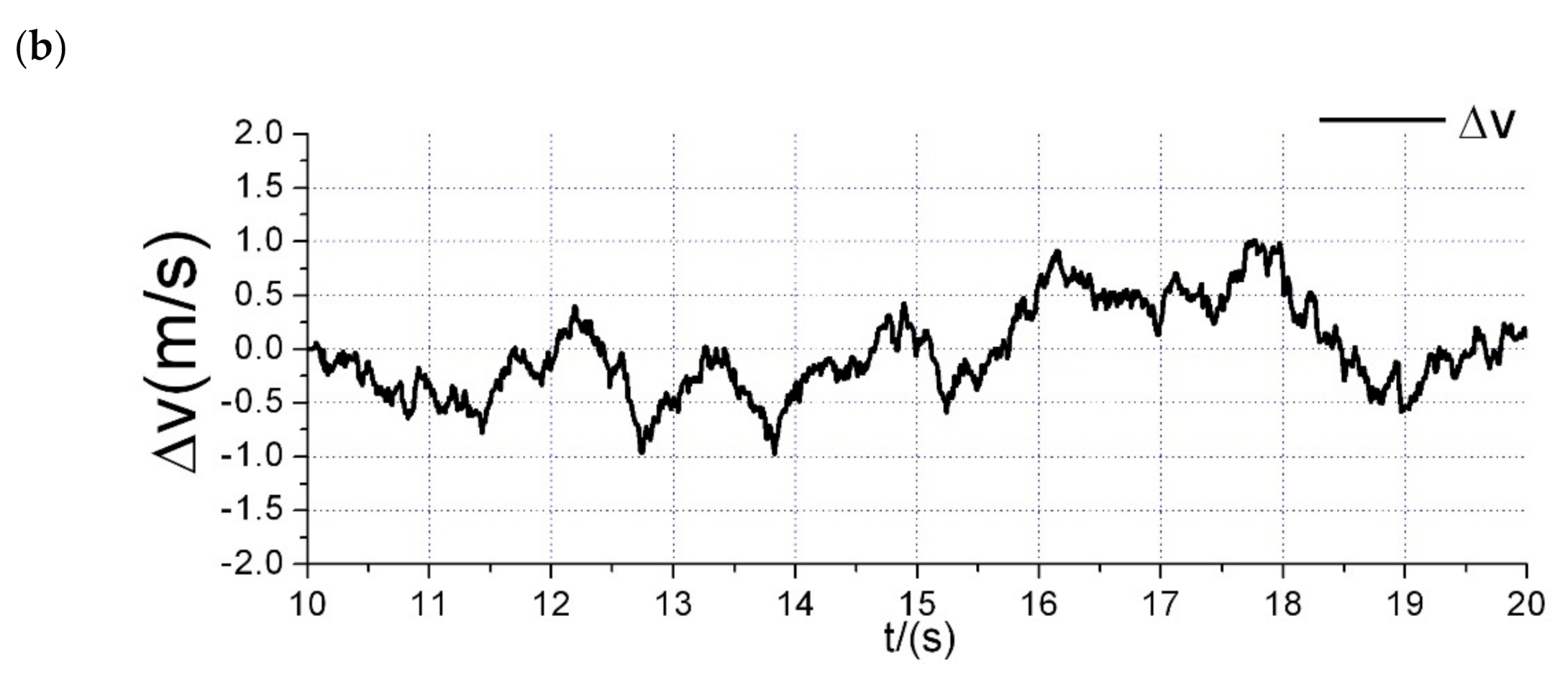
3.2. Mathematical Model of Wind Gust

Atmospheric turbulence usually has two kinds of models: Dryden and von Karman models [38]. In this paper, the Dryden spectral model of wind gust is adopted, and the framework is shown in (7).
H u ( s ) = Δ u W t = σ u 2 L u / π U 1 + ( L u / U ) s H v ( s ) = Δ v W t = σ v L v / π U 1 + ( 3 L v / U ) s ( 1 + ( L v / U ) s ) 2
With transfer functions H u ( s ) and H v ( s ) , the white noise W t can be generated by the speed increments Δ u / Δ v in the longitudinal direction and lateral direction, where U represents the speed of the helicopter. ( σ u , σ v ) are the turbulence intensities and ( L u , L v ) denote turbulence scale lengths; the calculation formulas are as follows:
L u = L v = h / ( 0.177 + 0.000823 h ) 1.2 σ u = σ v = 0.1 W 20 / ( 0.177 + 0.000823 h ) 0.4

4. Controller Design
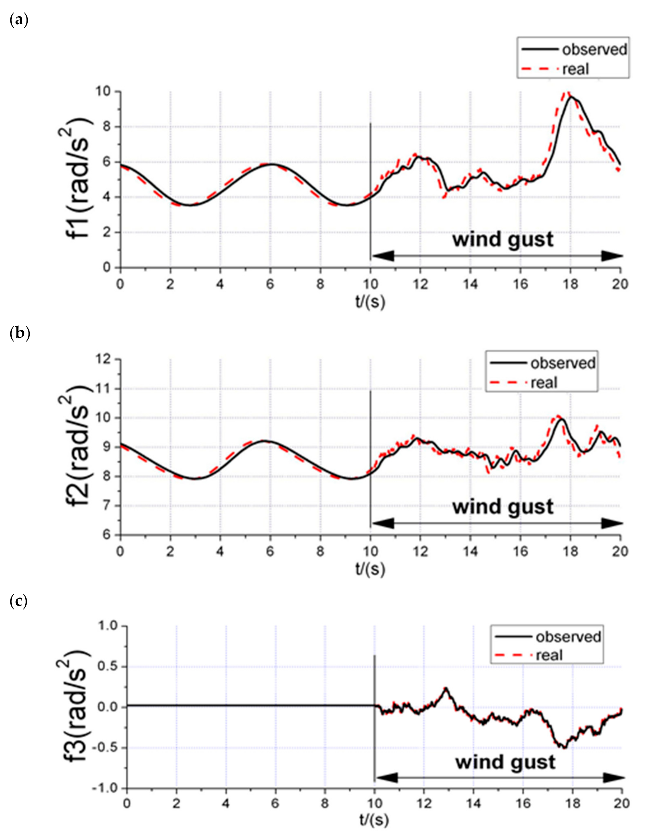
4.1. Design of ESO

Before the succeeding steps, model simplification and transformation should be performed to facilitate the model-based controller design. Due to the high rotation rate of the main rotor, the main rotor flapping dynamics are much faster than the fuselage attitude dynamics. Thus, the quasi-static assumption of flapping dynamics is made here [39], the Equation (4) could be simplified to (9).
B 1 w = K B 1 ( K ω ω 12 w + K θ θ 1 w + ζ θ 0 )
Then the helicopter model could be transformed to the simplified reference model in (10).
Θ ˙ = S 1 ( Θ ) ω ω ˙ = J 1 ( ω × J ω ) + Q ¯ Q ¯ = Q ¯ x , Q ¯ y , Q ¯ z T = f + R θ
Additionally, the variables mentioned above can be written specifically in (11).
f = f 1 , f 2 , f 3 T = f 12 T , f 3 T f 12 = f 1 , f 2 T = J 0 1 ( Q A 12 H 1 ( β ) K B 1 ( K ω H ( β ) ω 12 + ζ θ 0 ) + T t h t , T m l m T ) f 3 = ( ρ Ω t 2 R t 2 A t a σ λ t l t / 8 T m l m β 1 s Q m ) / I z z θ = θ 1 c , θ 1 s , θ t T = θ 1 T , θ t T R = R 12 0 0 0 0 R 3 R 12 = J 0 1 Q A 12 K B 1 K θ , R 3 = ρ Ω t 2 R t 2 A t a σ l t / 12 I z z Q A 12 = Q m T m h m T m h m Q m , J 0 = I x x 0 0 I y y
As nonlinearities and disturbances are assembled in one term, they can be compensated for by the controller with no difference. To acquire the disturbance information, which could not be measured directly by the sensor, an ESO is designed, where the structure is shown in (12).
z ˙ 1 = J 1 ( ω × J ω ) + z 2 + ( R 12 θ 1 ) T , R 3 θ t T B 01 e z ˙ 2 = B 02 f a l ( e , 0.5 , δ )
where z 1 = z p , z q , z r T , z 2 = z f 1 , z f 2 , z f 3 T , y = p , q , r T and e = e 1 , e 2 , e 3 T = z 1 y . B 0 x is the parameter matrix of the observer. f a l = f a l 1 , f a l 2 , f a l 3 T and f a l x are defined by (13).
f a l x ( e , a , δ ) = e x / δ a 1 e x δ e x a s i g n ( e x ) e x > δ
Due to the characteristics of nonlinear feedback and extended state, ESO could achieve accurate and agile observation of states and disturbances with little reliance on the system model [40]. Thus, it could be seen that the ESO presented above could track the total disturbances accurately as shown in (14).
z 1 y , z 2 f
Then, the observed total disturbances f could be treated as part of the model in the control system.

4.2. Backstepping Controller

After acquiring the total disturbance information, a backstepping recursive controller is designed for the reference model to achieve attitude tracking of a given attitude command, where the disturbance rejection is incorporated as an independent part.
As the first step of the backstepping controller design, let Lyapunov function candidate be
L 1 = Θ e T Θ e / 2
The subscript e represents the error between the real state and the given command, namely, x e = x x c .
Then the derivative is L ˙ 1 = Θ e T Θ ˙ e = Θ e T ( Θ ˙ Θ ˙ c ) = Θ e T ( S 1 ( Θ ) ω Θ ˙ c ) .
If ω = ω c = S ( Θ ) ( Θ ˙ c K 1 P Θ e ) , then
L ˙ 1 = Θ e T K 1 P Θ e 0
The next step is to select another Lyapunov function candidate
L 2 = L 1 + ω e T ω e / 2
Thus, L ˙ 2 = Θ e T K 1 P Θ e + Θ e T S 1 ( Θ ) ω e + ω e T ( ω ˙ ω ˙ c ) and ω ˙ = J 1 ( ω × J ω ) + Q ¯ .
Choose Q ¯ = Q ¯ c = J 1 ( ω × J ω ) + ω ˙ c ( S 1 ( Θ ) ) T Θ e K 2 P ω e , then
L ˙ 2 = Θ e T K 1 P Θ e ω e T K 2 P ω e 0
The last step is to calculate the θ * from Q ¯ = Q ¯ c and Q ¯ = f + R θ , these equations can be satisfied by choosing θ * = R 1 ( Q ¯ c f ) .
Where K 1 P and K 2 P are parameter matrices which are positive definite.
Finally, after all these steps, the control input θ * = θ 1 c * , θ 1 s * , θ t * is derived.

4.3. Analysis of Model Uncertainty

Although the model of helicopter is built, there exists errors in the model parameters. It has been proven that the ESO has significant robustness to the uncertainties of control input coefficients [40], which refer to R 12 and R 3 in this article. Therefore, only the inertia matrix J is necessary to be taken into account in this analysis.
Define J as the unknown inertia matrix with real parameters. Additionally, J ^ is defined as the one with uncertainties. Based on the theory presented in [40], the estimation results will be changed to (19) with the uncertain inertia matrix.
f ^ = f N N = J 1 ( ω × J ω ) J ^ 1 ( ω × J ^ ω )
The new pseudo-input of Q ¯ c will be obtained by subtracting an additional item N in (20).
Q ¯ ^ c = Q ¯ c N
When the new Q ¯ c and new f replace the old ones, new θ * will be obtained, and it is equal to the one derived without model uncertainty.
θ ^ = θ *
Even with the parameter uncertainties of inertia matrix, the actual control input is the same as the nominal one obtained above. Therefore, the system is robust to model uncertainties theoretically.

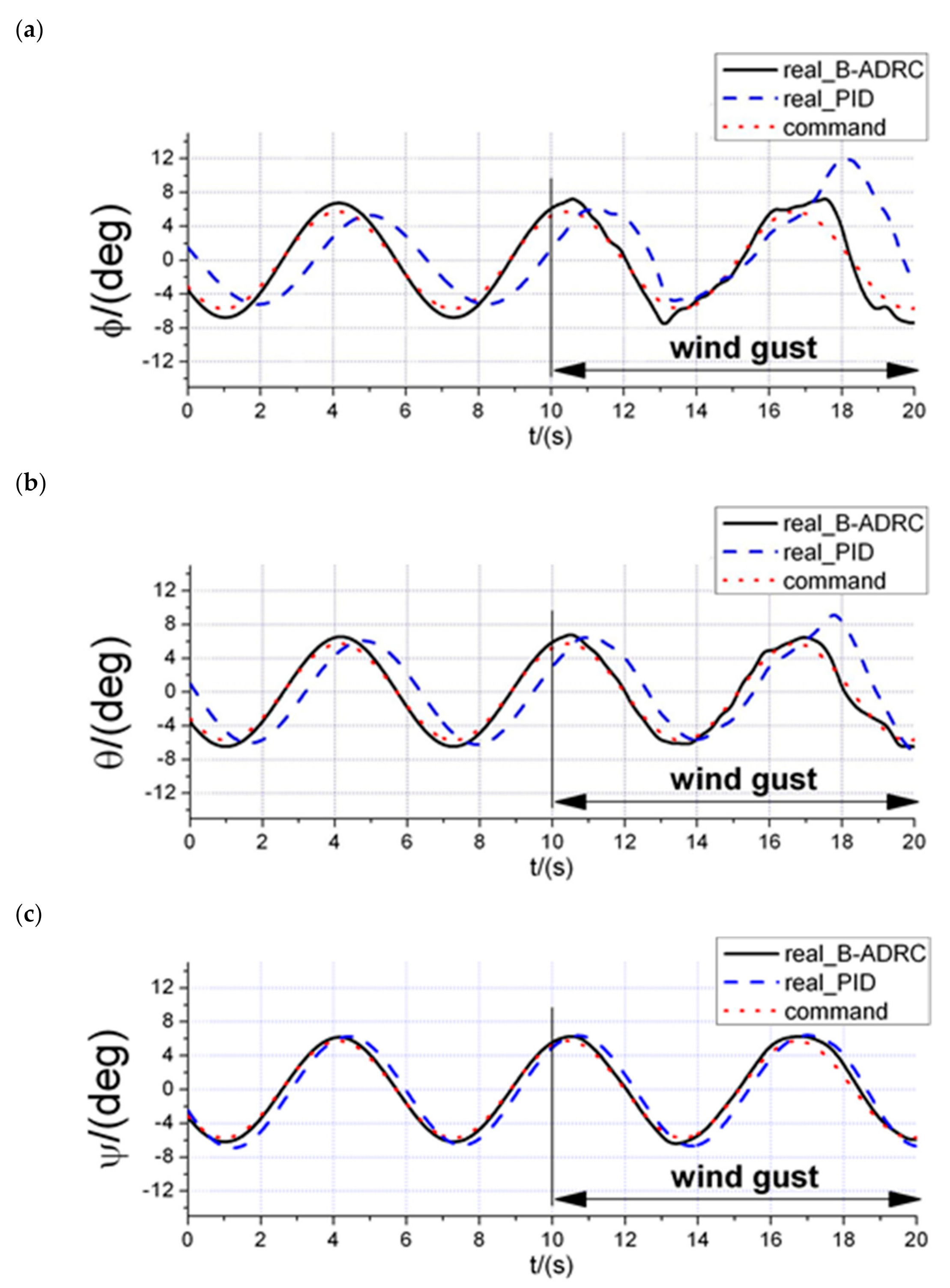
5. Simulation Results

The Backstepping-ADRC controller presented above was applied on the complete system model described in Section 3 in simulations. The proposed wind gust disturbances were exerted from t = 10 s, which is illustrated in Figure 1. The attitude command for the helicopter controlled by the proposed controller is ϕ c = θ c = ψ c = 5.73 × sin ( t + 10 ) . All simulation tests were carried out in the system described in Section 6.
A PID controller with high integral gain was also tested on the model under the same conditions because it is capable of rejecting disturbances due to its integral term. This allows for comparison with the Backstepping-ADRC. The main parameters of the model and controller are given in Table 1 and Table 2.
The simulation results are exhibited in Figure 2, Figure 3, Figure 4, Figure 5. Figure 2 presents the attitude tracking results of the proposed Backstepping-ADRC controller under the same conditions for comparison with the PID controller. Since the wind gusts were applied in the longitudinal and lateral directions, the pitch angle and roll angle should be emphasized. It is clear that the control method developed in this paper has better performance, as the tracking delay of the method is almost negligible, while the delay of PID control is nearly 1 s. Meanwhile, the amplitude of the tracking error is less than 3° when in the worst situation of the whole simulation progress, however, the PID’s reaches 10. For the roll angle, the average value of the tracking error is 0.65° for the Backstepping-ADRC controller, while it is 3.28° for PID controller. Additionally, the standard deviations of the tracking errors are 0.66° and 2.33°, respectively. For the pitch angle, the average value of the tracking error is 0.47° for the Backstepping-ADRC controller, while it is 2.14° for PID controller. Additionally, the standard deviations of the tracking errors are 0.38° and 1.65°, respectively.
The disturbance observation performance is illustrated in Figure 3. It is shown that the estimated value of the total disturbance is almost equal to the real one, and the delay is less than 0.2 s, which is totally acceptable. The system inputs generated by the controller are shown in Figure 4.
The simulation results shown above demonstrate that the proposed controller is capable of accurate and agile attitude tracking under external wind gust disturbances as well as nonlinear aerodynamic forces in forward flight. The total disturbances were successfully estimated by the rapid and precise estimation of ESO.
When compared to the PID controller, the attitude tracking of the Backstepping-ADRC is more accurate and has less lag. In addition, the standard deviations and means of tracking errors are much smaller. While smaller mean tracking errors indicate that the control strategy has better control accuracy, there is 80% improvement of the method proposed in this paper according to the above data. Meanwhile, smaller standard deviations mean that the control method has better stability and better capability of disturbance rejection. Additionally, according to the above data, the Backstepping-ADRC controller has improved more than 70%. Finally, the wind gust was better rejected, suggesting that the ESO is considerably more efficient in disturbance estimation than the integral term in the PID controller.
The attitude tracking performance of the Backstepping-ADRC is presented in Figure 5 when every element of parameter matrices J , R 12 and R 3 in the simulation model has random uncertainties of ±30%.
The results in the figure show that there were only few degradations of the tracking performance when compared with Figure 3, which indicates that the proposed controller has good robustness to model uncertainties.

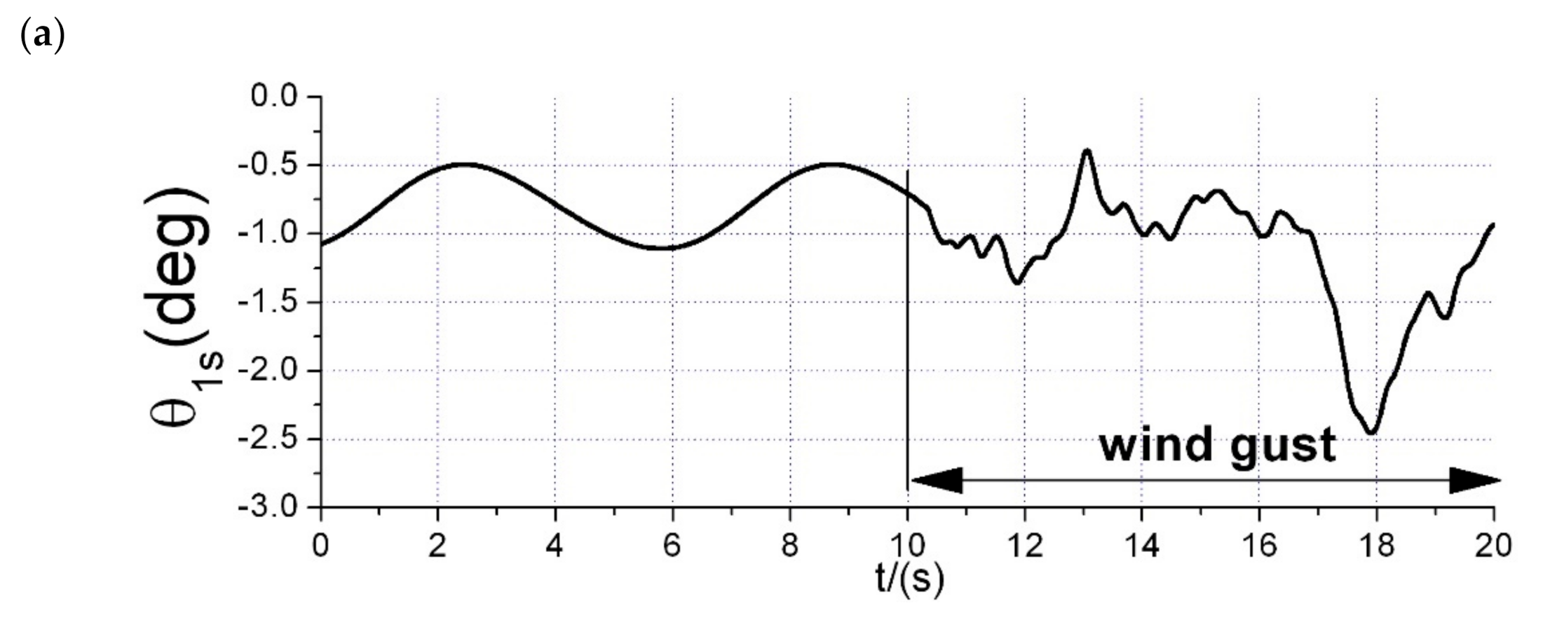
6. Flight Test Experiment
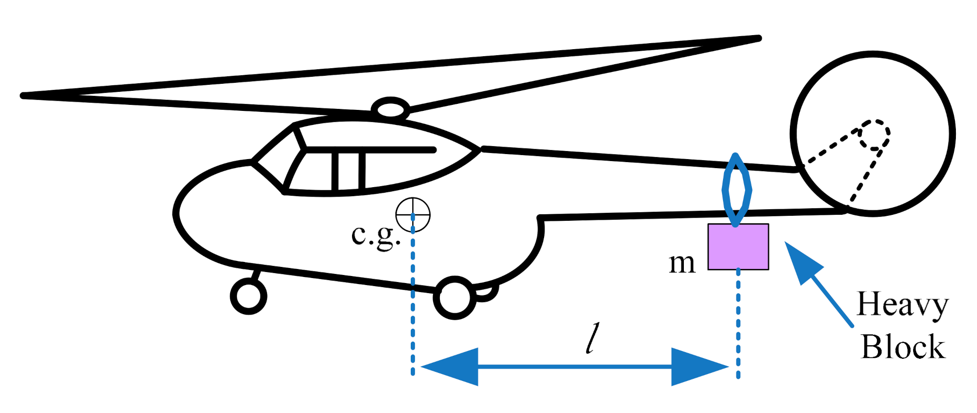
6.1. Testbed Design

The environmental disturbances and nonlinear aerodynamic forces are difficult to generate, replicate and analyze in the disturbance rejection experiment. Despite this, a block dropping device was designed to generate a quantifiable and replicable disturbance, as shown in Figure 6.
A model-scale helicopter called Align T-REX500 was chosen to be the flight testbed in this work. It was produced by ALIGN, which is a company founded in Taiwan, China. In addition to this helicopter, the entire system consists of an avionic box, an attitude and heading reference system (AHRS), a radio and a block dropping device. There is a Digital Signal Processor TM320F2812 developed by Texas Instruments (TI) in the avionic box, which is used to realize the control algorithm, analyze sensor information from the AHRS and generate pulse width modulation (PWM) signals to control the helicopter. And TI is a semiconductor company founded in Texas, USA. The AHRS consists of a three-axis gyroscope, a three-axis accelerometer, a three-axis magnetometer, a barometric altimeter and a microcontroller unit (MCU), which is able to provide the information of attitude and angular velocity. The command signal could be transmitted through the radio. Both the AHRS and the radio were connected to the DSP through RS232. The program was developed in embedded C for DSP by an Integrated Development Environment (IDE) called Code Composer Studio (CCS), which is also provided by TI.
The dropping device is made of a heavy block and a servo, while the block is fixed by the servo, which is controlled by the signal from radio. In this work, the mass of the block is m = 0.26   k g and the distance from the block to the center of gravity is l = 0.4   m , therefore, the disturbance generated by the device, Q D = m g l = 1.02   N m , is sufficiently intense for this testbed. The whole experimental system is shown in Figure 7.

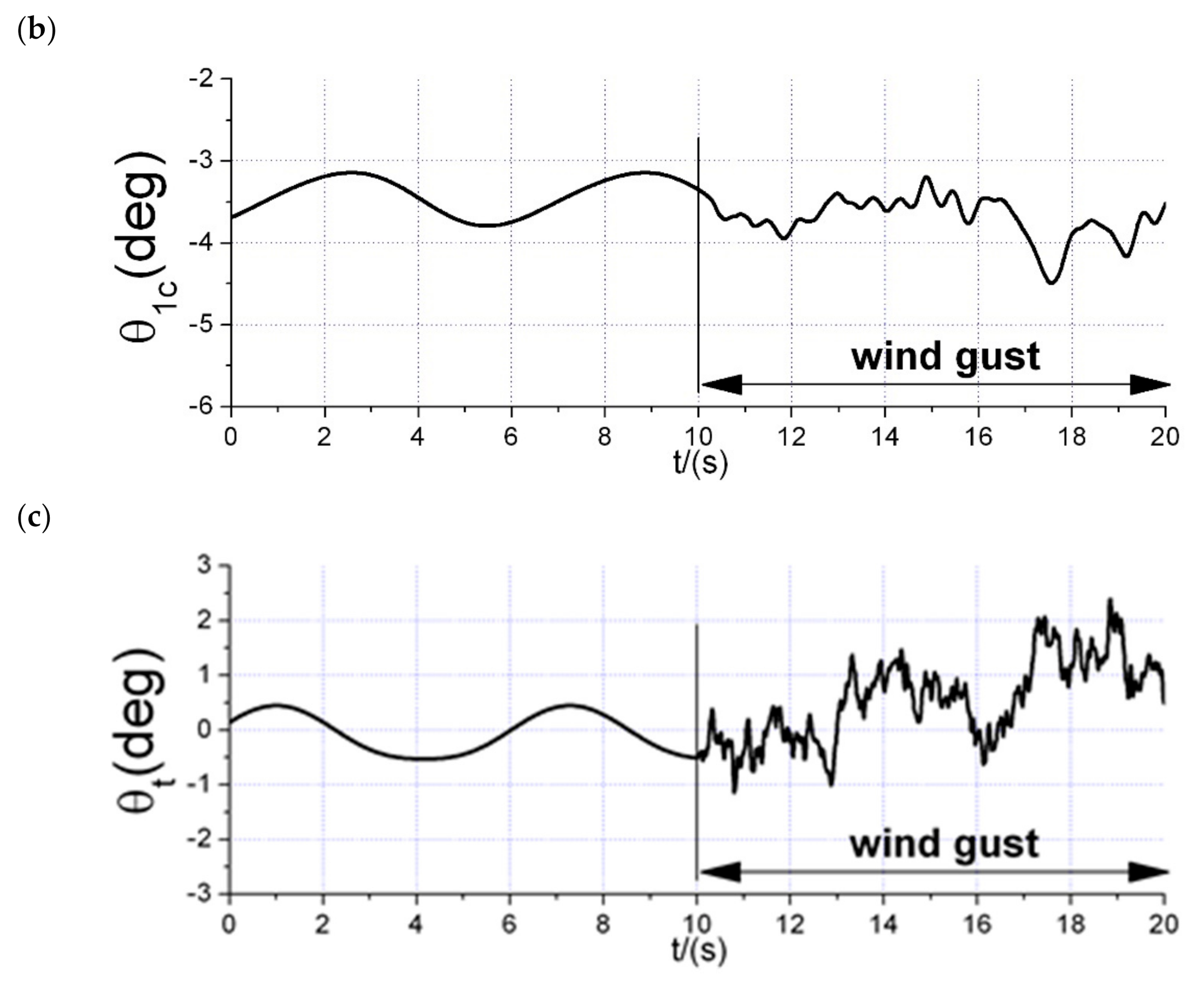
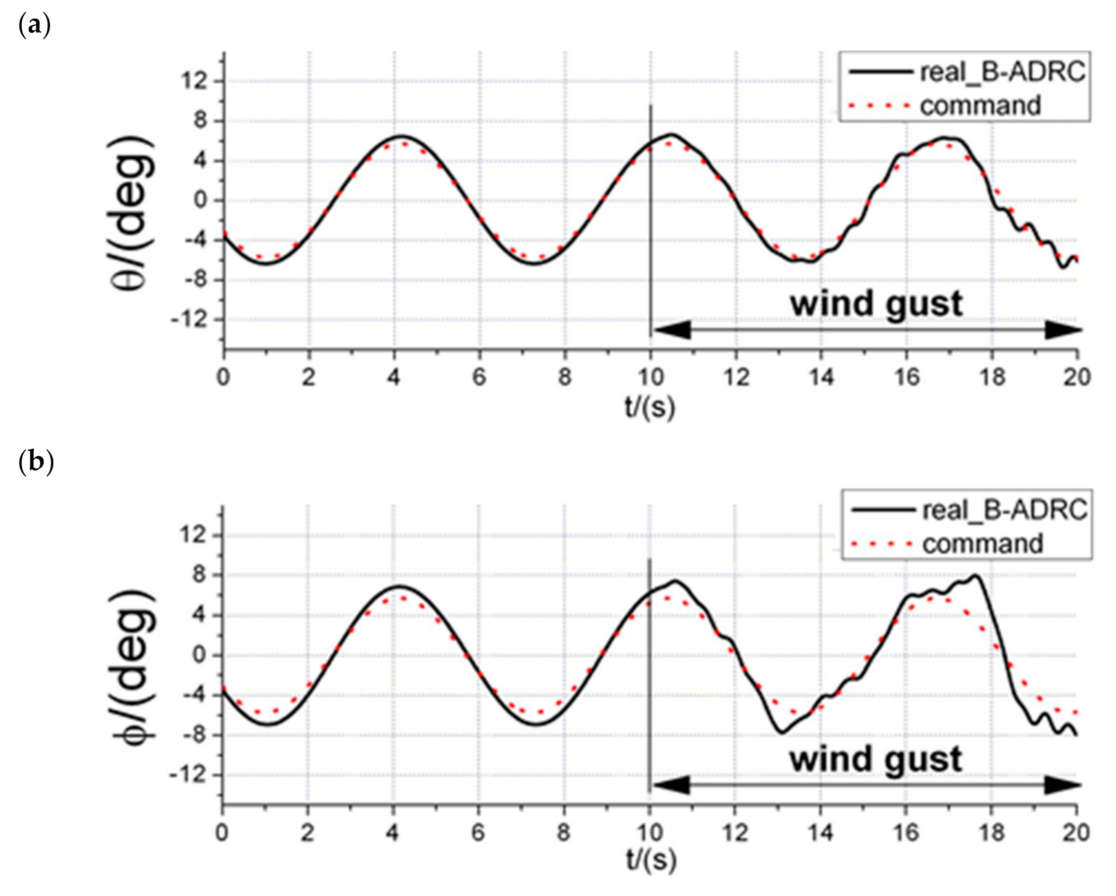
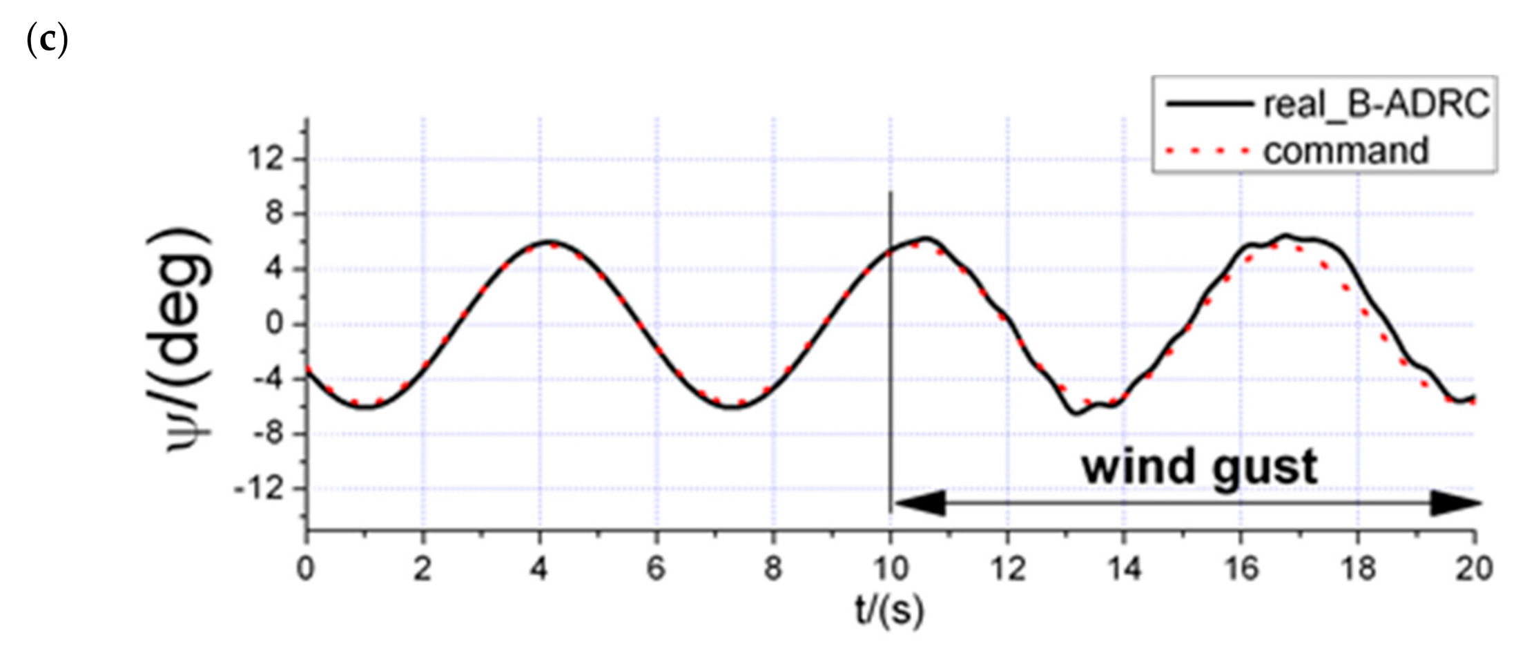
6.2. Disturbance Rejection Experiments

There were three steps in this disturbance rejection experiment. First, a constant attitude command was applied to the control system to keep the helicopter stabilized and hovering. Second, a dropping order was sent to the radio to release the block, which could generate the disturbance. Finally, it waited for a few seconds until the controller corrected the attitude. The procedure is shown in Figure 8.
Both the proposed Backstepping-ADRC and the PID controller with high integral gain were tested under the same conditions. The recorded attitude tracking data, disturbance observation data and the control signal data are illustrated in Figure 9.
For the Backstepping-ADRC, the simulation data coincide with the flight test data validating that the algorithm presented above has excellent performance. According to the attitude tracking data of flight test, the helicopter controlled by the Backstepping-ADRC responded immediately to the disturbance and started to pitch for 0.7 s to the minimum value of −3° until the disturbance was rejected. After that, the helicopter started to recover with a negligible overshoot and settled to a hovering state without steady error. The total settling time for the disturbance (θ within ±1°) was approximately 1.5 s. However, the PID controller with a high integral gain responded with a minimum pitch of −6.5°, an overshoot of 4° and a total settling time of 5 s. During the whole disturbance rejection experiment, the average tracking error of Backstepping-ADRC is 0.39°, while it is 1.68° for the PID controller, and the standard deviations of the tracking errors are 0.74° and 1.83°, respectively. The attitude tracking data suggests that the proposed control algorithm has 78% improvement of control accuracy and 60% improvement of disturbance rejection capability compared to PID control method, and it is able to successfully reject intense and swift disturbances and precisely track the command.
In addition, its rejection is much more efficient and swifter than that of the PID controller. The disturbance observation data could better explain the difference. The observation of the ESO in the Backstepping-ADRC responded rapidly to the disturbance and achieved stable observation within 2 s. In contrast, the integral term of the PID controller responded much slower than the ESO and induced characteristic high magnitude oscillation, resulting in a long settling time and high overshoot of the attitude tracking.

7. Conclusions

This paper proposed a versatile control method to actively reject disturbances and compensate nonlinearities simultaneously without precise system model. The nonlinearities mainly include flapping dynamics, and external disturbances mean wind gust in this article. Both of them were treated as the lumped disturbances. Then, the ESO designed to estimate the lumped disturbances was introduced to eliminate all these adverse factors. Meanwhile, a backstepping controller was applied to achieve attitude tracking based on Lyapunov theory, the separation of disturbance rejection with attitude tracking control guarantees both robustness and performance.
Simulation results show that the control scheme presented above can achieve a good attitude tracking performance, the tracking delay is quite small, while the means and standard deviations of tracking error are also much smaller than PID control, and the maximum value of tracking error is less than 3°. Flapping dynamics and wind gust can be accurately estimated by the ESO, while the delay is less than 0.2 s. Additionally the controller still works well under model uncertainty. According to the flight data, the proposed algorithm is capable of addressing external disturbances rapidly. When compared to the PID method, it also shows better tracking performance and stronger robustness to reject disturbances. However, there still exists some shortcomings in the proposed control scheme. Although the number of the parameters is not too much, all these parameters are adjusted manually based on personal experience, which costs a lot of time and easily goes wrong. Besides, the controller does not consider the situation of input saturation, which may lead to a control failure.
To eliminate the above limitations, intelligent algorithm will be considered to incorporate with the parameter adjustment, such as reinforcement learning, and input saturation will be treated as the constraint in the control system design. Another future work of our paper is to design position and velocity controller to achieve trajectory tracking. The ESO will also be applied to the out-loop controller to deal with the disturbances exerted on them. More flight experiments will be taken to verify the effectiveness of the algorithm.

Author Contributions

Conceptualization, W.Z. and Z.M.; methodology, W.Z. and H.Z.; software, validation, formal analysis, W.Z. and K.W.; writing—original draft preparation, W.Z.; writing—review and editing, W.Z. and K.W.; visualization, K.W. and H.Z.; supervision, project administration, funding acquisition, Z.M. All authors have read and agreed to the published version of the manuscript.

Funding

This work was supported by the National Natural Science Foundation (NSF) of China (No. 61976014).

Institutional Review Board Statement

Not applicable.

Informed Consent Statement

Not applicable.

Data Availability Statement

The fight data presented in this paper are available on request from the first author.

Conflicts of Interest

The authors declare no conflict of interest.

References

  1. García, R.; Rubio, F.; Ortega, M. Robust PID Control of the Quadrotor Helicopter. IFAC Proc. Vol. 2012, 45, 229–234. [Google Scholar] [CrossRef] [Green Version]
  2. Martins, L.; Cardeira, C.; Oliveira, P. Linear Quadratic Regulator for Trajectory Tracking of a Quadrotor. IFAC PapersOnLine 2019, 52, 176–181. [Google Scholar] [CrossRef]
  3. Xu, J.; Cai, C.; Cai, G.; Zou, Y. Robust H-infinity control for miniature unmanned aerial vehicles at hover by the finite frequency strategy. IET Control Theory Appl. 2016, 10, 190–200. [Google Scholar] [CrossRef]
  4. Jeong, D.Y.; Kang, T.; Dharmayanda, H.R. H-Infinity Attitude Control System Design for a Small-Scale Autonomous Heli-copter with Nonlinear Dynamics and Uncertainties. J. Aerosp. Eng. 2012, 25, 501–518. [Google Scholar] [CrossRef]
  5. Tao, L.; Lin, D.; Tao, D. Finite-time control for small-scale unmanned helicopter with disturbances. Nonlinear Dyn. 2019, 96, 1747–1763. [Google Scholar]
  6. Fang, X.; Wu, A.; Shang, Y.; Dong, N. A novel sliding mode controller for small-scale unmanned helicopters with mismatched disturbance. Nonlinear Dyn. 2015, 83, 1053–1068. [Google Scholar] [CrossRef]
  7. Wan, M.; Chen, M.; Yan, K. Adaptive Sliding Mode Tracking Control for Unmanned Autonomous Helicopters Based on Neural Networks. Complexity 2018, 2018, 1–11. [Google Scholar] [CrossRef]
  8. Yan, K.; Chen, M.; Wu, Q.; Zhu, R. Robust adaptive compensation control for unmanned autonomous helicopter with input saturation and actuator faults. Chin. J. Aeronaut. 2019, 32, 2299–2310. [Google Scholar] [CrossRef]
  9. Mallikarjunan, S.; Nesbitt, B.; Kharisov, E.; Xargay, E.; Hovakimyan, N.; Cao, C. L1 Adaptive Controller for Attitude Control of Multirotors. In AIAA Guidance, Navigation, and Control Conference; American Institute of Aeronautics and Astronautics: Reston, VA, USA, 2012; p. 4831. [Google Scholar]
  10. Ullah, I.; Pei, H.-L. Fixed Time Disturbance Observer Based Sliding Mode Control for a Miniature Unmanned Helicopter Hover Operations in Presence of External Disturbances. IEEE Access 2020, 8, 73173–73181. [Google Scholar] [CrossRef]
  11. Jiang, T.; Lin, D.; Song, T. Novel integral sliding mode control for small-scale unmanned helicopters. J. Frankl. Inst. 2019, 356, 2668–2689. [Google Scholar] [CrossRef]
  12. Yu, X.; Yang, J.; Li, S. Disturbance observer-based autonomous landing control of unmanned helicopters on moving shipboard. Nonlinear Dyn. 2020, 102, 131–150. [Google Scholar] [CrossRef]
  13. Joelianto, E.; Sumarjono, E.M.; Budiyono, A.; Penggalih, D.R. Model predictive control for autonomous unmanned helicopters. Aircr. Eng. Aerosp. Technol. 2011, 83, 375–387. [Google Scholar] [CrossRef]
  14. Seo, J.; Lee, S.; Lee, J.; Choi, J. Nonaffine Helicopter Control Design and Implementation Based on a Robust Explicit Nonlinear Model Predictive Control. IEEE Trans. Control Syst. Technol. 2021, 1–8. [Google Scholar] [CrossRef]
  15. Dutta, L.; Das, D.K. Adaptive model predictive control design using multiple model second level adaptation for parameter estimation of two-degree freedom of helicopter model. Int. J. Robust Nonlinear Control 2021, 31, 3248–3278. [Google Scholar] [CrossRef]
  16. Manzoor, T.; Xia, Y.; Zhai, D.-H.; Ma, D. Trajectory tracking control of a VTOL unmanned aerial vehicle using offset-free tracking MPC. Chin. J. Aeronaut. 2020, 33, 2024–2042. [Google Scholar] [CrossRef]
  17. Manzoor, T.; Sun, Z.; Xia, Y.; Ma, D. MPC based compound flight control strategy for a ducted fan aircraft. Aerosp. Sci. Technol. 2020, 107, 106264. [Google Scholar] [CrossRef]
  18. Hu, Y.; Yang, Y.; Li, S.; Zhou, Y. Fuzzy controller design of micro-unmanned helicopter relying on improved genetic optimi-zation algorithm. Aerosp. Sci. Technol. 2020, 98, 105685. [Google Scholar] [CrossRef]
  19. Jiang, F.; Pourpanah, F.; Hao, Q. Design, Implementation, and Evaluation of a Neural-Network-Based Quadcopter UAV System. IEEE Trans. Ind. Electron. 2020, 67, 2076–2085. [Google Scholar] [CrossRef]
  20. Pi, C.-H.; Hu, K.-C.; Cheng, S.; Wu, I.-C. Low-level autonomous control and tracking of quadrotor using reinforcement learning. Control Eng. Pr. 2020, 95, 104222. [Google Scholar] [CrossRef]
  21. Cao, L.; Hu, X.; Zhang, S.; Liu, Y. Robust Flight Control Design Using Sensor-Based Backstepping Control for Unmanned Aerial Vehicles. J. Aerosp. Eng. 2017, 30, 04017068. [Google Scholar] [CrossRef]
  22. Wang, X.; Yu, X.; Li, S.; Liu, J. Composite block backstepping trajectory tracking control for disturbed unmanned helicopters. Aerosp. Sci. Technol. 2019, 85, 386–398. [Google Scholar] [CrossRef]
  23. Labbadi, M.; Cherkaoui, M. Robust adaptive backstepping fast terminal sliding mode controller for uncertain quadrotor UAV. Aerosp. Sci. Technol. 2019, 93, 105306. [Google Scholar] [CrossRef]
  24. Eliker, K.; Zhang, W. Finite-time Adaptive Integral Backstepping Fast Terminal Sliding Mode Control Application on Quadrotor UAV. Int. J. Control Autom. Syst. 2020, 18, 415–430. [Google Scholar] [CrossRef]
  25. Pi, C.-H.; Ye, W.-Y.; Cheng, S. Robust Quadrotor Control through Reinforcement Learning with Disturbance Compensation. Appl. Sci. 2021, 11, 3257. [Google Scholar] [CrossRef]
  26. Zhang, Z.; Wang, F.; Guo, Y.; Hua, C. Multivariable sliding mode backstepping controller design for quadrotor UAV based on disturbance observer. Sci. China Inf. Sci. 2018, 61, 112207. [Google Scholar] [CrossRef]
  27. Chen, F.; Lei, W.; Zhang, K.; Tao, G.; Jiang, B. A novel nonlinear resilient control for a quadrotor UAV via backstepping control and nonlinear disturbance observer. Nonlinear Dyn. 2016, 85, 1281–1295. [Google Scholar] [CrossRef]
  28. Han, J. A class of extended state observers for uncertain systems. Control Decis. 1995, 10, 85–88. [Google Scholar]
  29. Alexis, K.; Papachristos, C.; Siegwart, R.; Tzes, A. Robust Model Predictive Flight Control of Unmanned Rotorcrafts. J. Intell. Robot. Syst. 2015, 81, 443–469. [Google Scholar] [CrossRef]
  30. Xian, B.; Guo, J.; Zhang, Y.; Zhao, B. Sliding mode tracking control for miniature unmanned helicopters. Chin. J. Aeronaut. 2015, 28, 277–284. [Google Scholar] [CrossRef] [Green Version]
  31. Sheng, S.; Sun, C. An adaptive attitude tracking control approach for an unmanned helicopter with parametric uncertainties and measurement noises. Int. J. Control Autom. Syst. 2016, 14, 217–228. [Google Scholar] [CrossRef]
  32. Shao, S.; Chen, M. Adaptive Neural Discrete-Time Fractional-Order Control for a UAV System with Prescribed Performance Using Disturbance Observer. IEEE Trans. Syst. Man Cybern. Syst. 2021, 51, 742–754. [Google Scholar] [CrossRef]
  33. Maqsood, H.; Qu, Y. Nonlinear Disturbance Observer Based Sliding Mode Control of Quadrotor Helicopter. J. Electr. Eng. Technol. 2020, 15, 1453–1461. [Google Scholar] [CrossRef]
  34. Fang, X.; Wu, A.; Shang, Y.; Dong, N. Robust control of small-scale unmanned helicopter with matched and mismatched dis-turbances. J. Franklin Inst. 2016, 353, 4803–4820. [Google Scholar] [CrossRef]
  35. Chen, R.T.N. Effects of Primary Rotor Parameters on Flapping Dynamics. NASA TP-1431; NASA: Washington, DC, USA, 1980. [Google Scholar]
  36. Cai, G.; Chen, B.M.; Lee, T.H. Unmanned Rotorcraft Systems; Springer: Berlin/Heidelberg, Germany, 2011; pp. 107–110. [Google Scholar]
  37. Johnson, W. Helicopter Theory; Courier Dover Publications: New York, NY, USA, 2012; pp. 45–72. [Google Scholar]
  38. Beal, T.R. Digital simulation of atmospheric turbulence for Dryden and von Karman models. J. Guid. Control Dyn. 1993, 16, 132–138. [Google Scholar] [CrossRef]
  39. Avanzini, G.; Matteis, G.D. Two-timescale inverse simulation of a helicopter model. J. Guid. Control Dyn. 2001, 24, 330–339. [Google Scholar] [CrossRef]
  40. Han, J. Active Disturbance Rejection Control Technique—The Technique for Estimating and Compensating the Uncertain-Ties; National Defense Industry Press: Beijing, China, 2008; pp. 183–242. [Google Scholar]
Figure 1. Wind gust based on Dryden spectral model. (a) Wind gust in longitudinal direction; (b) wind gust in lateral direction.
Applsci 11 05331 g001aApplsci 11 05331 g001b
Figure 2. Attitude tracking without uncertainties. (a) Tracking of roll angle; (b) tracking of pitch angle; (c) tracking of yaw angle.
Applsci 11 05331 g002
Figure 3. Disturbances observation without uncertainties. (a) Estimation of f1; (b) estimation of f2; (c) estimation of f3.
Applsci 11 05331 g003
Figure 4. Control inputs without uncertainties. (a) Lateral control input; (b) longitudinal control input; (c) yaw control input.
Applsci 11 05331 g004aApplsci 11 05331 g004b
Figure 5. Attitude tracking with model uncertainty. (a) Tracking of pitch angle; (b) tracking of roll angle; (c) tracking of yaw angle.
Applsci 11 05331 g005aApplsci 11 05331 g005b
Figure 6. The structure diagram of block dropping system.
Applsci 11 05331 g006
Figure 7. The testbed of model helicopter with dropping device.
Applsci 11 05331 g007
Figure 8. The block dropping procedure of the experiment. (a) Hovering before dropping the block; (b) the moment after dropping the block.
Applsci 11 05331 g008
Figure 9. Flight test data of disturbance rejection (I_PID denotes the integral term of the PID controller). (a) Tracking of pitch angle; (b) estimation of disturbance; (c) longitudinal cyclic pitch angle of main rotor.
Applsci 11 05331 g009
Table 1. Model parameters.
ParameterDescriptionValue
I x x , I y y , I z z Moments of inertia 0.0541 ,   0.0607 , 0.1601 ( k g m 2 )
MGross weight2.8(kg)
RmRadius of main rotor0.485(m)
( L u , L v )Turbulence scale length23.6, 23.6
( σ u , σ v )The turbulence intensities0.99, 0.99
UReference air speed5(m/s)
R 12 , R 3 Control input coefficients 34.48 185.79 150.19 35.91 , 12.48
Table 2. Controller parameters.
ParameterDescriptionValue
K 1 P Control parameter matrix 1diag(6,6,6)
K 2 P Control parameter matrix 2diag(4,4,4)
B 01 Feedback parameter matrix 1 for ESOdiag(200,200,200)
B 02 Feedback parameter matrix 2 for ESOdiag(1400,1400,1400)
Publisher’s Note: MDPI stays neutral with regard to jurisdictional claims in published maps and institutional affiliations.

