Article

Diamond-Shaped Extended Fins for Heat Transfer Enhancement in a Double-Pipe Heat Exchanger: An Innovative Design

1
Department of Mathematics, Vehari Campus, COMSATS University Islamabad, Mailsi Road, Vehari 61100, Pakistan
2
Centre for Advanced Studies in Pure and Applied Mathematics, Bahauddin Zakariya University, Multan 60800, Pakistan
3
Department of Mathematics, Emerson University Multan, Multan 60700, Pakistan
*
Author to whom correspondence should be addressed.
Appl. Sci. 2021, 11(13), 5954; https://doi.org/10.3390/app11135954
Submission received: 28 April 2021 / Revised: 20 May 2021 / Accepted: 25 May 2021 / Published: 26 June 2021
(This article belongs to the Special Issue Dynamic Phenomena)

Abstract

:
Heat transfer enhancement in heat exchangers results in thermal efficiency and energy saving. In double-pipe heat exchangers (DPHEs), extended or augmented fins in the annulus of the two concentric pipes, i.e., at the outer surface of the inner pipe, are used to extend the surface of contact for enhancing heat transfer. In this article, an innovative diamond-shaped design of extended fins is proposed for DPHEs. This type of fin is considered for the first time in the design of DPHEs. The triangular-shaped and rectangular-shaped fin designs of DPHE, available in the literature, can be recovered as special cases of the proposed design. An h-adaptive finite element method is employed for the solution of the governing equations. The results are computed for various performance measures against the emerging parameters. The results dictate that the optimal configurations of the diamond-shaped fins in the DPHE for an enhanced heat transfer are recommended as follows: If around 4–6, 8–12, or 16–32 fins are to be placed in the DPHE, then the height of the fins should be 20%, 80%, or 100%, respectively, of the annulus width. If frictional loss of heat is also to be considered, then for fin-heights of 20–80% and 100% of the annulus width, the placement of 4 and 8 diamond-shaped fins, respectively, is recommended for an enhanced heat transfer. These recommendations are for the radii ratio (i.e., the ratio of the inner pipe radius to that of the outer pipe) of 0.25. The recommendations are be modified if the radii ratio is altered.

1. Introduction

Heat exchangers are the apparatus used in many industries for heat transfer among fluids. In the design process of heat equipment, such as boilers, nuclear-reactor cores, radiators, condensers, and air conditioners, heat transfer engineering analysis is necessary [1]. Heat transfer enhancement in heat exchangers results in thermal efficiency and energy saving. A double-pipe heat exchanger (DPHE) is a special kind of heat exchanger with two concentric pipes, one inside the other. There are two different fluid flows in a DPHE, such that one fluid flows inside the inner pipe and the other fluid flows in the annulus region outside of the inner pipe. There is a growing need to decrease the cost and size of heat exchangers and increase the heat transfer characteristics. The performance of heat exchangers can be enhanced by adopting appropriate techniques. These techniques include the use of extended surfaces, surface vibration, rough surfaces, and coiled tubes. The present work deals with the technique of using the extended fins. These fins are extended surfaces and employed to increase the heated surface. A brief survey of some existing forms of heat exchanger extended fins is presented below.
The authors of [2,3] proposed increasing the heat transfer using triangular fins in straight pipes. They adopted the finite element (FE) technique for numerical results. They decomposed the problem into two parts. In the first part [2], they presented the analysis for the following parameters: the number, thickness, and height of the fins. They also suggested empirical relationships for the friction factor. In the second part [3], they analyzed the heat transfer characteristics by assuming the condition of axially uniform heat flux. This type of thermal boundary condition is known as the H1 boundary condition (Shah and London [4]). They reported an optimum number of fins for enhanced values of the Nusselt number (Nu). Soliman et al. [5] reported the increase of the coefficient of heat transfer using the tapered longitudinal fins in tubes. They applied the condition of constant wall temperature. They also compared their suggested results with a finless pipe. The thermal boundary condition considered in [5] is known as the T1 boundary condition. Sparrow and Charmchi [6] performed the analysis of heat enhancement in a pipe with annular fins. These fins were augmented externally and arranged in arrays with regular space. They employed the Biot number for heat analysis. They reported a substantial rise in the Biot number as compared to the finless tube. Parkash and Liu [7] carried out the study of heat enhancement of laminar flow at the entry section of a duct. They assumed radial fins of zero thickness. They presented results for a number of radial fins varying from 8 to 24. Tao [8] discussed the combined convection and conduction heat exchange analysis in a finned pipe. He reported that fins augmented internally cause a significant effect on heat exchange. Agrawal and Sengupta [9] investigated the heat and flow analysis in a pipe with augmented periodic fins. They considered the values of fin-gap, fin-height, and radii ratio in the range of 2 to 5, 0.33 to 0.67, and 0.3 to 0.5, respectively. They reported that recirculating flow was observed in the whole fin-inter spacing for the Reynolds number (Re) greater than 500, and a 3.1 times rise in heat transfer for specific parametric values. Suryanarayana and Apparao [10] experimentally investigated the pressure drop in terms of pumping power in a DPHE. They considered rectangular fins having interruptions. They reported that the coefficient of heat exchange rises with an increasing number of interruptions. Syed [11] investigated the heat exchange numerically in a DPHE with rectangular fins. He proposed that the height and thickness of the fins may also be considered along with hydraulic diameter to form the correlation of coefficient of heat exchange. The longitudinal fins augmented internally in the tube, in the form of a wave structure, were investigated experimentally by Yu et al. [12]. They studied the characteristics of pressure and heat in both regions: fully developed and entry. They considered Re in the range of 900 to 3500 and reported that the fins’ wave structure raises the heat transfer. Nasiruddin and Siddiqui [13] proposed the idea of using baffle to increase the rate of heat exchange in the tube. They considered three arrangements of the baffles. They concluded that baffles arranged in an inclined downstream manner exhibit a significant role in heat enhancement. Syed et al. [14] numerically examined heat transfer characteristics at the entrance region of a finned DPHE. A triangular-shaped finned DPHE was studied by Syed et al. [15] for laminar convection. They numerically simulated the fully developed, steady, and laminar flow in the DPHE with constant heat flux at the boundary. Ishaq et al. [16] carried out a simulation of laminar convection in an annulus of DPHE with triangular fins of different heights. Iqbal et al. [17] presented various optimal designs of finned DPHEs. They considered various configurations of fins in the DPHE. They used the finite element method for numerical solutions. Ishaq et al. [18] numerically studied the conjugate heat analysis in the triangular-finned DPHE. They reported that the thermal performance of the proposed DPHE is dependent on the ratio of thermal conductivities. Hamed et al. [19] numerically performed the experiments to study the pressure drop and heat characteristics in DPHE using nanofluid, vortex generators, and twisted tape. They reported that heat transfer characters showed a significant increase due to variation in the vortex generation. Maakoul et al. [20] investigated the thermal performance of DPHE using interruptions. These are generated by splitting the longitudinal fins (SLF). They showed that a significant enhancement in the rate of heat transfer due to SLF as compared to simple longitudinal fins. Karoueia and Ajarostaghi [21] investigated the flow and the characteristics of heat transfer in DPHE having a swirl generator. They used 12 blades with holes in the turbulator for swirl flow. They concluded that swirl flow due to the turbulator had shown significant effectiveness in the enhancement of heat. Dalkılıç et al. [22] studied the geometry, number, and dimensions of fins in the DPHE using various nanoparticles for promotion of heat transfer. Luo and Song [23] proposed and investigated the heat transfer problem in the oval annulus of a double-tube heat exchanger. They reported their results in terms of aspect and twist ratios of the annuli. Poongavanam and Kim [24] performed pressure drop and heat analysis in a DPHE having shot peening. They reported an up to 1.19 times enhancement in the thermal performance of the proposed design.
The diamond fin shape in the present work is considered the first time in the literature for the flow regime in double-pipe heat exchangers. The objective of the present work is to study the characteristics of convective heat transfer in the annular region of a finned DPHE with an innovative diamond-shaped fin design. The diamond-shaped fins are longitudinally augmented on the outer surface of the inner pipe of the DPHE. The configuration of the diamond-finned annulus is determined by the various values of the geometrical parameters, such as the radii ratio ( R ^ ), number of fins ( N ), fin-height ( l * ), and fin thickness ( β ). The effects of these parameters on various performance measures, such as the product of the Reynolds number and friction factor, Nusselt number, and j -factor, are computed. The model equations are solved using an h-adaptive finite element method. The rest of the article is structured as follows. The problem geometry, the governing partial differential equation with the corresponding boundary conditions, and finite element scheme are described in Section 2. Section 3 presents the results and discussion. Finally, the conclusion is given in Section 4.

2. Materials and Methods

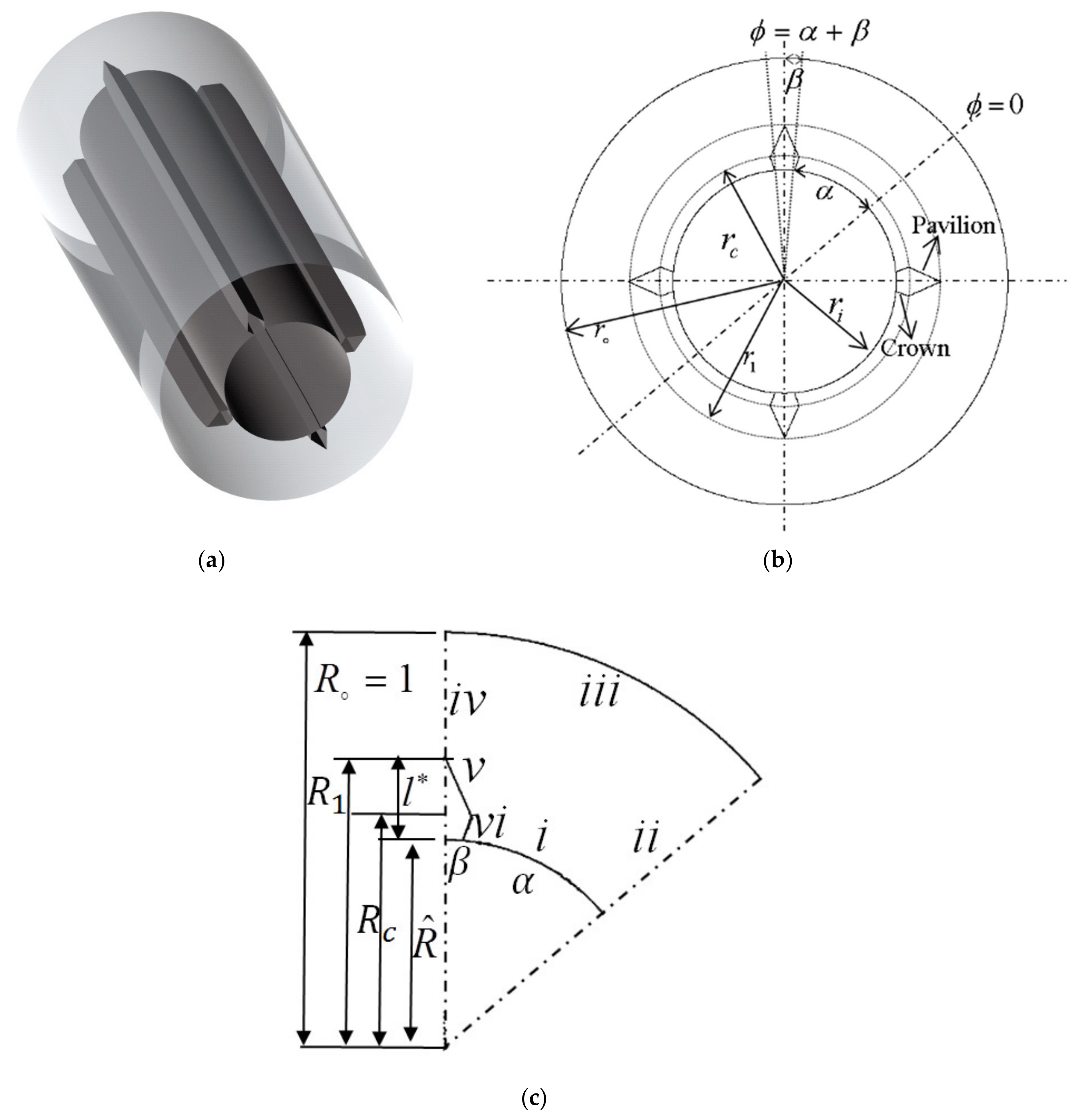
2.1. Problem Description

A DPHE with four diamond-shaped fins is shown in Figure 1a. These are augmented longitudinally and distributed uniformly at the inner pipe surface. These fins are non-porous, non-empty, and straight. The material of the pipes and fins is considered the same and assumed to be highly conductive. The thickness of the pipes is assumed to be negligible. The cross-section of the proposed DPHE with four diamond fins is illustrated in Figure 1b. We highlighted two surfaces relevant to a diamond-shaped fin: the crown surface and the pavilion surface. The angles α and β represent the angle between two consecutive fins and the fin half-angle, respectively. In the present work, the crown height was set as 30% of the overall fin-height, and the crown angle was set as 6% of the angle α . The computational domain, chosen due to symmetry, is presented in Figure 1c. The fluid motion was considered as steady, laminar, and fully developed. The length of DPHE was sufficient to guarantee that the flow becomes fully developed. Viscous dissipation and body forces were ignored. The density and viscosity of the fluid were considered constant. The thermal boundary condition imposed at the inner pipe was constant heat input per unit axial length with the circumferentially constant temperature at any cross-section. Due to the assumption of highly conductive material of the diamond fins and inner pipe, this thermal condition may be assumed to be imposed at the interface of the inner pipe-diamond fin assembly and the fluid. At the outer pipe, an adiabatic thermal boundary condition was considered. The edges at which the boundary conditions were imposed are mentioned i to v i in Figure 1c. The governing equations are described below with the corresponding boundary conditions.
The momentum equation:
2 U r 2 + 1 r U r + 1 r 2 2 U 2 = 1 μ d p d z
The energy equation:
1 r r r T r + 1 r 2 2 T 2 + 2 T z 2 = 1 k U T z
The corresponding boundary conditions are given by:
(i) U = 0   and   T = T w z   at   r = r i   and   0 φ α (ii) U = 0   and   T = 0   at   r i r r o   and   φ = 0 (iii) U = 0   and   T r = 0   at   r = r o   at   0 φ α + β (iv) U = 0   and   T = 0   at   r i r r o ,   φ = α + β (v) U = 0   and   T = T w z   at   r = r c r i   sin θ 1 r i   sin φ α + r c sin α θ 1 φ   and   α θ 1 φ α (vi) U = 0   and   T = T w z   at   r = r c r 1   sin θ 1 + β r 1   sin α + β φ + r c sin φ α + θ 1   and   α θ 1 φ α + β
The following dimensionless variables are defined for non-dimensionalization of the model Equations (1)–(3):
R = r r o , R ^ = r i r o , R 1 = r 1 r o , R c = r c r o , U * = U U m a x , τ * r = T r , z T w z Q ´ / λ f
where U m a x = 1 4 μ d p d z r 0 2 1 R m 2 + 2 R m 2 l n R m is the maximum velocity, with R m = r m r 0 = 1 R ^ 2 2 ln 1 / R ^ . Applying these dimensionless variables in Equations (1)–(3), the resulting dimensionless governing equations with the associated conditions are given by:
1 R U * R + 2 U * R 2 + 1 R 2 2 U * 2 = 4 C
2 τ * R 2 + 1 R τ * R + 1 R 2 2 τ * 2 = U * A * c U ¯ *
The corresponding boundary conditions are given by:
(i) U * = 0   and   τ * = 0   at   R = R ^   and   0 φ α (ii) U * = 0 and τ * = 0   at   R ^ R 1   and   = 0 (iii) U * = 0   and   τ * R = 0   at   R = 1   and   0 φ α + β (iv) U * = 0 and τ * = 0   at   R 1 R 1   and   φ = α + β (v) U * = 0   and   τ * = 0   at   R = R c R ^   sin θ 1 R ^   sin φ α + R c sin α θ 1 φ   and   α θ 1 φ α (vi) U * = 0   and   τ * = 0   at   R = R c R 1   sin θ 1 + β R 1   sin α + β φ + R c sin φ α + θ 1   and   α θ 1 φ α +   β
where U * , τ * , and U ¯ * are the dimensionless velocity, dimensionless temperature, and average dimensionless velocity, respectively. Moreover, C is defined by 1 R m 2 + 2 R m 2 l n R m .

2.2. Finite Element Formulation

In this section, the adopted numerical method based on the finite element method (FEM) is employed for numerical investigation of characteristics of flow and heat transfer in the diamond-shaped finned DPH.
FEM was introduced to find the solution of structural engineering problems. With the passage of time, the development of this method made it so powerful that it is extensively employed to solve governing partial differential equations of the problems from various fields, such as fluid mechanics, wave propagation, reaction–diffusion and convection–diffusion processes, and in many other fields. The basic steps involved in the computation of elliptic PDE using FEM are: describing the numerical domain; generating the triangular mesh in the computational domain; discretizing the given equation; the corresponding boundary conditions are adjusted to form the system of equations. For the present problem, the h-adaptive procedure was used to compute more accurate solutions. It may be noted that the governing momentum and energy equations of this present heat transfer problem are elliptic in nature. FEM formulation of an elliptic model PDE is presented as follows. Consider the elliptic model PDE,
  c u + a u = f
in the domain D , where c , a , u , and f are functions defined on D . The Dirichlet and generalized Neumann conditions are imposed on the solid surface and the line of symmetry, respectively. These are mathematically expressed by h u = r and n   c u + q u = g , respectively, on the edge Γ of the domain D , where h , r , q , and g are defined on the boundary Γ and n is the unit normal. The Dirichlet condition can be approximated from the generalized Neumann boundary condition, and thus, the latter is assumed on the whole boundary, Γ . Multiplying Equation (8) with a test function ψ and integrating on D , gives
D   c u ψ + a u ψ d x = D f ψ d x
Integrating by parts yields
D c u   ψ + a u ψ d x Γ n   c u ψ d s = D f ψ d x
Implementing the boundary condition:
D c u   ψ + a u ψ d x Γ q u + g ψ d s = D f ψ d x
The weak form of the model equation is as below, after simplification:
D c u   ψ + a u ψ d x D f ψ d x Γ q u + g ψ d s = 0 ,             ψ
where u and ψ belong to finite-dimensional subspace V M of a function space V , which is the collection of those square-integrable continuous functions that disappear on the Dirichlet boundary. The approach of choosing u and ψ from the same subspace is called the Galerkin approach. Hence, u can be expressed as u x = j = 1 M u j ψ j x , where u j and ψ j are the scalar coefficients and linear basis functions, respectively. After substituting the solution approximation u x , the resulting system of an algebraic equation is given by
j = 1 M D c ψ j   ψ i + a ψ j ψ i d x + Γ q ψ j ψ i d s u j = D f ψ i d x + Γ g ψ i d s ,             ψ
where the system (13) is represented in the matrix notation as K + M + Q U = F + G , where K i j = D c ψ j   ψ i d x , M i j = D a ψ j ψ i d x , Q i j = Γ q ψ j ψ i d s , F i j = D f ψ i d x , and G i j = Γ g ψ i d s .
To compute the solution of the problem, the formulation (13) is considered with the relevant boundary conditions. On comparing the momentum and energy equations with the elliptic Equation (8), the values of c and a are 1 and 0 , respectively, whereas f has its expressions accordingly. Moreover, g = q = r = 0 and h = 1 are due to the prescribed boundary conditions.

2.3. h-Adaptation and Grid Independence Test

For computing the results for the proposed DPHE, the h -adaptive finite element approach was employed. In the computational domain, an initial triangular mesh is generated. In the process of h -adaptation, firstly, the solution in terms of f R e is computed on the initial mesh, and the mesh is flagged on the basis of error estimates for uniform mesh refinement. In this refinement, each flagged triangle is further refined into four sub-triangles. A detailed description of this adaptive process is given in Section 3 of [15]. Figure 2 presents the results of the grid independence test for R ^ = 0.5 and β = 3 with 4–32 diamond fins of height 40% of the annulus width. It may be noted that for each configuration of the diamond-shaped fin, the computational domain is altered, and hence, the triangular mesh and its adaptive form (as evident from the last column of Table 1).

2.4. Validation of Computed Results

A self-developed computer program based on the “Partial Differential Equations Toolbox of MATLAB®” was employed in the present investigation. The program is already validated in [15] for the cases of the annulus of double pipe without fins, the annular sector, and very thin finned annulus. Moreover, in the present problem, if both crown height and angle of the diamond fin are assumed to be zero, then the present problem corresponds to triangular-finned annulus [15], and when crown height is considered as a maximum of fin-height, then it presents rectangular-finned annulus [11]. Table 2 shows the comparison of the above-stated cases for specified parameters. The maximum error for the case of the triangular-finned annulus for f R e and N u are 0.48 % and 1.12 % , respectively. For the case of the rectangular-finned annulus, f R e and N u are 0.99 % and 0.83 % , respectively.

3. Results and Discussion

The numerical results of the current problem were computed by employing an h-adaptive finite element method. The results were computed in terms of the product of the Reynolds number and friction factor ( f R e ), Nusselt number ( N u ), and j-factor ( j / f ). These notations correspond to the hydraulic diameter. These parameters, when corresponding to the equivalent diameter, are denoted by placing an e in the subscript, i.e., f R e e , N u e , and j / f e . The influence of the geometric parameters, R ^ , N , l * , and β on the overall heat transfer characteristics of the proposed DPHE were investigated. For different cases of execution, N was varied from 4 to 32, l * was varied from 20% to 100% of the annulus width, i.e., 0.2 l * 1.0 , β was varied from 3 to 5 , and R ^ varies from 0.05 to 0.6 . First, the local results in terms of velocity contours and isotherms are presented for specified values of the parameters to study the local flow behavior and heat transfer characteristics. Although the present computations were performed in a serial fashion, parallelization of the code for parallel computers would reduce the execution time [25].
Figure 3 and Figure 4 display the velocity contours for R ^ = 0.5 , β = 3 , N = 4 ,   12 ,   20 ,   28 , 32 , and 0.2 l * 1.0 . Large velocity gradients at the pipe surfaces and the fin-tip can be observed in Figure 3a. A high velocity region is present in the center of the annulus between two neighboring diamond fins. As the fin-height is 20% of the annulus, therefore, the effect of these fins on the outer pipe is negligible. This is evident from the circular arcs near the outer wall. The fluid flow is looking exactly stagnant in the corners made by the crown surface of the diamond fins and adjacent inner pipe surface. The influence of N on the flow pattern is shown in Figure 3b–d. With an increase in N , the circular streamlines of the high velocity region between two fins gradually mix with each other and look in the form of the annulus of high velocity. At the inner pipe surface, the velocity gradients gradually vanish and thus cause an increase in the stagnant flow region. The influence of the fin-height on the flow pattern in the annulus is demonstrated in Figure 3 and Figure 4. With an increase in the fin-height from 20% to 80% of the annulus, the high velocity region gradually shifts towards the outer wall, and the stagnant flow zone in the vicinity of the fin base decreases. For a higher number of fins, the gap between the outer pipe and the diamond fin tip pushes the high velocity region towards the inner pipe. When the fin-height is 100% of the annulus width, as depicted in Figure 4k–o, the stagnant flow region is observed at the base and tip of each of the fins. From these observations, it is predicted that the fin tip, the upper part of the crown surface, the whole pavilion surface of the diamond fin, and the inner pipe surface away from the fin base play an active role in the convective heat transfer.
For R ^ = 0.5, β = 3, N = 4,12,20,28,32, and 0.2 ≤ 𝑙* ≤ 1.0, the isotherms are shown in Figure 5 and Figure 6. As the definition of temperature 𝑙* shows the difference of fluid and temperature of the wall, the lower values of isotherms in Figure 5 and Figure 6 show high temperature, and the higher values of isotherms indicate low temperature. Figure 5 shows isotherms for R ^ = 0.5, β = 3, N = 4,12,20,28,32, and 𝑙* = 0.2 and 0.4. In Figure 5a, high temperature gradients are observed at the tip, the whole pavilion surface of diamond fins, and the surface of the inner pipe away from the base of diamond fins, showing that there is high heat convection. The negligible heat convection is observed due to very hot fluid in the corner of the crown surface of the fin and the surface of the inner pipe. This supports the stagnant fluid flow in this region. The low temperature isotherms are noted on the outer wall, which are in the form of circular arcs between two consecutive diamond fins. It is reflecting that diamond fins with 20% of annulus width have no significant impact on the temperature distribution near the outer wall. With an increase in N, the high temperature gradients gradually shift from the inner pipe surface to the tip and pavilion, as depicted in Figure 5b–d. In other words, the extent of the stagnant flow area has increased due to the reduction of the gap between two consecutive diamond fins. Moreover, the hotter region near the outer wall increases with increments in N.
The effects of fin-height are depicted in Figure 5 and Figure 6. The height of the diamond fin is increased from 40% to 100% of the annulus width. With an increase in the fin-height, the scorching region near the inner pipe and crown surface of the fin first increases then decreases due to a decrease in the gap between the fin tip and the outer wall. For N ≥ 12, the temperature rises between any two fins near the crown surface, showing negligible convection there. For N ≥ 12, high temperature gradients can be observed at the surface of the inner pipe. Conclusively, the convection rate is high at the fin surface and inner pipe where high velocity gradients exist. Both height and number of diamond fins are found to be influential for heat convection.
Inspection of the present heat transfer system based on the diamond-finned annulus is presented in terms of fRe, Nu, and j/f. fRe is an important parameter that is used for the analysis of pressure drop in a heat exchanger. We computed fRe and fRee on the basis of the diameters D H * and D e * where D H * = 4 A c * w p and D e * = 2 1 R ^ denote the hydraulic and equivalent diameters, respectively, in a dimensionless form as follows:
f R e = 2 D H * 2 C U ¯ *
f R e e = 2 D e * 2 C U ¯ *
Figure 7a,b shows the curves of fRe against N for the specific parameters. For an increase in N, fRe strictly decreases for 0.2 ≤ 𝑙* ≤0.6, and for 𝑙*> 0.6 it shows non-monotonic behavior. With an increase in 𝑙*, fRe shows a decreasing trend for N = 4, fRe shows a wavy trend for 8 ≤ N ≤ 24, and fRe first decreases to attain a respective minimum value and then shows strictly increasing behavior or N > 24. The minimum values of fRe for any choice of fin-height exist for 32 fins. Likewise, 𝑙* = 1.0 gives the minimum value of fRe when N varies from 4 to 12. For N > 12, 𝑙* = 0.4 depicts the lowest values of fRe. With an increase in the thickness of the fin β from 3 to 5, fRe increases for small values of N, and fRe decreases for large values of N. The effect of increasing the radii ratio R ^ are shown in Figure 7b. fRe is higher for higher values of R ^ . The wavy trend of the curves fRe is due to its dependence on the hydraulic diameter.
Figure 7c–d presents the graphs of the normalized fRee against N. The normalized fRee corresponds to a finless annulus. It is useful in understanding the effect of the finned annulus on pressure drop. With an increase in N, the curves of the normalized fRee show a monotonically increasing trend. For 𝑙* = 0.4, the normalized fRee shows a steady rise for 𝑙* = 0.4 and a rapid rise for other values of 𝑙*. The normalized fRee increases with an increase in 𝑙*. The impact of β on the normalized fRee is significant for higher values of 𝑙* as well as N. Further, the normalized fRee decreases with an increase in R ^ . It is concluded that the normalized fRee rises with an increase in β, 𝑙*, and N, and it decreases with an increase in R ^ .
We presented the thermal performance of the proposed DPHE in terms of the average Nusselt number (Nu) and Colburn j-factor. Nu is defined based on DH as N u = D H h ¯   λ f . Here, h ¯ = Q ´   p h T w T b and λf are the average heat transfer coefficient and the fluid thermal conductivity, respectively. Q ´ , ph, Tb, and (TwTb) and are the rate of heat transfer per unit length, the heated perimeter, bulk fluid mean temperature, and driving temperature difference, respectively. The dimensionless forms of Nu for both characteristic diameters are given by [14]:
N u = D H * P h * τ b
N u e = D e * P h * τ b
In the above equations D H * , D e * P h * and and τb are dimensionless forms of hydraulic diameter, equivalent diameter, heated perimeter, and bulk fluid mean temperature ( τ b = U * T * U * ), respectively. Figure 7e–f presents the curves of Nu versus N. The plots of Nu for β = 3and 5, R ^ = 0.25, 0.2 ≤ 𝑙* ≤ 1.0 and 4 ≤ N ≤ 32 are shown in Figure 7e. With an increase in N, the Nu shows a decrease for 𝑙* ≥0.8, and an eventual decrease for 𝑙* ≥ 0.8. This trend may also be noted in Table 1. The peak values of Nu are observed at 𝑙* = 0.2 for N = 4, 𝑙* = 0.8 for 8 ≤ N ≤ 12, and 𝑙* = 1.0 for 16 ≤ N ≤ 32. The peak values of Nu are made bold in Table 1.
With an increase in β, the Nu shows an increase for 0.2 ≤ 𝑙* ≤ 0.6, irrespective of N. However, for the smaller β, the Nu increases for 𝑙* ≥0.8, and attains its maximum at N = 8. The non-monotonic dependence of Nu on 𝑙* and N may be credited to its dependence on D H * . For a large number of fins, β should be reduced to have enough free flow area. Figure 7f shows that the peak value of Nu exists for 4 ≤ N ≤ 8 at 𝑙* = 0.2, for 12 ≤ N ≤ 20 at 𝑙* = 0.8, and for N > 20 at 𝑙* = 1.0.
The behavior of normalized Nue versus N is shown in Figure 7g–h. The trend of normalized Nue is increasing with the N for 𝑙* ≥ 0.8. The difference between the values of the normalized Nue for β = 3 and 5 becomes prominent with an increase in N. The normalized Nue decreases as with the increase in R ^ , and the extent of radii increases. From these figures, it is concluded that the normalized Nue larger than unity shows that the augmentation of diamond fins increases the rate of coefficient of heat transfer as compared to finless DPHE. For 𝑙* ≤ 0.6, there is no significant influence of the increasing number of diamond fins on the normalized Nue. However, for 𝑙* > 0.6, the significant change in the normalized Nue is observed for any value of β and R ^ .
The Colburn j-factor is generally represented in the ratio form as below:
Normalized j f e = N u ¯ e P r 1 3 f R e e
where Pr is the Prandtl number selected to be 0.68 (for the air). Figure 7i–j represents the curves of the normalized j/fe versus N. Figure 7i shows the graphs of the normalized j/fe for β = 3 and 5, R ^ = 0.25, 0.2 ≤ 𝑙* ≤ 1.0 and 4 ≤ N ≤ 32. The behavior of graphs is somewhat similar to those of Nu. Further, the normalized j/fe shows its peak values at 𝑙* = 1.0 for the given ranges of the other parameters. From these figures, it is concluded that the thermal performance of diamond-fin DPHE is significantly better in terms of the corresponding rise in the friction factor as compared to the finless double pipe.
In Figure 8a–b, Nu/fRe is plotted against N at β = 3 and 5 for R ^ = 0.25 and 0.5, respectively. Nu/fRe shows an enhancement of heat transfer per unit rise in the frictional loss. The maximum value of Nu/fRe is attained at N = 4 for 0.2 ≤ 𝑙* ≤ 0.8, and at N = 8 for 𝑙* = 1.0. Nu/fRe attains its minimum at N = 32 for all values of 𝑙*. The effect of thickness of the diamond fin is also significant. Figure 8b shows the maximum value of Nu/fRe lies at N = 4 for 0.2 ≤ 𝑙* ≤ 0.4, at N = 8 for 𝑙* = 0.6, and at N = 12 for 0.8 ≤ 𝑙* ≤ 1.0. Moreover, the position of the maximum value of Nu/fRe changes with changing the value of R ^ .

4. Conclusions

An innovative design of diamond-shaped augmented fins for DPHEs was proposed for thermal efficiency and energy saving. The triangular-shaped and rectangular-shaped fin designs of DPHE, available in the literature, can be recovered as special cases of the proposed design. An h-adaptive finite element method was employed for the solution of the governing equations. The results were computed for various performance measures against the emerging parameters. The significant findings of the investigation are listed below.
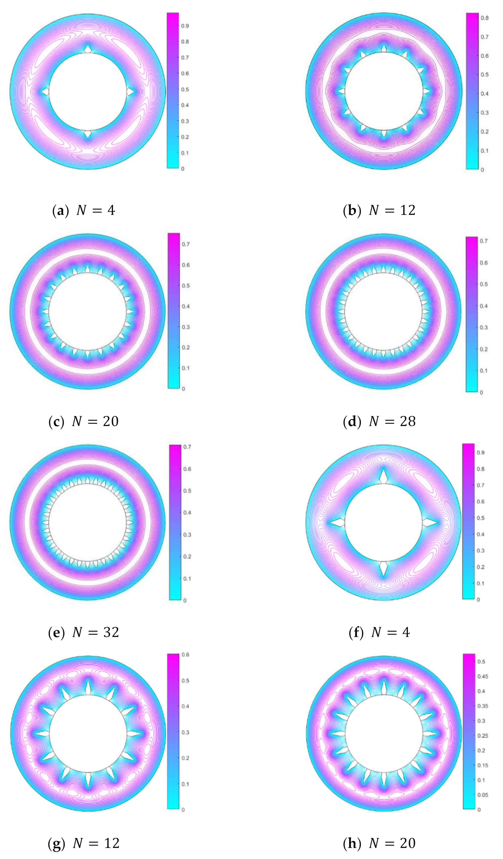
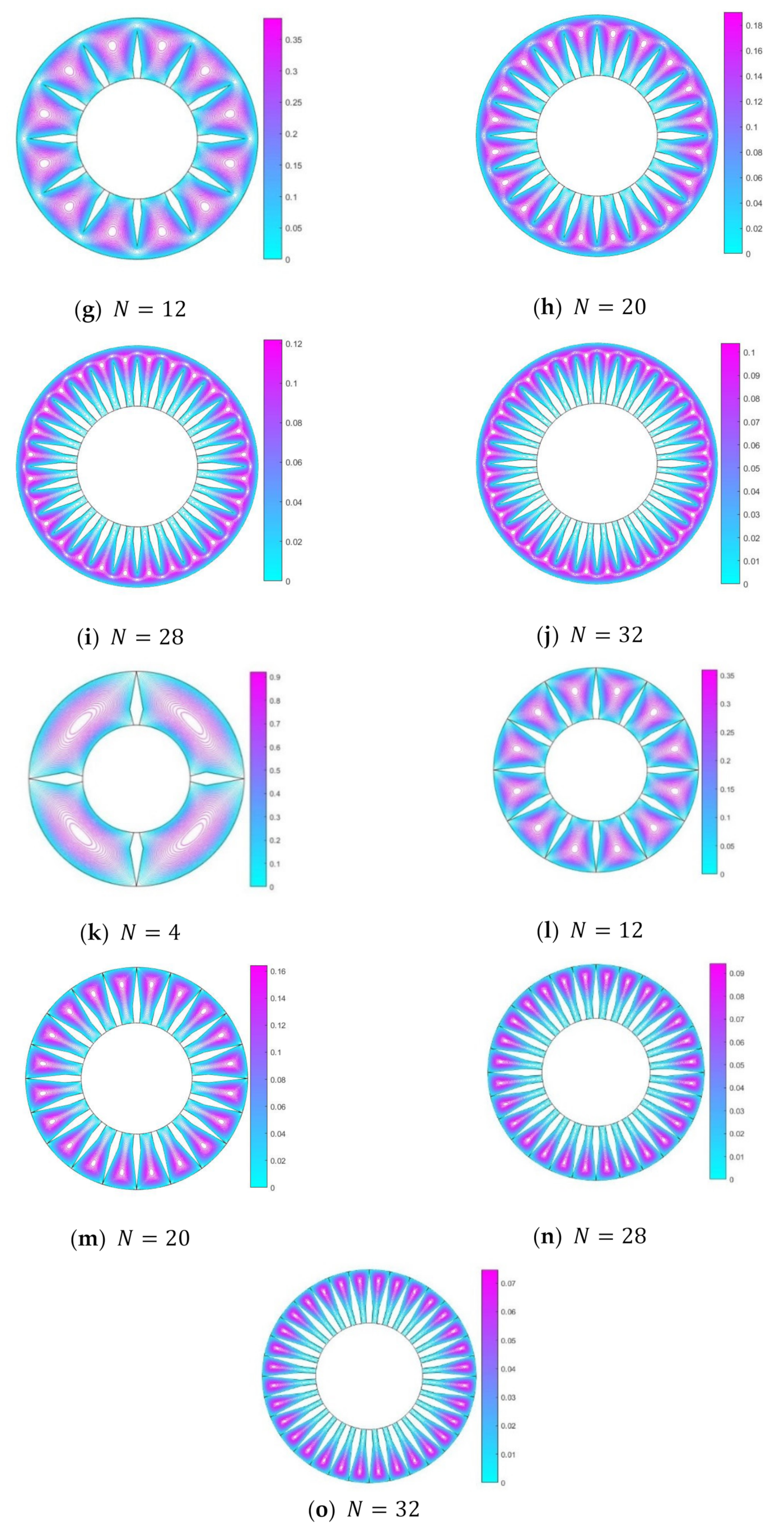
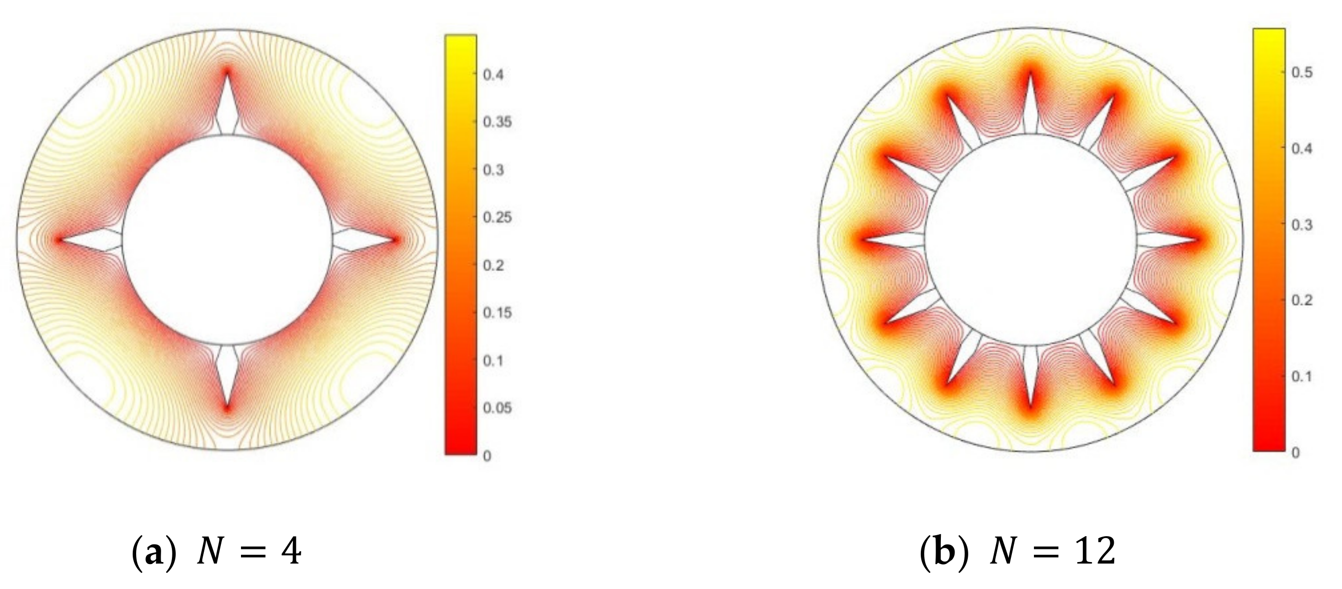
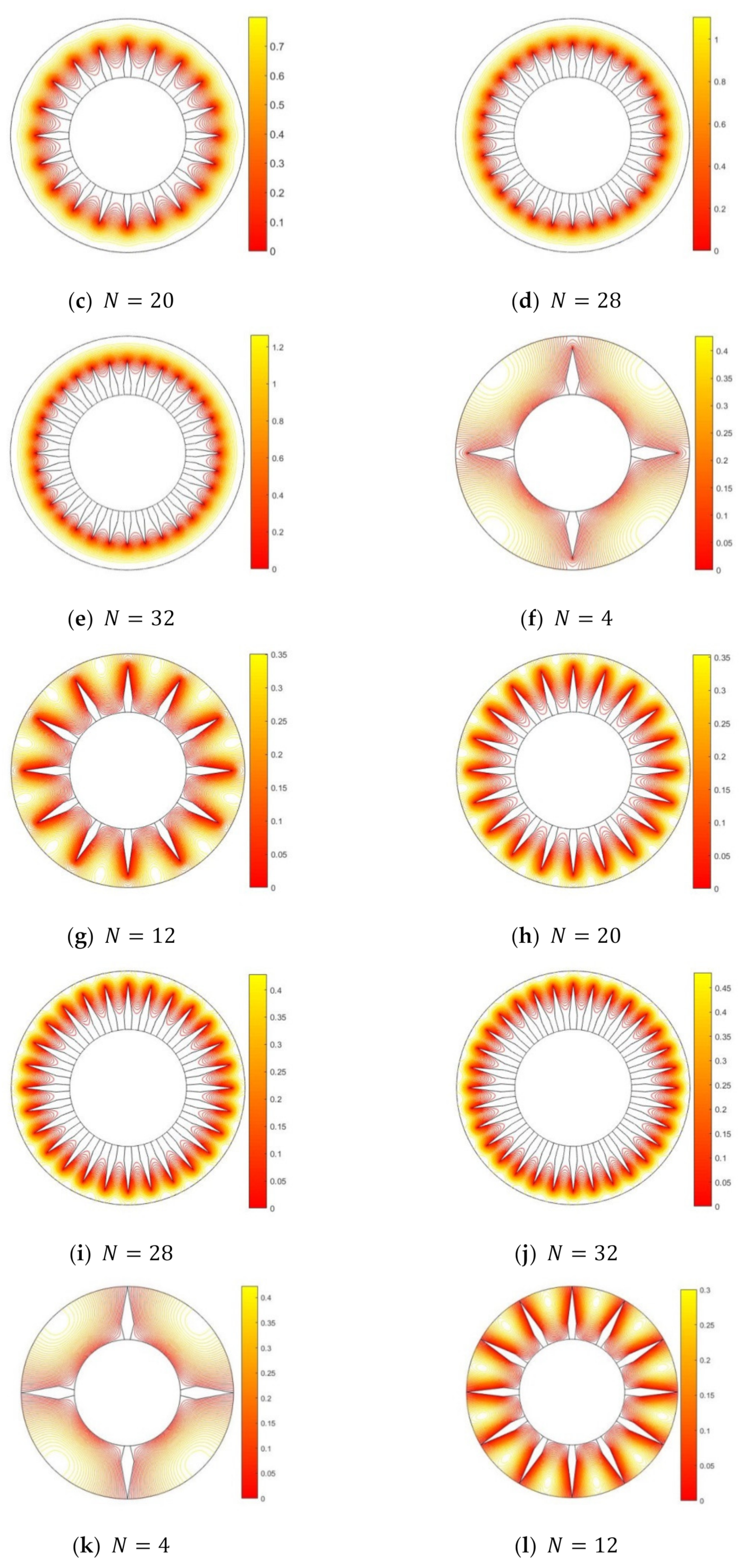
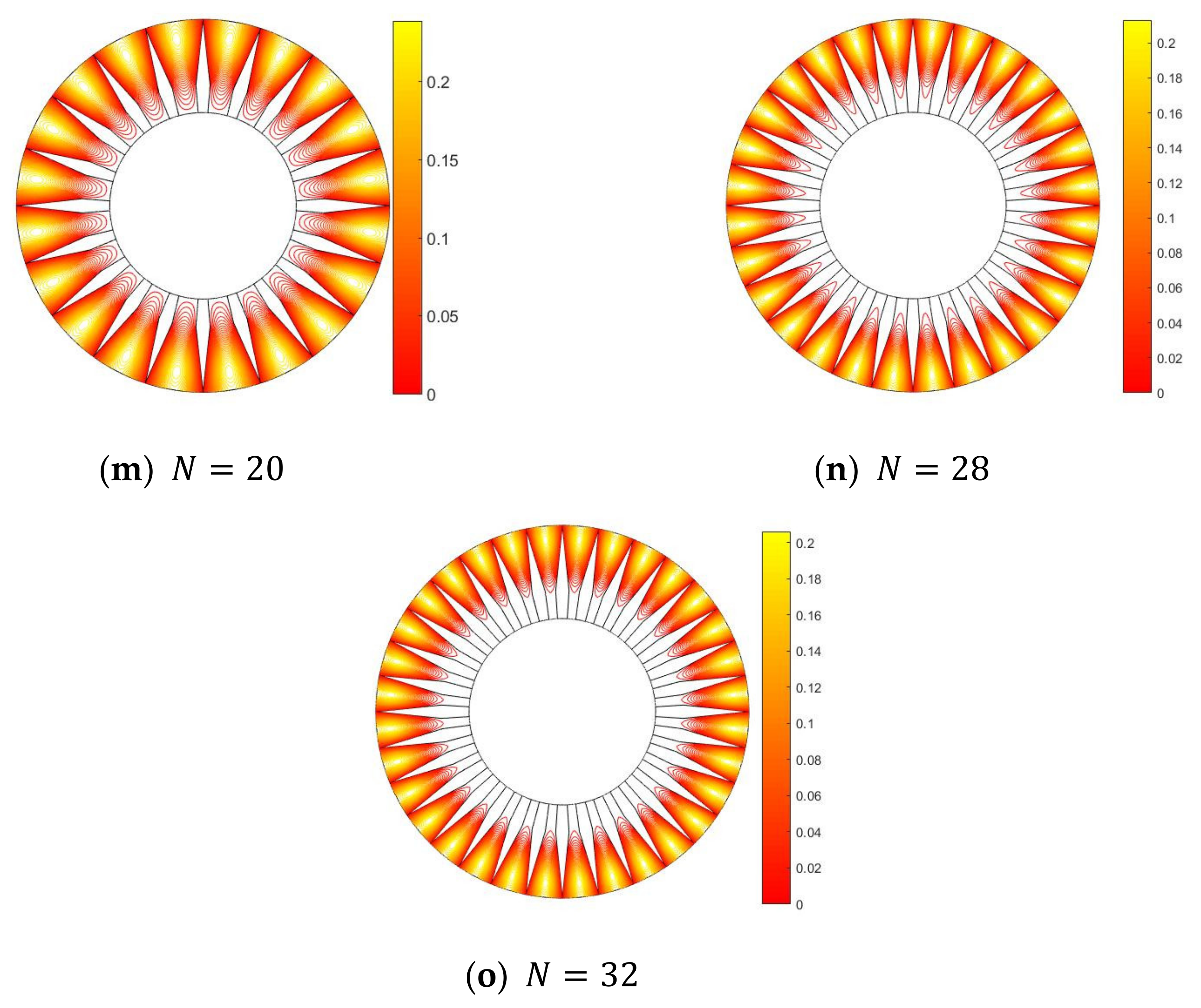
  • Flow analysis suggests that the height and the number of diamond fins play a significant role in the velocity profile.
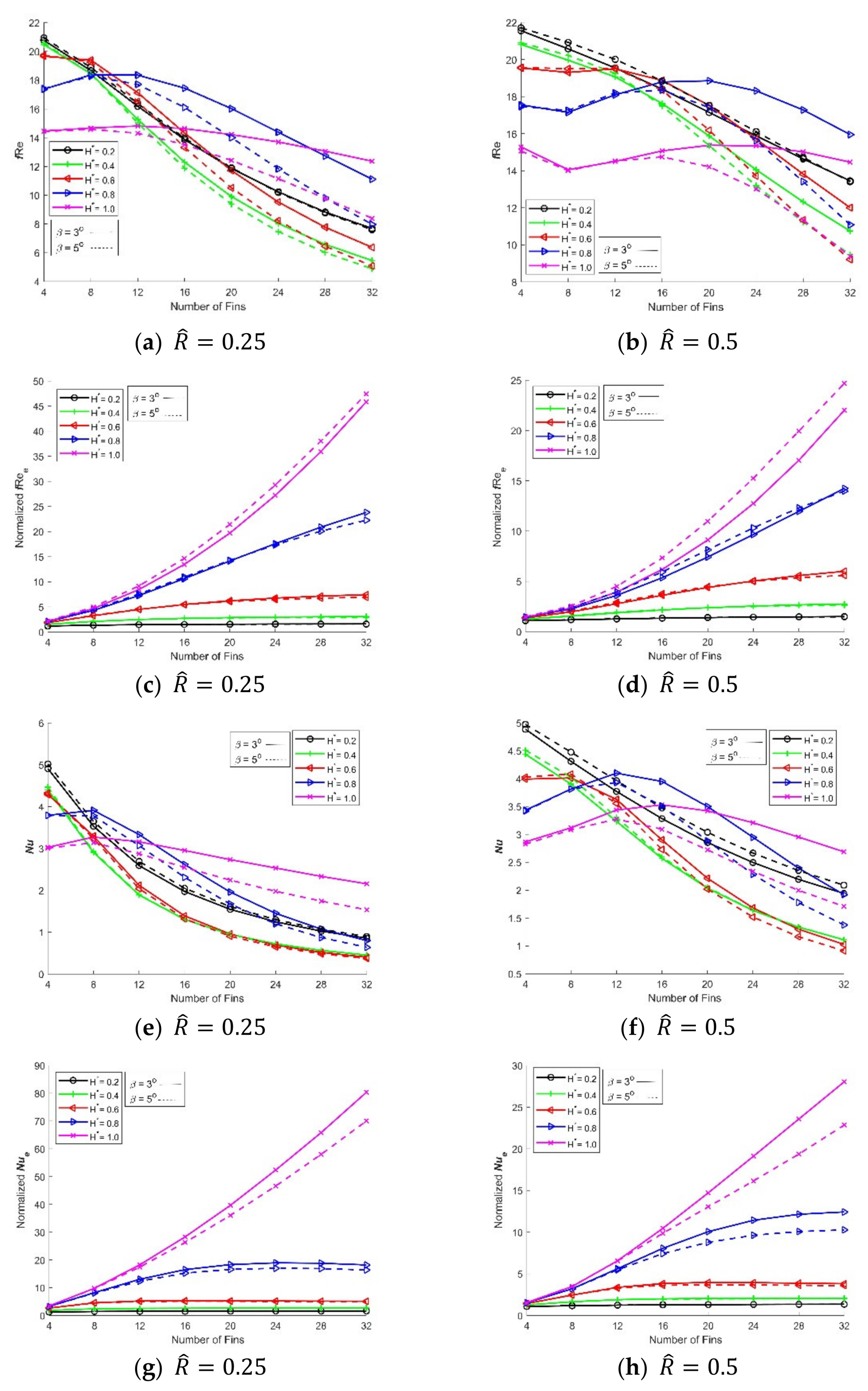
  • The reduction of the pressure drop in the proposed DPHE design depends on the choice of fin thickness, fin-height, radii ratio, and the number of diamond fins.
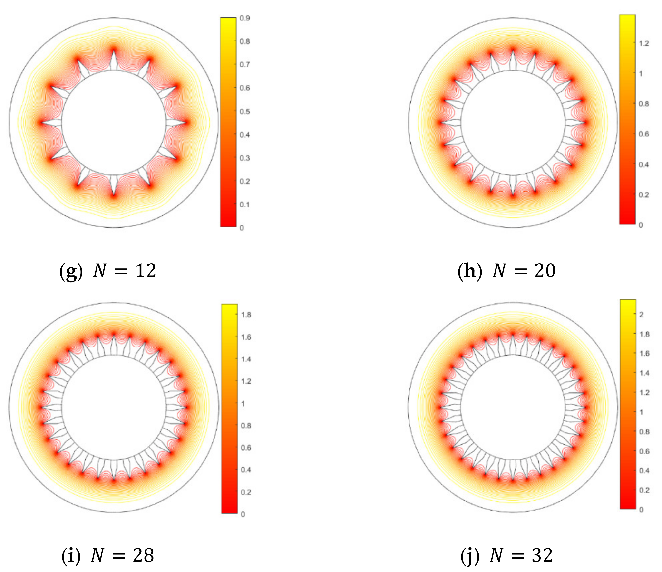
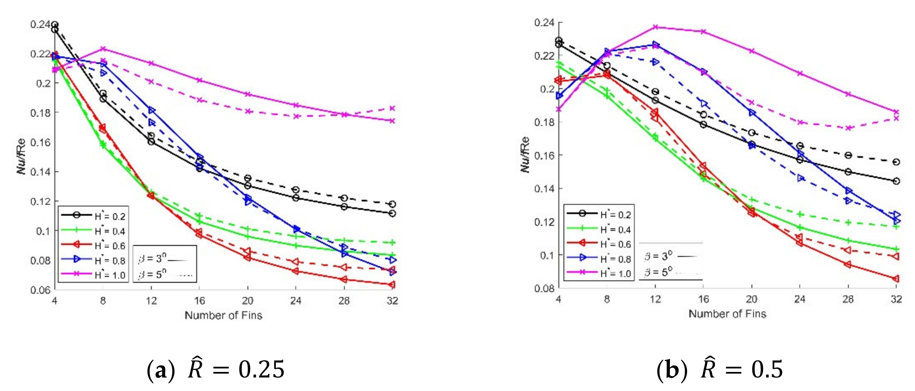
  • Enhanced heat transfer is observed in a DPHE with proposed diamond-shaped fins, at a radii ratio of 0.25 , for the following cases: (i) 4 fins for a fin-height of 20% to 80% of the annulus, (ii) 8–12 fins for a fin-height of 80% of the annulus, and (iii) 16–32 fins for a fin-height of 100% of the annulus.
  • The normalized heat transfer coefficient is greater than unity, showing that the augmentation of the fins increases the coefficient of heat transfer as compared to finless DPHE.
  • The thermal performance of a DPHE with proposed diamond-shaped fins is significantly better in terms of the corresponding rise in the friction factor compared to the finless double pipe. A fin-height of 100 %   of the annulus of DPHE gives the maximum performance for any of the tested choices of the number of diamond fins and radii ratio.
  • Enhanced heat transfer is noted in the DPHE with proposed diamond-shaped fins for the following cases: considering frictional loss, four fins for fin-height varying from 20% to 80% of the annulus, and eight fins for fin-height 100% of the annulus, at a radii ratio of 0.25 .
  • With a change in the radii ratio, the configurations of the diamond-shaped fins in a DPHE may need to be altered to avoid performance decrease.

Author Contributions

Conceptualization, M.I. and A.A.; formal analysis, M.I., M.A., and K.S.S.; investigation, M.I., A.A., M.A., K.S.S., and Z.I.; methodology, M.I., M.A., and K.S.S.; project administration, Z.I.; software, M.I.; supervision, A.A. and Z.I.; validation, A.A., K.S.S., and Z.I.; visualization, M.I. and M.A.; writing—original draft, M.I. and A.A.; writing—review and editing, A.A. and K.S.S. All authors have read and agreed to the published version of the manuscript.

Funding

This research received no external funding.

Institutional Review Board Statement

Not applicable.

Informed Consent Statement

Not applicable.

Conflicts of Interest

The authors declare the following financial interests/personal relationships which may be considered as potential competing interests: Muhammad Ishaq, Amjad Ali, Khalid Saifullah Syed, Zafar Iqbal, and Muhammad Amjad have a patent pending at the Intellectual Property Organization (IPO) Pakistan.

Patents

Muhammad Ishaq, Amjad Ali, Khalid Saifullah Syed, Zafar Iqbal, and Muhammad Amjad have a patent pending at the Intellectual Property Organization (IPO) Pakistan.

Nomenclature

Ac flow cross-sectional area, m2
DHhydraulic diameter of finned geometry, m
fFanning friction factor, dimensionless
jColburn j-factor, dimensionless
Nnumber of fins
Nuaverage Nusselt number, dimensionless
d p d z pressure gradient in finned geometry, pa/m
PrPrandtl number, dimensionless
phheated perimeter, m
Rdimensionless radial coordinate, dimensionless
Re Reynolds number, dimensionless
r ,   , zcylindrical coordinates
riradius of inner pipe, m
roradius of outer pipe, m
Ttemperature, oC
Tbbulk mean fluid temperature, oC
Twfluid temperature at the solid–fluid interface, oC
U*dimensionless axial velocity component, dimensionless
Umaxmaximum axial fluid speed at a cross-section, m/s
θ 1 crown angle (6% of the angle α ) ,rad
α half-angle between successive fins, rad
β fin half angle, rad
k thermal diffusivity, m2/s
λ f thermal conductivity of the fluid, W/m K
τ * dimensionless temperature
h ¯ average heat transfer coefficient, Wm−2K−1
Q ´ heat transfer per unit length, W/m

Subscripts

bbulk
eequivalent diameter
hheated parameter
Hhydraulic diameter
wsolid wall

Superscripts

* dimensionless quantity
overbar (     ¯   ) average value

References

  1. Ozisik, M.N. Heat Transfer: A Basic Approach; McGraw-Hill: Singapore, 1985. [Google Scholar]
  2. Nandakumar, K.; Masliyah, J.H. Fully developed viscous flow in internally finned tubes. Chem. Eng. J. 1975, 10, 113–120. [Google Scholar]
  3. Masliyah, J.H.; Nandakumar, K. Heat transfer in internally finned tubes. J. Heat Transf. 1976, 98, 257–261. [Google Scholar]
  4. Shah, R.K.; London, A.L. Laminar Flow Forced Convection in Ducts; Academic Press: New York, NY, USA, 1978. [Google Scholar]
  5. Soliman, H.M.; Chau, T.S.; Trupp, A.C. Analysis of laminar heat transfer in internally finned tubes with uniform outside wall temperature. J. Heat Transf. 1980, 102, 598–604. [Google Scholar]
  6. Sparrow, E.M.; Charmchi, M. Laminar heat transfer in the externally finned circular tubes. J. Heat Transf. 1980, 102, 605–611. [Google Scholar]
  7. Parakash, C.; Liu, Y.D. Analysis of laminar flow and heat transfer in the entrance region of an internally finned circular duct. J. Heat Transf. 1985, 107, 84–91. [Google Scholar]
  8. Tao, W.Q. Conjugated laminar forced convective heat transfer from internally finned tubes. J. Heat Transf. 1987, 109, 791–795. [Google Scholar]
  9. Agrawal, A.K.; Sengupta, S. Laminar flow and heat transfer in a finned tube annulus. Int. J. Heat Fluid Flow 1990, 11, 54–59. [Google Scholar]
  10. Suryanarayana, N.V.; Apparao, T.V.V.R. Heat transfer augmentation and pumping power in double-pipe heat exchangers. Exp. Therm. Fluid Sci. 1994, 9, 436–444. [Google Scholar]
  11. Syed, K.S. Simulation of Fluid Flow Through a Double-Pipe Heat Exchanger. Ph.D. Thesis, University of Bradford, Bradford, UK, 1997. [Google Scholar]
  12. Yu, B.; Nie, J.H.; Wang, Q.W.; Tao, W.Q. Experimental study on the pressure drop and heat transfer characteristics of tubes with internal wave-like longitudinal fins. Heat Mass Transf. 1999, 35, 65–73. [Google Scholar]
  13. Nasiruddin, M.H.; Siddiqui, K. Heat transfer augmentation in a heat exchanger tube using a baffle. Int. J. Heat Fluid Flow 2007, 28, 318–328. [Google Scholar]
  14. Syed, K.S.; Iqbal, M.; Mir, N.A. Convective heat transfer in the thermal entrance region of finned double-pipe. Heat Mass Transf. 2007, 43, 449–457. [Google Scholar]
  15. Syed, K.S.; Ishaq, M.; Bakhsh, M. Laminar convection in the annulus of a double-pipe with triangular fins. Comput. Fluids 2011, 44, 43–55. [Google Scholar]
  16. Ishaq, M.; Syed, K.S.; Iqbal, Z.; Hassan, A.; Ali, A. DG-FEM based simulation of laminar convection in an annulus with triangular fins of different heights. Int. J. Therm. Sci. 2013, 72, 125–146. [Google Scholar]
  17. Iqbal, Z.; Syed, K.S.; Ishaq, M. Optimal configuration of finned annulus in a double pipe with fully developed laminar flow. Appl. Therm. Eng. 2011, 31, 435–1446. [Google Scholar]
  18. Ishaq, M.; Syed, K.S.; Zafar, I.; Hassan, A. A Conjugate Heat Transfer Analysis of a Triangular Finned Annulus Based on DG-FEM. Math. Probl. Eng. 2018, 2018, 6947565. [Google Scholar]
  19. Arjmandi, H.; Amiri, P.; Pour, M.S. Geometric optimization of a double pipe heat exchanger with combined vortex generator and twisted tape: A CFD and response surface methodology (RSM) study. Therm. Sci. Eng. Prog. 2020, 18, 100514. [Google Scholar]
  20. Maakoul, A.E.; Feddi, K.; Saadeddine, S.; Abdellah, A.B.; Metoui, M.E. Performance enhancement of finned annulus using surface interruptions in double-pipe heat exchangers. Energy Convers. Manag. 2020, 210, 112710. [Google Scholar]
  21. Karoueia, S.S.H.; Ajarostaghi, S.S.M. Influence of a curved conical turbulator on heat transfer augmentation in a helical double-pipe heat exchanger. Heat Transf. 2021, 50, 1872–1894. [Google Scholar]
  22. Dalkılıç, A.S.; Mercan, H.; Özçelik, G.; Wongwises, S. Optimization of the finned double-pipe heat exchanger using nanofluids as working fluids. J. Therm. Anal. Calorim. 2021, 143, 859–878. [Google Scholar]
  23. Luo, C.; Song, K. Thermal performance enhancement of a double-tube heat exchanger with novel twisted annulus formed by counter-twisted oval tubes. Int. J. Therm. Sci. 2021, 164, 106892. [Google Scholar]
  24. Poongavanam, G.; Kim, S.C. Effect of shot peening on augmenting the thermo-fluid characteristic of a concentric tube water-to-air counter flow heat exchanger. Case Stud. Therm. Eng. 2021, 25, 100887. [Google Scholar]
  25. Ali, A.; Khalid, S.S. An outlook of high performance computing infrastructures for scientific computing. Adv. Comput. 2013, 91, 87–118. [Google Scholar]
Figure 1. (a) The double-pipe heat exchanger with extended diamond-shaped fins; (b) Cross-section of DPHE with diamond-shaped fins; (c) numerical domain due to the symmetry.
Applsci 11 05954 g001
Figure 2. Grid independence test: f R e is plotted against the number of triangular mesh for R ^ = 0.5 ,   β = 3 , and N varying from 4 to 32, having 40% height of the annulus. [Colored Figure].
Applsci 11 05954 g002
Figure 3. Dimensionless velocity contours for diamond-finned annulus with number of fins varying from 4 to 32, having 20% (ae) and 40% (fj) height of the annulus and R = 0.5 and β = 3 [Colored Figure].
Applsci 11 05954 g003aApplsci 11 05954 g003b
Figure 4. Dimensionless velocity contours for diamond-finned annulus with number of fins varying from 4 to 32, having 60% (ae), 80% (fj), and 100% (ko) height of the annulus and R ^ = 0.5 and β = 3.
Applsci 11 05954 g004aApplsci 11 05954 g004b
Figure 5. Dimensionless temperature contours for diamond-finned annulus with number of fins varying from 4 to 32, having 20% (ae) and 40% (fj) height of the annulus and R ^ = 0.5 and β = 3.
Applsci 11 05954 g005aApplsci 11 05954 g005b
Figure 6. Dimensionless temperature contours for diamond-finned annulus with number of fins varying from 4 to 32, having 60% (ae), 80% (fj), and 100% (ko) height of the annulus and R ^ = 0.5 and β = 3.
Applsci 11 05954 g006aApplsci 11 05954 g006bApplsci 11 05954 g006c
Figure 7. fRe (ab) and normalized fRe (cd), Nu (ef), normalized Nue (g–h) and normalized j/fe (ij) plotted against the number of fins at R ^ = 0.25, 0.5 and β = 3, 5.
Applsci 11 05954 g007aApplsci 11 05954 g007b
Figure 8. Nusselt number ratio friction factor plotted against the number of fins at β = 3 and 5 .
Applsci 11 05954 g008
Table 1. Comparison of the triangular- and rectangular-finned annulus results for R ^ = 0.5 and   β = 3 .
M l * D h f R e N u ¯ j / f Triangles
40.21.300020.77254.90510.26854315
0.41.138920.47634.39810.24434189
0.61.008719.66194.28890.24813922
0.80.901517.37473.79190.24823783
1.00.811314.46703.02800.23803294
80.21.154718.66483.53090.21512367
0.40.921618.44512.90660.17922319
0.60.760719.39963.29680.19332123
0.80.642618.36733.91050.24211894
1.00.551614.67003.27280.25371783
120.21.037116.18702.59260.18211662
0.40.771415.27311.88990.14071573
0.60.606917.13332.12230.14091461
0.80.494218.35353.33300.20651294
1.00.411614.81603.16010.24261174
160.20.940413.87351.97270.16171323
0.40.661712.30261.30410.12051256
0.60.502214.32441.39040.11041147
0.80.398117.44762.61780.1706951
1.00.324014.63302.95290.2295866
200.20.859611.86391.54700.14831026
0.40.57809.90600.95040.10911000
0.60.426411.71850.95740.0929884
0.80.330816.02401.96030.1391764
1.00.264114.21702.73420.2187644
240.20.791110.23411.24980.1389802
0.40.51208.03710.72210.1022780
0.60.36909.52380.69120.0825739
0.80.281014.38501.45050.1147611
1.00.220513.70502.53390.2103509
280.20.73238.82841.02550.1321753
0.40.45886.57990.56550.0977723
0.60.32407.77130.52030.0761624
0.80.242712.73281.07450.0960535
1.00.187413.06302.33340.2031426
320.20.68127.68800.85810.1269707
0.40.41485.45470.45490.0948647
0.60.28786.37510.40420.0721572
0.80.212311.11900.79980.0818476
1.00.161412.36702.15630.1983358
Table 2. Comparison of the triangular- and rectangular-finned annulus results for R ^ = 0.5 and β = 3 . (* in the superscript represents dimensionless quantity).
Triangular Fin CaseRectangular Fin Case
l * N Present ResultsLiterature [15]
Results
Present ResultsLiterature [11]
Results
f R e N u f R e N u f R e N u f R e N u
0.21220.0713.912520.06913.911819.1533.486419.1253.4833
2416.5632.607516.55042.60614.3192.047414.3022.0466
0.41219.6083.367519.55453.354319.3913.167719.3583.1644
2415.0671.742815.03791.739913.0321.35812.9981.3572
0.61219.9373.845419.90763.831920.0833.937920.0273.9256
2417.2511.927917.18311.917215.8741.421415.8151.4213
0.81218.2824.345418.2514.323517.1974.243617.1454.2311
2419.593.671119.49643.630521.0243.752420.8183.7216
Publisher’s Note: MDPI stays neutral with regard to jurisdictional claims in published maps and institutional affiliations.

