Featured Application
Energy saving hull-form design for a fishing vessel.
Abstract
In response to the increasing number of free trade agreements (FTA) and the Trans-Pacific Partnership (TTP), it is necessary to develop next-generation fishing vessels for the littoral sea of the Republic of Korea. The main objectives of such fishing vessels are to enhance the comfort of the crew and to improve fuel efficiency under the newly established principal dimension. This paper employs the hull form variation method to obtain a series of forebody hull forms of the 19 gross tonnage class of a coastal composite fishing vessel. Chine breadth modification has been used for hull form variations. The objective function is the minimum value of wavemaking resistance. A parametric study was conducted to observe the effects of design parameters on the objective functions, and hull-form optimization was performed. In addition to the hull-form optimization, the effect of the stern flap was investigated in terms of both resistance and operational performances.
1. Introduction
Small fishing vessels, particularly those for the littoral sea, have scarcely been paid attention in terms of design improvement. The small scale and conservatism of the coastal fishing industry are attributable to the lack of incentives for the innovative design of the fishing vessel, thereby subsisting outdated hull-form design with poor performance and obsolete arrangement, which does not take into account crew safety. The coastal fishery, however, is facing multitudes of unprecedented challenges as follows: depletion of fish resources, agreements of the free trade agreements (FTA) and Trans-Pacific Partnership (TPP), deterioration of profitability caused by high fuel prices, proclamation of the Exclusive Economic Zone (EEZ) according to United Nations Convention on the Law of the Sea (UNCLOS), fish-market opening pressure and pollution of the coast, facing the World Trade Organization (WTO), etc.
In response to these environmental changes, some of the advanced countries in the fishery industry have devoted themselves to restructuring the industry toward a safer working environment and cost-effectiveness. The fishery registration in the Republic of Korea is based on the gross tonnage (G/T) of the vessel, whereas in Europe, it is based on the length () of the vessel. The G/T basis registration system in the Republic of Korea has led to vessel design with a longer length () and shallow depth () to satisfy the G/T limit, which may deteriorate the stability of the vessel significantly. In addition, the displacement of the vessel is preferentially allocated to the fish tank with living quarters for crews being sacrificed. The European length basis registration system, however, is to set the maximum allowable length for the vessel class without limiting the G/T, which contributes to lowering the length to beam ratio (). This will certainly help to enlarge living quarters for crews, thereby enhancing crew comfort and safety. This is the reason why the length basis registration system is being legislated in the Republic of Korea. The next generation Korean fishing vessel development program aims at developing new hull forms for 10 different kinds of coastal and littoral fishing vessels. Generally speaking, the lowered ratio expected under the new regulatory system will lead to an increase in resistance and fuel consumption. Therefore, more efficient hull forms and appendage designs are to be developed in the program.
Most small fishing vessels are designed after the semi-displacement type hull form, which has hard chine with V-shaped sections in the forebody and flat sections in the afterbody. This is because the semi-displacement type hull is superior to the displacement type hull in terms of stability, operation performances, and construction cost. The V-shaped sections provide a fine entry and prevent the vessel from pounding in a seaway. The flow traveling along the hull creates significant form stability, which prevents the rolling motion. The flat hull sections in the afterbody provide hydrodynamic lift and allow the vessel to run at acceptable speeds for both empty and fully loaded conditions. A fishing vessel is supposed to move toward the fishing grounds at a higher speed with an empty fish tank and return at a slower speed with a loaded fish tank.
Since the study on the hull form of a trawler by Doust [1], the hull forms of the fishing vessels have been slowly improving. The Korean Institute of Machinery and Materials [2] designed and announced 13 coastal FRP fishing vessels. In 1994, the Korean Fishing Vessel Society developed and announced 60 standard fishing vessels [3]. Those announced designs have been utilized as the standard hull forms for Korean domestic fishing vessels. Several studies have been reported to improve the standard hull forms: G/T 2.99 ton class fishing vessel [4]; G/T 4.99 ton class [5]; G/T 29 ton class [6]; G/T 199 ton class [7]. As the class names imply, these previous studies all remained within the G/T basis registration system, which is now under reform.
A closer inspection of the literature survey reveals the relevant direction of hull form improvement for small coastal fishing vessels. Kim et al. [8] addressed the effectiveness of increasing stern overhang, proper initial trimming, and maintaining chain breadth at the bow region. Kang et al. [5] and Yu and Lee [9] identified relevant nondimensional design parameters such as , , and (: length of waterline, : volume displacement, : chine breadth, : mean draft, : prismatic coefficient, : longitudinal center of buoyancy). The effective power of fishing vessels could be expressed by means of a regression formula in terms of those nondimensional parameters, whose optimal combination could lead to the minimization of effective power. Once the optimal combination of length (), breadth (), and draft () is determined, then the optimal hull form can be obtained by simply stretching or contracting the initial, parent hull form using the Lackenby method. Jee et al. [10] noted that the gradient of the chine line is more important than other parameters of the keel shape and stern length in reducing the resistance. Kim et al. (2017) reduced the resistance through the parametric study in which bow shoulder, sectional area curve (SAC), frame shape, and center skeg were varied.
High-speed vessels change their hydrodynamic properties due to large changes in running attitude above a certain speed. Potential flow solvers can be used to estimate running attitude, but they are not efficient for high-speed vessels with large trim changes. The present study intends to develop the optimal hull form for G/T 19 ton class coastal composite fishing vessel for the next generation Korean fishing vessel development program. A parametric study based on CFD viscous flow simulation was performed to optimize such design parameters as the chine breadth and the deadrise angle. CFD used the commercial code STAR-CCM+. The computation was performed by considering dynamic trims and free surfaces on the model scale. In addition, the stern appendage to improve running trim was also employed to further reduce the resistance of the optimal hull form.
2. Objective Ship
The coastal fishing vessels are in the range of 8-10 G/T, which is based on the gross tonnage registration, and classified into eight types; coastal stow nets, coastal purse seine, coastal trap, eastern sea trawl, coastal drag nets, coastal drift gill nets, coastal lift nets, and coastal composite. The coastal composite fishing vessel was selected as the objective ship type in this study, because this is the most abundant coastal ship type occupying more than half of all domestic coastal fishing vessels [11].
The objective ship was a G/T 19 ton class coastal composite fishing vessel, which is based on the L registration. The initial hull form was designed by the Research Institute of Medium and Small Shipbuilding (RIMS). The principal dimensions at sea trial condition are listed in Table 1. The design speed () is 16.00 knots. The corresponding Froude number () is 0.645, which is defined by and . The body plan and side view of the initial hull are presented in Figure 1. Note that the vessel is initially trimmed to stern by 1.9o at sea trial condition ( m and m). The dashed line denotes the chine line. The hull form features the characteristics of a ‘semi-displacement hull’, which has a hard chine with a deep V-shaped section type (forebody) and flat type (afterbody). Having both features of a displacement hull and a planning hull, the semi-displacement hull is capable of maintaining high efficiency for both low and high speeds. The chine line is immersed below the waterline from St. 15.3 to the stern. The chine breadth () is constant from midship to stern.

Table 1.
Principal particulars of the initial hull form at the sea trial condition.
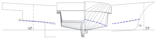
Figure 1.
Body plan and side view of the initial hull form of the objective ship.
3. Computational Method
3.1. CFD
The vessel is advancing at a constant mean forward speed in calm water. The vessel fixed right-handed global coordinate system () is defined as positive in the flow direction, positive in the starboard, and positive upward. The origin is located at the intersection point of the midship plane, the centerplane, and the undisturbed free surface. Note that sinkage to downward and trim by bow are defined to be negative.
3.1.1. Governing Equations
The governing equations for the viscous-flow solver are the continuity equation and two-phase unsteady Reynolds Averaged Navier–Stokes (RANS) equations. A realizable k-ε model was employed for the turbulent closure. The free surface is obtained by solving a volume of fluids (VOF) equation.
3.1.2. Computational Methods
To solve the governing equations, the flow domain was subdivided into a finite number of cells, and the equations are changed into algebraic form via the discretization process. The cell-centered finite volume method was used for the space discretization. The second-order upwind scheme and the central difference scheme were used to discretize the convective terms and the diffusion terms, respectively. The semi-implicit method for the pressure-linked equations (SIMPLE) algorithm was applied to the velocity–pressure coupling. The temporal discretization was the second-order Adams–Bashforth scheme. A high-resolution interface-capturing scheme was employed to compute the evolution of the free surface by solving the VOF equation.
3.1.3. Computational Domain and Boundary Conditions
The computational domain and boundary conditions are presented in Figure 2. The computational domain is a rectangular shape defined for , and . Undisturbed free surface was set at such that water was filled for and air being for initially. A numerical damping zone was applied in the region of to ensure no wave reflection at the boundaries of the solution domain. The symmetry of the hull form about the centerplane allowed half domain simulation. The no-slip condition was applied on the hull surface, with the standard wall function being utilized to compute turbulence quantities. Velocity inlet and pressure outlet boundary conditions were applied for the inlet and outlet boundary plane, respectively. Symmetry condition was applied on the symmetry and the side boundary plane. The slip wall boundary condition was applied on the top and bottom boundary plane, referring to Lee et al. [12].
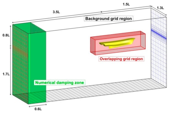
Figure 2.
Computational domain and boundary conditions.
3.1.4. Grid Generation
The overset grid systems were applied, in which the overlapping grids moved with the ship motion, which was calculated by solving heave and pitch motion based on vertical force and moment equilibrium. The grids were generated using STAR-CCM+ by means of the trimmed mesh approach. A five-element prismatic layer was generated near the wall to resolve the boundary layer. The position of the 1st grid from the hull surface was set at . The computational grid for the medium mesh system is presented in Figure 3. The number of mesh is about 1.89 million. Fine grids were deployed to resolve the free surface accurately.
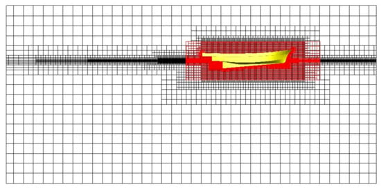
Figure 3.
Computational grid of overlapping and background region (medium mesh).
3.2. Validation and Verification of CFD Results
The computational results are validated through comparison with experimental results. A scaled model test was conducted at Pusan National University’s towing tank to evaluate the resistance performance of the initial hull form [13]. The model–ship scale ratio was set to be 7.0. The design speed for the model based on the Froude similarity scaling was set as m/s. Here, the subscript S and M refer to the ship and model scale, respectively.
Figure 4 displays the total resistance coefficient () and residuary resistance coefficients () of the initial hull form obtained from the model test. The was calculated based on the 2-D analysis method . The continuously increases up to ( knots), which is typical behavior for a displacement ship. Beyond , continues to decrease with increasing , which is consistent with the behavior of a planning vessel. In other words, this result indicates that the initial hull form represents the features of the semi-displacement vessel. At the design speed (, knots), the takes up approximately 77% of the , which is a considerable portion. Since is closely associated with the wavemaking resistance and viscous pressure resistance, the efficient hull-form design should focus on reducing those resistance components. The former part can be reduced by bow hull-form design, while the latter is controllable by appropriate stern appendage. It is worthwhile to mention that these two approaches are employed in the present study.
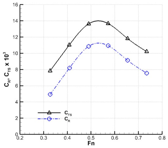
Figure 4.
Total resistance coefficient and residuary resistance coefficient obtained from the model test.
The total resistance of model at design speed predicted by CFD is compared with that measured in the model test in Table 2. To ensure mesh independency, three different grids are created and simulated for the initial hull. Considering the results and computation time of numerical simulation, the medium mesh is selected as the basic grid system. The error between is only 1.6%, which corroborates the reliability of the present CFD prediction. In addition, the trim and sinkage values predicted by CFD are in close agreement with those values measured by the model test.
Table 2.
Model test and CFD results of the initial hull form at design speed.
4. Results
4.1. Bow Hull form Variation
The objective function is to minimize the wavemaking resistance in calm water () at the design speed. The equality constraints are the principal dimensions of , , (, , ), and . Two design variables of chine breadth increment ratio () and deadrise angle () are taken into account. The chine breadth increment ratio is the independent variable and defined as the nondimensional increment ratio between of the varied hull form and that of the initial hull form, i.e., . can vary along the longitudinal position of the ship, attaining a maximum value of at the midship. The deadrise angle is a dependent variable and defined as the angle between the horizontal plane and the hull bottom. In order to satisfy the displacement constraint, has been adjusted for each value. The design variable and are displayed in Figure 5.
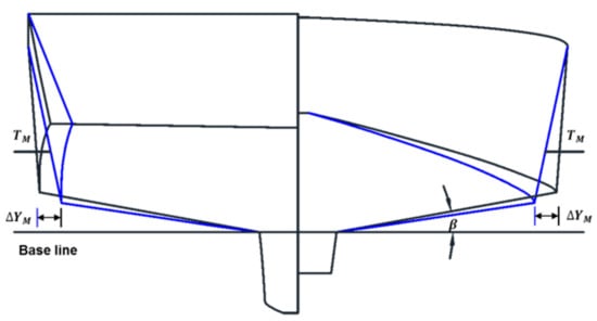
Figure 5.
Design variables for hull form variation.
Among other design variables, has a significant influence on the resistance performance of fishing vessels with chine lines [14,15]. Since the chine breadth mainly affects the wavemaking resistance, it is varied only in the forebody in this study. In other words, increases linearly from zero to in the forebody, maintaining throughout in the afterbody. Figure 6 illustrates five different hull forms with varying . Note that corresponds to the initial hull form. Further, the case becomes the maximum allowable increment for which the chine breadth becomes equal to the mold breadth .
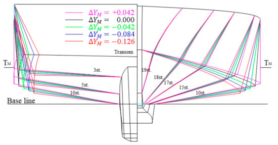
Figure 6.
Comparison of initial and varied hull forms.
Figure 7a presents the ratio of total resistance () in model scale predicted at the design speed with varying . Here, corresponds to the total resistance of the initial hull form (). Note that the values of are compared instead of resistance coefficient . This is because the wetted surface area varies for each hull form variation. It is observed that decreases for negative values of , i.e., for narrower chine breadths. In particular, maximum resistance reduction by 2.36% occurs at , which is considered to be the optimal value.
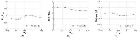
Figure 7.
Variation of total resistance, trim, and sinkage depending on design parameter . (a) Ratio of total resistance; (b) Trim; (c) Sinkage.
Variation of trim and sinkage are plotted against in Figure 7b,c, respectively. For a relatively small change in the chine breadth (), the trim and the sinkage do not change appreciably. On the contrary, both change significantly for a larger change in the chine breadth corresponding to . In this region, the hull sinks less, and the trims more to the stern. The trim angle for the optimal becomes approximately 4°. This large trim angle may cause a serious safety issue due to the limited forward visibility. Therefore, a second measure to decrease the excessive trim angle without deteriorating the resistance performance, which will be discussed in the next section.
Wave patterns and pressure distributions of the initial and optimal hull form at design speed are compared in Figure 8. The optimal hull form shows a significant decrease in the bow wave, and the stern shoulder wave is also found to decrease slightly. In addition, the significant reduction in the positive pressure peak in the bow region is attributable to the change in the running attitude, i.e., the increase in stern trim and the decrease in sinkage.
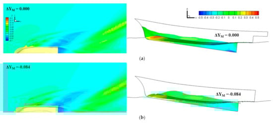
Figure 8.
Comparison of wave pattern and pressure distribution of the initial and optimum hull form at design speed. (a) Initial hull (); (b) optimal hull ( ).
For a newly developed hull form for a small fishing vessel, the transverse stability should also be taken into consideration. Kwon and Lee [16] proposed a stability criteria for small fishing vessels
This formula gives the minimum required value for the metacentric height to be 1.075m. Table 3 lists the transverse metacenter (), center of gravity (), and of the initial and varied hull forms. It appears that all hull forms have the metacentric height values exceeding the minimum required value, thereby satisfying the stability criteria.
Table 3.
The metacentric height of initial and varied hull forms.
4.2. Effect of Stern Appendage
The running attitude of a high-speed vessel is one of the major factors affecting the resistance performance. In case of excessive stern trim, attaching stern appendage to build lift can reduce the resistance by 3 to 10% by reducing the stern trim by 1° to 3° [17]. In the previous study by the authors [13], the stern flap was adopted as the stern appendage to improve the resistance performance of the initial hull. The design variables for the stern flap are shown in Figure 9, the ratio of chord length to , and the flap angle .
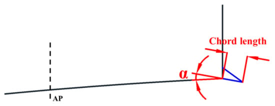
Figure 9.
Definition of the design parameters of the stern flap.
Having carried out a series of model tests, Lee et al. [13] found out the optimal parameter to be and . This design of stern flap was employed for the hull forms considered in this study as well. In this study, the effect of the stern flap on the resistance and running attitude was predicted by CFD simulation.
Figure 10 compares the resistance ratio, trim, and sinkage between hull forms with and without stern flap. It is clear that the stern flap leads to the reduction of the stern trim for all hull forms, as shown in Figure 10b. However, the stern flap affects the resistance and the sinkage differently, depending on hull forms. For instance, the stern flap did not lead to further resistance reduction for the optimal hull form ().
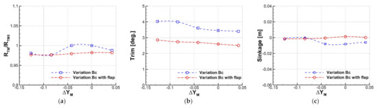
Figure 10.
Variation of total resistance, trim, and sinkage depending on design parameter and stern flap. (a) Ratio of total resistance; (b) trim; (c) sinkage.
Wave patterns and pressure distributions of the optimal hull form with and without flap at the design speed are compared in Figure 11. For the optimal hull form, the attachment of the stern flap weakened the stern wave as a whole. However, this effect was counteracted by the amplified bow waves, thereby making little resistance changes overall. This is shown in the wave profile near the hull surface with the pressure distribution in Figure 11. The effects from hull-form optimization and the stern appendage optimization cannot necessarily be superposed because both are related to nonlinear flow physics. The stern flap is still advantageous for the sake of safety by reducing excessive stern trim angle down to 2.74°.
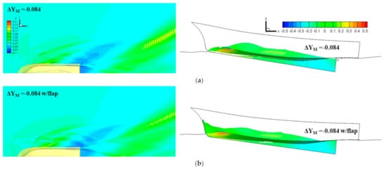
Figure 11.
Comparison of wave pattern and pressure distribution of the optimal hull form with and without stern flap. (a) Optimal hull () without stern flap; (b) optimal hull ( ) with stern flap.
5. Conclusions
A parametric study on the modification of section geometry was performed to develop an optimal hull form for a fishing vessel. By varying chine breadth and deadrise angle under the constant displacement constraint, a series of hull forms for coastal composite fishing vessels was generated, and their resistance performances were evaluated via CFD simulation. For the optimal hull, the total resistance is found to be reduced by 2.36%. Attaching the stern flap to the optimal hull form did not lead to additional resistance reduction. However, the stern flap contributes to enhancing operational performance and safety by reducing excessive stern trim.
Author Contributions
Conceptualization, S.-B.S. and I.L.; methodology, Y.-I.K.; software, M.-K.L.; validation, S.-B.S.; formal analysis, J.-W.Y.; investigation, J.-W.Y.; resources, M.-K.L.; data curation, J.-W.Y.; writing—original draft preparation, J.-W.Y.; writing—review and editing, I.L.; visualization, Y.-I.K.; supervision, I.L.; project administration, I.L.; funding acquisition, I.L. All authors have read and agreed to the published version of the manuscript.
Funding
This work was funded by the Ministry of Oceans and Fishery (MOF, Korea) through the Next Generation Korea-model Fishing Vessel Development and Test-bed Application program (Grant No. 20170255) and the Ministry of Trade, Industry, and Energy (MOTIE, Korea) through the Development of Core Industrial Technology Program (Grant No. 10076439).
Institutional Review Board Statement
Not applicable.
Informed Consent Statement
Not applicable.
Conflicts of Interest
The authors declare no conflict of interest.
References
- Doust, D.J. Trawler Forms with Bulbous Bows. In Fishing Boats of the World: 2—Sea Behavior; Fishing News Ltd.: London, UK, 1960; pp. 445–452. [Google Scholar]
- Korea Institute of Machinery and Materials. Research on the Modernization of Small Fishing Boats; KIMM: Daejon, Korea, 1984. (In Korean) [Google Scholar]
- Korea Fishing Vessel Society. Report on the Development of Standard Fishing Vessels; KFVS: Seoul, Korea, 1994. (In Korean) [Google Scholar]
- Kim, I.S.; Go, D.G.; Park, D.W. A study on hull dorm design for small fishing vessels. J. Korean Soc. Mar. Eng. 2017, 41, 316–322. (In Korean) [Google Scholar]
- Kang, D.S.; Yu, J.W.; Lee, Y.G. A Study on the Hull Form Design with Minimum Resistance for Domestic Coastal Fishing Boats. J. Soc. Nav. Arch. Korea 2007, 44, 349–359. (In Korean) [Google Scholar] [CrossRef][Green Version]
- Ha, Y.J.; Lee, Y.G.; Lee, S.H.; Kim, S.H.; Yu, J.W.; Back, Y.S.; Bae, D.G. Improvement of the Resistance Performance for a G/T 29ton Class Coastal Angling Fishing Boat based on Hull-form Design. J. Soc. Nav. Arch. Korea 2014, 51, 521–529. (In Korean) [Google Scholar] [CrossRef][Green Version]
- Park, A.S.; Lee, Y.G.; Kim, D.D.; Yu, J.W.; Ha, Y.J.; Jin, S.H. A Study on the Resistance Reduction of G/T 190ton Class Main Vessel In Korean Large Purse Seiner Fishing System. J. Soc. Nav. Arch. Korea 2012, 49, 367–375. (In Korean) [Google Scholar] [CrossRef]
- Kim, D.J.; Park, J.W.; Kim, J.N.; Jeong, U.C. An experimental study on the resistance performance of small size fishing vessel. Bull. Korean Soc. Fish. Technol. 2004, 40, 304–310. (In Korean) [Google Scholar]
- Yu, J.W.; Lee, Y.G. A Study on the Bow Wave Characteristics for the Resistance-Minimized Hull Form of Small Fishing Boat. J. Soc. Nav. Arch. Korea 2008, 45, 124–131. (In Korean) [Google Scholar] [CrossRef]
- Jee, H.W.; Lee, Y.G.; Kang, D.S.; Ha, Y.J.; Choi, Y.C.; Yu, J.W. Resistance Performance of Korean Small Coastal Fishing Boat in Low-Speed Range. J. Soc. Nav. Arch. Korea 2009, 46, 10–23. (In Korean) [Google Scholar] [CrossRef]
- Yoon, S.C.; Jeong, Y.K.; Zhag, C.I.; Yang, J.H.; Choi, K.H.; Lee, D.W. Characteristics of Korean Coastal Fisherises. Korean J. Fish. Aquat. Sci. 2014, 47, 1037–1054. (In Korean) [Google Scholar]
- Lee, C.M.; Yu, J.W.; Choi, J.E.; Lee, I. Effect of bow hull forms on the resistance performance in calm water and waves for 66k DWT bulk carrier. Int. J. Nav. Archit. Ocean Eng. 2019, 11, 723–735. [Google Scholar] [CrossRef]
- Lee, M.K.; Kim, S.J.; Yu, J.W.; Lee, I. An Experimental Study on the Optimization of Stern Appendix for New Generation Korean Fishing Vessels. J. Soc. Nav. Arch. Korea 2021, 58, 32–39. (In Korean) [Google Scholar] [CrossRef]
- Tsuchiya, T. New Statistical Regression Analysis for Fishing Boat Hull Resistance. J. Soc. Nav. Arch. Jpn. 1972, 132, 63–80. [Google Scholar] [CrossRef]
- Lee, Y.G.; Yu, J.W.; Kim, K.S.; Kang, D.S. A Study on the Effective Horsepower Estimation for Domestic Coastal Fishing Vessels. J. Soc. Nav. Arch. Korea 2006, 43, 313–321. (In Korean) [Google Scholar]
- Kwon, S.Y.; Lee, H.J. A Study on the Stability Criterial of Small Vessels. J. Soc. Nav. Arch. Korea 2007, 44, 285–295. (In Korean) [Google Scholar] [CrossRef]
- Seo, K.H.; Lee, J.K.; Seo, Y.N.; Sun, J.H.; Heo, J.K. A Review on Hull Designs and Appendages Performances for Development of a 60m Class Semi-planing Craft. In Proceedings of Fall Annual Meeting of SNAK; SNAK: Yongin, Korea, 2005; pp. 869–875. (In Korean). [Google Scholar]


Publisher’s Note: MDPI stays neutral with regard to jurisdictional claims in published maps and institutional affiliations. |
© 2021 by the authors. Licensee MDPI, Basel, Switzerland. This article is an open access article distributed under the terms and conditions of the Creative Commons Attribution (CC BY) license (https://creativecommons.org/licenses/by/4.0/).