Article

Experimental/Numerical Acoustic Assessment of Aircraft Seat Headrests Based on Electrospun Mats

1
Department of Industrial Engineering, University of Salerno, Via Giovanni Paolo II 132, 84084 Fisciano, Italy
2
Siemens Industry Software, Simulation and Test Solutions, Interleuvenlaan 68, B-3001 Leuven, Belgium
3
Italian Aerospace Research Centre (C.I.R.A.), Via Maiorise snc, 81043 Capua, Italy
*
Author to whom correspondence should be addressed.
Appl. Sci. 2021, 11(14), 6400; https://doi.org/10.3390/app11146400
Submission received: 4 June 2021 / Revised: 7 July 2021 / Accepted: 9 July 2021 / Published: 11 July 2021

Abstract

:
The work proposes a methodology for the assessment of the performances of Passive Noise Control (PNC) for passenger aircraft headrests with the aim of enhancing acoustic comfort. Two PNC improvements of headrests were designed to reduce the Sound Pressure Level (SPL) at the passengers’ ears in an aircraft cabin during flight; the first was based on the optimization of the headrest shape, whereas the second consisted of partially or fully covering the headrest surface with a new highly sound-absorbing nanofibrous textile. An experimental validation campaign was conducted in a semi-anechoic chamber. A dummy headrest was assembled in different configurations of shape and materials to assess the acoustic performances associated to each set up. In parallel, simulations based on the Boundary Element Method (BEM) were performed for each configuration and an acceptable correlation between experimental and numerical results was obtained. Based on these findings, general guidelines were proposed for the acoustical design of advanced headrests.

1. Introduction

Acoustic computation and noise prediction, accounting for its generation and transmission, is a challenging task with several applications in different industrial sectors. A concern of increasing interest in the aerospace and automotive industries is the acoustic comfort of passengers [1], thus highlighting the need for noise prediction at early design stages. Indeed, noise or, more generally, unwanted sound, has become a growing problem for human health, leading to several adverse effects, including hearing loss, cardiovascular problems, sleep disturbance and psychological harms [2,3]. The accurate evaluation of noise generation and propagation is nowadays a key concern, especially in the areas in which the comfort of end users has become a turning point.
The focus of the present work is the mitigation of noise inside vehicle cabins, in particular in the case of aircraft fuselages. Several classical deterministic and statistical approaches exist for the prediction and analysis of noise in such scenarios, and each of them bears advantages and limitations. For instance, deterministic methods such as multibody simulation [4], Finite Element Method (FEM) [5], Boundary Element Method (BEM) [6] but also hybrid methods [7,8] are computationally expensive due to geometrical complexity and inherent frequency limitations. As a matter of fact, owing to the large dimensions of aeronautical structures, accurate acoustical computations in the range of human hearing often require the resolution of hundreds of natural frequencies. As a result, reduced approaches [9] and algorithms to lighten the computational requirements [10] often become mandatory. Finally, Statistical Energy Analysis (SEA) can be preferable at higher frequencies for which deterministic approaches are no longer viable due to the high modal densities [11].
In the field of linear acoustics, the BEM is a suitable alternative to FEM and stands as a good compromise between the frequency range of applicability and the prediction of deterministic complex quantities. This is especially true for exterior problems, where the acoustic domain can be modeled as infinite in extent. Applying domain discretization methods such as FEM to such a problem clearly requires careful thought (an example of the infinite radiation condition application with FEM is available in [12]). Instead, it is more advantageous to use the BEM for this kind of application, since only the surface mesh of the vibrating/scattering bodies is required, as the Sommerfeld radiation condition is naturally satisfied at infinity [13]. In this way, both preprocessing times and runtimes can be reduced.
In the last decades, BEM has become an established computational method for acoustics, widely adopted for noise calculations in the low and mid frequency range [14]. To solve small to mid-sized scattering, radiation, or coupled problems, the use of a direct BEM solver is recommended as, in comparison with the iterative solver, it will be more accurate and not limited by possible convergence issues. The main limitation to the size of the problem related to the direct BEM solver is in terms of memory to store and to invert the BEM matrices (full and complex).
Aeronautical applications require the use of lightweight structures and low-energy consumption. Despite the advent of active noise cancellation in aircraft [15,16], passive noise control by means of lightweight sound-absorbing materials remains a viable solution [17]. Within the field of these absorbing materials, nanofibers have recently attracted great attention for sound absorption [18,19]. The thin fiber diameter (less than a micrometer) gives a high surface-to-volume ratio, which is an ideal property for lightweight and porous materials. When a layer of nanofibers is exposed to incident sound waves, the viscous and thermal dissipation inside the nano-pores, and the scattering of waves interacting with fibers, dissipate the sound energy. Furthermore, the nanofiber layers act as an acoustic resonance membrane: the nanofibrous membrane resonates at given frequencies, consequently increasing the rate of sound energy conversion into thermal energy.
Because of these characteristics and thanks to recent advances in the field of nanotechnology and the introduction of different types of nanomaterials, nanofiber-based sound absorbers are considered a promising solution, especially for aeronautic and automotive applications in which noise reduction requirements in new products are becoming more and more strict. In light of this trend, research effort is devoted to the experimental assessment of the sound absorption properties of nanofiber layers [20,21,22].
Reducing in-cabin noise can be achieved by using high performance materials in combination with advanced computational approaches to evaluate upfront the performances of several PNC (Passive Noise Control) implementations. Aircraft interior noise characteristics depend on both the mission profile (comprising run-up, taxiing, take-off, cruise, etc.) and on the type of propulsion. For propeller-driven aircrafts, the dominant noise sources are the rotating fans and the striking pistons, which create periodic sound waves on the fuselage at the known Blade-Passage Frequency (BPF). For jet engine-driven aircrafts (including turbofan, turboprop and turbojet), the primary noise source is the roar of the jet exhaust and the high-pitched noise generated by the engine’s turbomachinery system, compressors, and engine blades. In most cases, noise generated by an aircraft engine can be considered as proportional to its exhaust stream velocity. During the cruising phase of the flight, the broadband interior noise due to the Turbulent Boundary Layer (TBL) excitation [23] dominates the overall Sound Pressure Level (SPL) and negatively affects the Speech Interference Level (SIL) inside the aircraft.
Grounding on preliminary numerical investigations already presented by some of the authors [22,24], this work concerns the numerical and experimental investigation of PNC technologies to enhance the acoustic comfort of aircraft seat headrests. A similar investigation can be found in [25], in which a 1:1 fuselage mock-up and BEM simulations were compared experimentally and numerically, respectively. In [25], nanofiber textiles and lateral caps for the headrests were investigated as two possibilities for reducing the noise for passengers during different flight conditions (take-off, cruise, etc.).
Similarly, two PNC concepts were evaluated here to assess their performance for the reduction of the Sound Pressure Level (SPL) perceived at the passengers’ ears. One concept was based on the shape optimization of the seats’ headrests, whereas the second was based on the adoption of a high absorbing material, i.e., a nanofiber textile, to improve the absorbing performances of the headrests. An experimental campaign was conducted in a semi-anechoic chamber by using a binaural dummy head and microphones at various positions around different configurations of headrest. In parallel, simulations based on the Boundary Element Method (BEM) were performed for each configuration so as to provide a cross comparison of results.
The rest of this document is organized as it follows. The next section develops the experimental campaign conducted in the semi-anechoic chamber together with some information on the nanofibrous textiles (see [20,21,22] for further details). Section 3 presents the numerical investigation performed for a comparison with experiments (see [22,24] for further details). Section 4 discusses the comparison of both numerical and experimental results. Finally, Section 5 concludes with the remarks of this document.

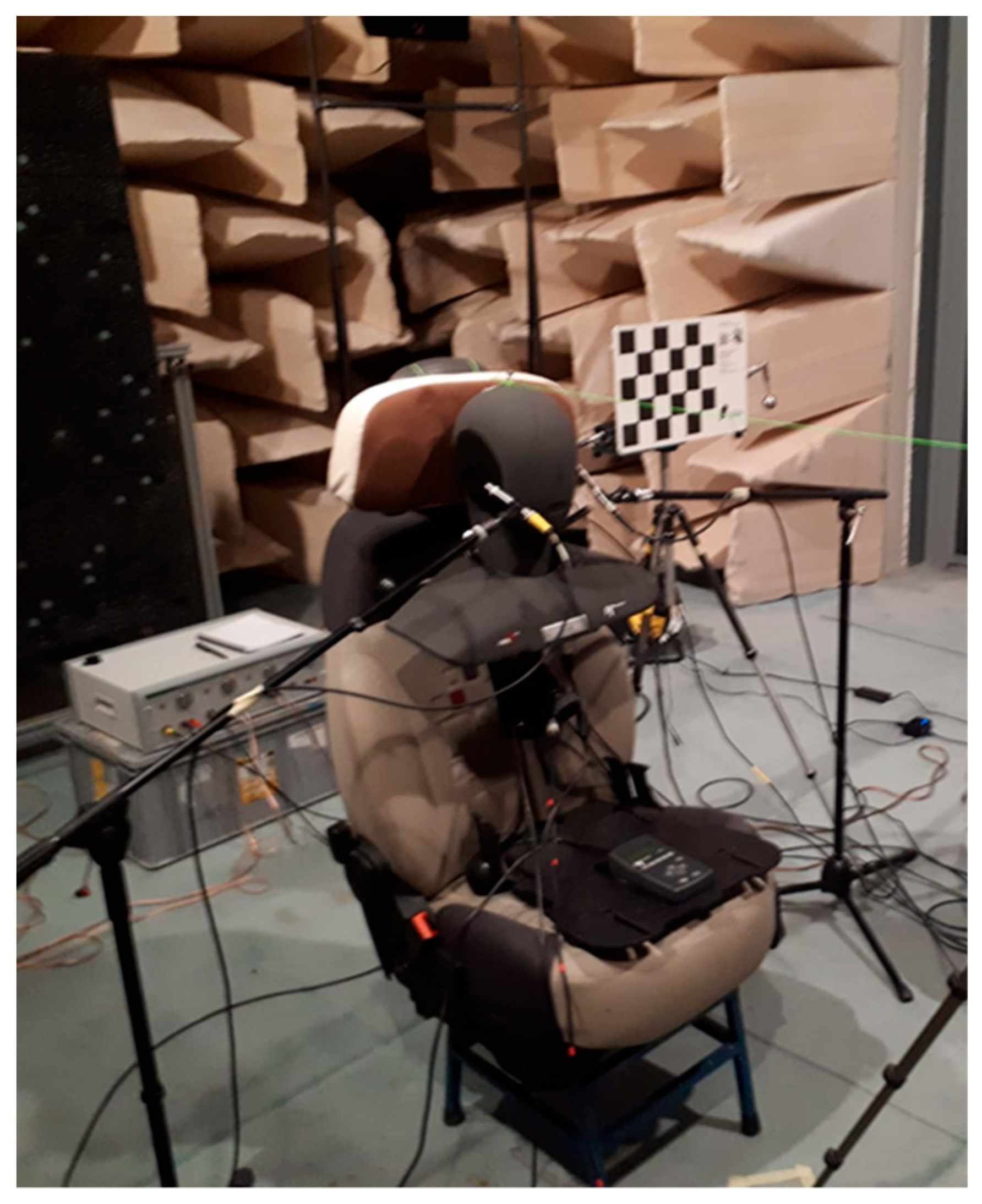
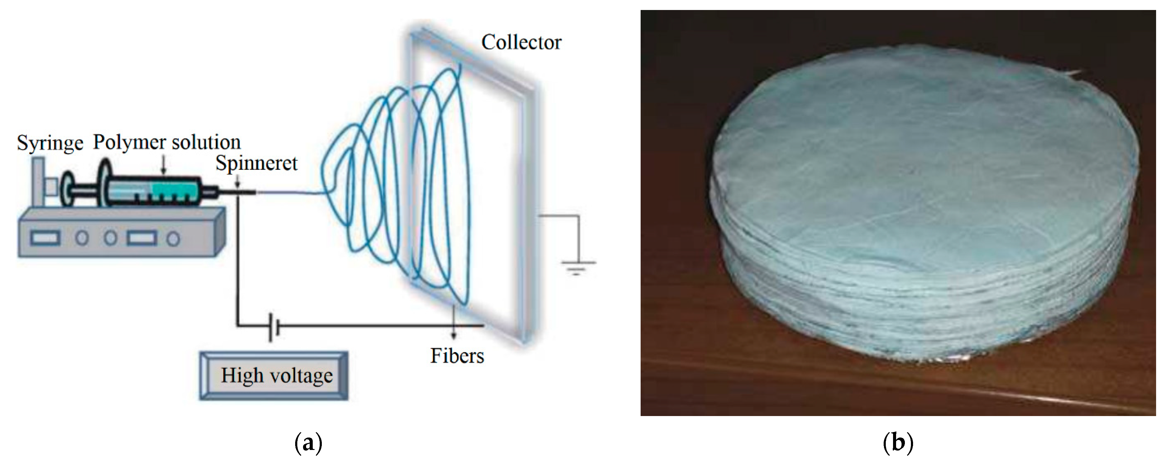
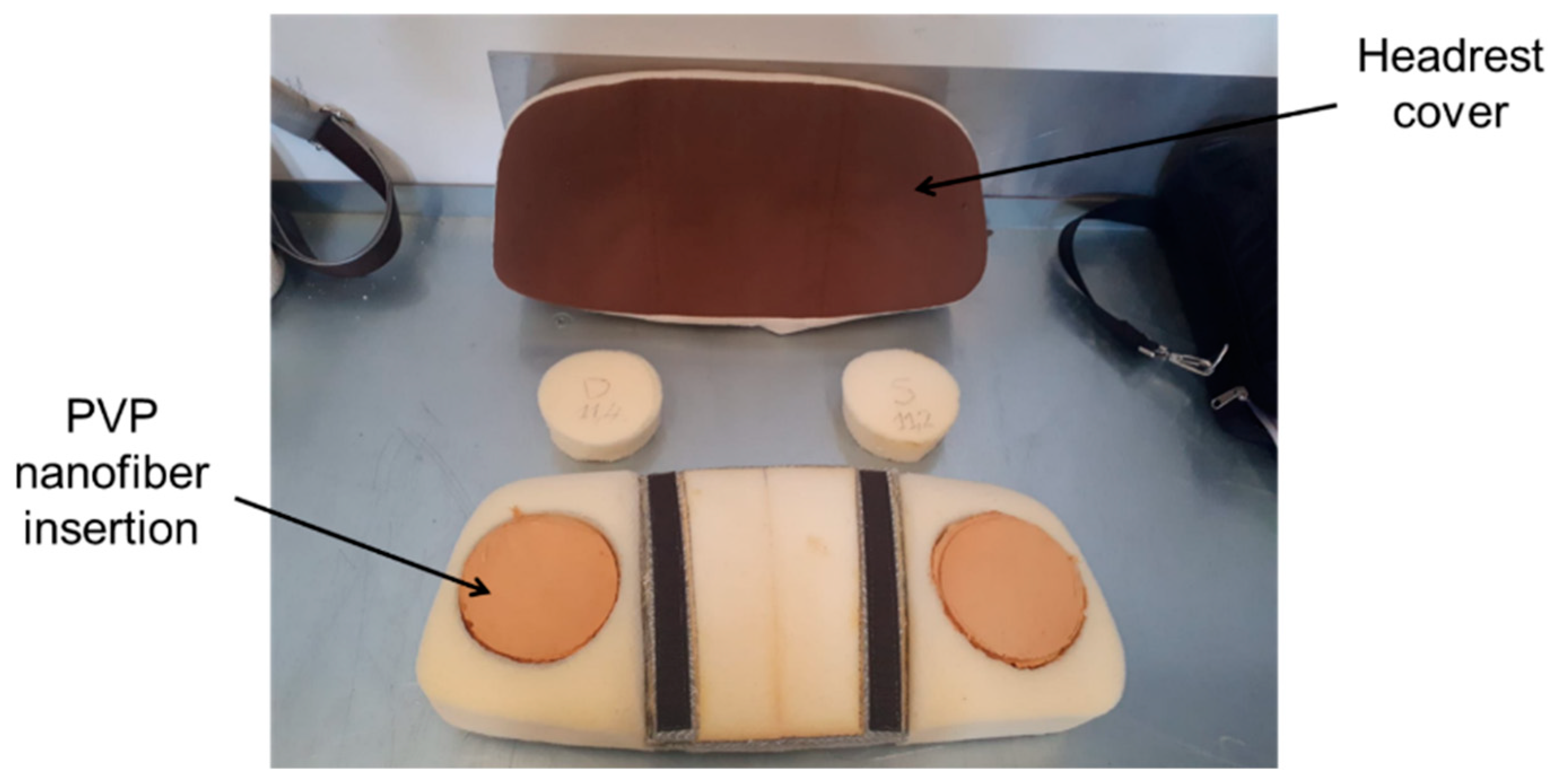
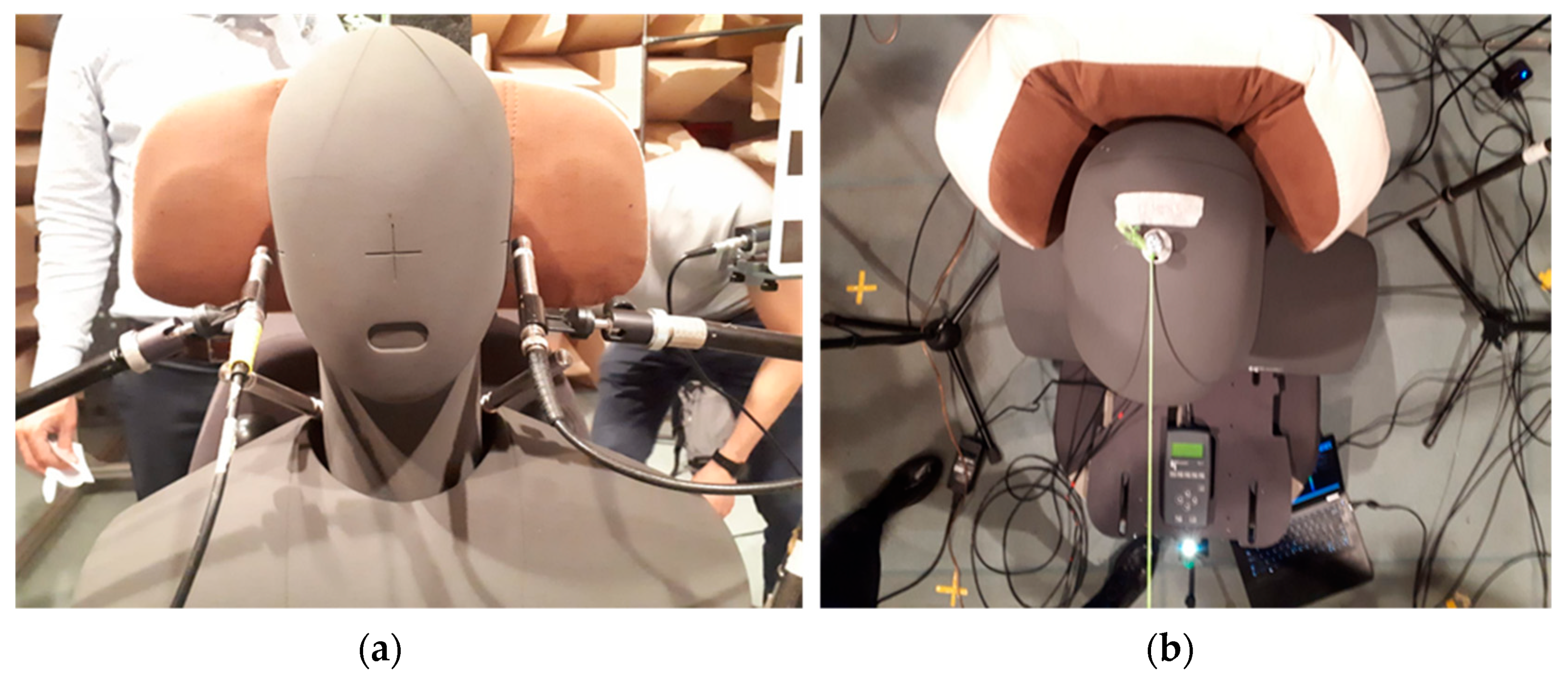
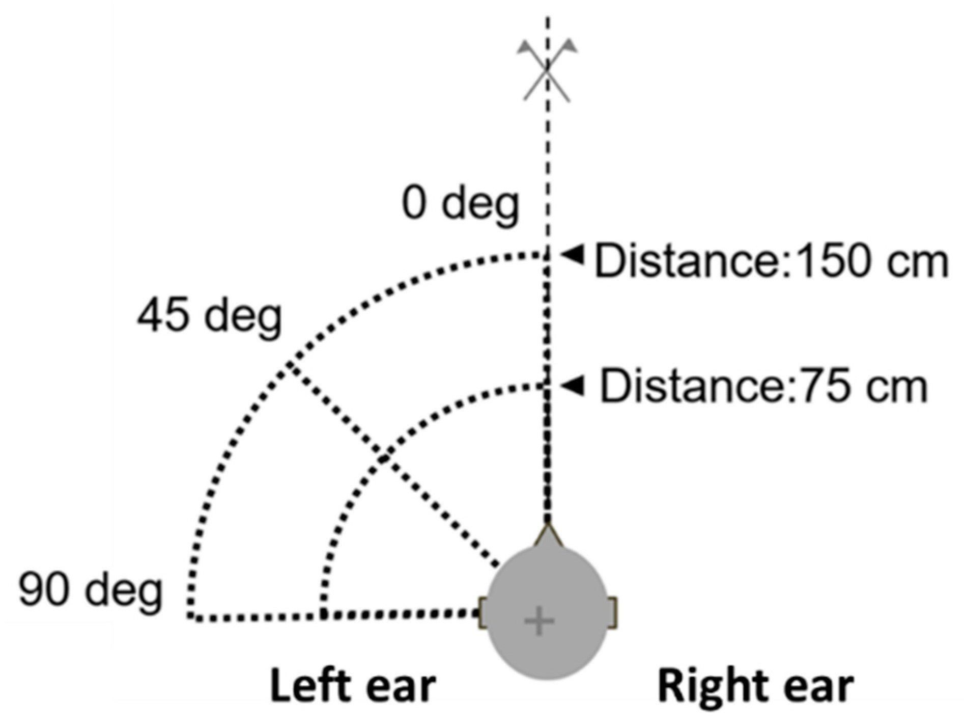
2. Experimental Campaign

The experimental campaign was conducted in a semi anechoic chamber at CIRA (Figure 1). A dummy headrest was characterized from an acoustical standpoint, in order to compare different configurations of headrest shape and fabrics. The main purpose was to understand which combination of shape and covering materials represented the best choice in terms of noise abatement for the aircraft seat’s headrest.
Additionally, the performances of an innovative nanofiber textile (Figure 2a) made of PVP plus silica inclusions [17,18,19,20,21,22] were assessed. Silica inclusions were added to the PVP nanomaterial to obtain the fire-resistant characteristics of the material and comply with flyability requirements. Such nanofiber textiles have appealing acoustic properties thanks to their small fiber dimensions that give a high surface-to-volume ratio. Such materials were made with an electro-spinning process (Figure 2b), which allowed us to obtain fibers with diameters of a few micrometers in the form of a textile with random fiber disposition. Several layers were then superimposed as in Figure 2b to obtain the desired mass or thickness.
In the current investigation, cylindrical insertions made with several layers of PVP nanofiber textiles were embedded in the caps of the dummy headrest, see Figure 3. Different configurations for the headrest were considered to evaluate the impact of the nanofiber insertions and of the headrest shape.
The insertions were added by cutting out two cylindrical sections from the headrest foam and replacing them with the nanofibrous material samples, preserving the overall mass of the headrest. Two geometries of the headrest were considered, referred to as “folded” and “unfolded” geometries hereinafter (Figure 4). In addition, the configurations including the original foam are referred to as the “baseline”, and those with nanofiber insertions as “insertion”.
The acoustic load consists of a monopole source positioned at different locations around the seat at head height. Figure 5 shows the different monopole source positions considered during the tests. Three different angles and two different distances from the binaural head were considered for each of the four headrest setups, thus, a total of 24 experiments were carried out. The final test matrix is reported in Table 1.
A calibrated volume velocity source (Simcenter Qsource), with emitted sound power spectrum, shown in Figure 6, was used as acoustic monopole source (Figure 7a). A periodic chirp was used as excitation signal and a binaural head (HEAD Acoustics HMS) was used to represent the passenger during the flight (Figure 7b). The frequency range of interest was set up to 1600 Hz with a resolution equal to 0.5 Hz. Four free-field microphones were positioned at ear height, whereas two microphones were already available inside the head’s ears (Figure 7b). Such a redundancy enables the assessment of the sound pressure levels over a larger area and with different microphone calibrations. The choice of the free-field microphones was motivated by the rather low-frequency range of the experiments. These were 1/2” 46AE GRAS microphones, with a nominal sensitivity of 50 mV/Pa.

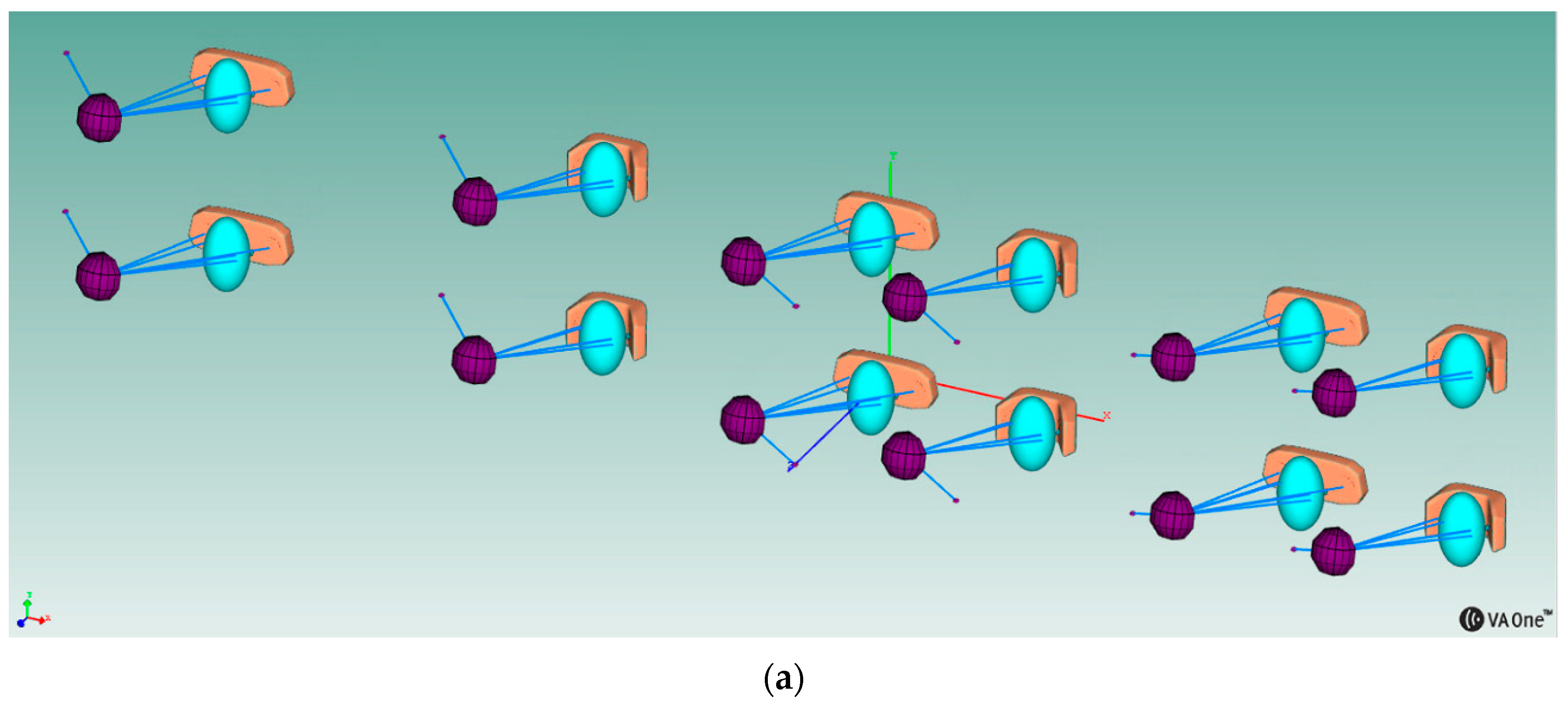
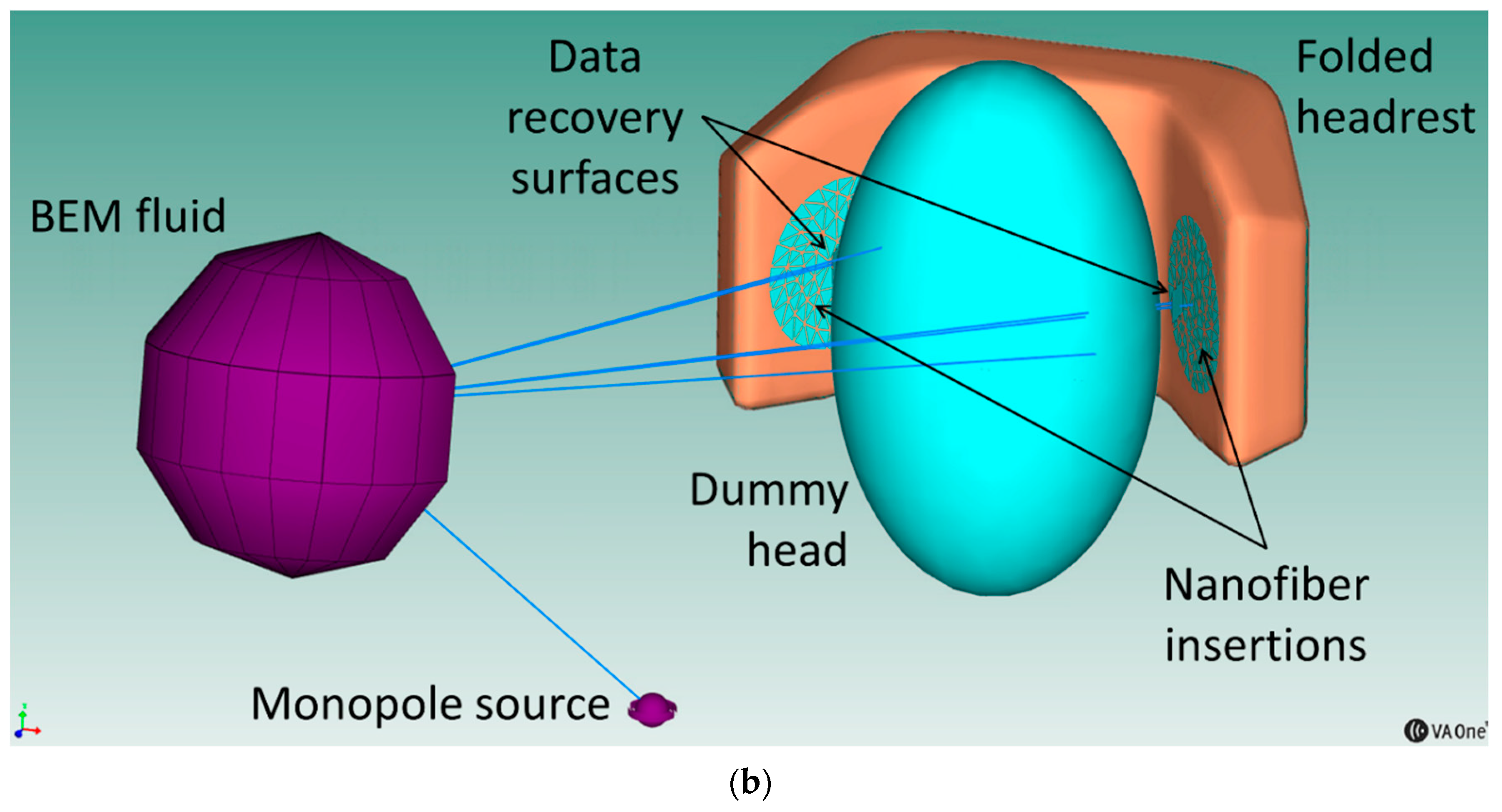
3. Numerical Simulations

Numerical simulations were performed with the aim to compare the related results with the experimental data measured in the semi-anechoic chamber. The commercial code VA One [26] was selected as numerical tool for such calculations. In particular, the BEM module was selected to simplify the modelling strategy thanks to the inherent advantages of BEM when simulating a free field radiation. The adoption of BEM (instead of FEM) allowed us to not model the surrounding walls (being perfectly absorbent in the considered frequency range), nor the fluid itself, eventually resulting in a closer similarity with the acoustic conditions reached in the semi-anechoic chamber.
A BEM formulation based on a Galerkin method [13,26] is used in this present work. This allows the generation of the modal radiation impedance matrix, the modal blocked force vectors due to internal acoustic sources and the nodes for computation of pressures and velocities due to internal acoustic sources and elastic modes of the BEM fluid subsystems. A direct BEM approach is adopted in this work because faces are wetted on one side only (BEM faces with single sides must fully enclose the fluid). The aforementioned BEM procedure is intended for mid-sized scattering, radiation and coupled problems, and the matrices used to describe the nodal impedance of a BEM fluid are complex and full. The memory and runtime needed to store and invert the matrices imposed constraints on the size of the model.
For an exterior problem as in the present case, the Burton–Miller formulation [27] is used to prevent spurious frequencies. An iterative flexible Generalized Minimal Residual method (fGMRES) [26] is used to compute the solution and a preconditioner to increase the convergence rate of the fGMRES iterative solver.
The headrest was modelled by CAD in the folded and unfolded configurations, see Figure 8. Particular attention was devoted to the separation of the two circular areas from the remaining part of the headrest in order to accommodate the two nanofiber insertions. Three different load locations, two headrest shapes and two types of circular insertions were considered for the simulations, for a total number of 12 different configurations (Figure 9a). Nominally, all of the configurations in Table 1, having the source position at 75 cm from the head, were reproduced numerically.
The final close up of one of the models is shown in Figure 9b, where the different entities are highlighted. The models are comprised of the BEM surface meshes for the headrest (with the circular insertions) and the dummy head, the monopole source representing the acoustic source, the BEM fluid definition and the two data recovery surfaces on which the acoustic measurements were displayed.
The considered frequency range was 200–1600 Hz, with 20 Hz constant resolution.
The mesh presented an average element size of nearly 15 mm that guaranteed about 15 nodes per wavelength at a frequency of 1600 Hz. It is a common practice to guarantee at least 4 to 8 nodes per wavelength to consider a mesh as sufficiently fine and, therefore, no convergence study was considered as required here. Simulations were performed up to 1600 Hz due to the availability of material data only up to that frequency (Figure 10). The monopole source was set up in such a way to emit the same power spectrum as in the experiments (Figure 6). The BEM fluid was air, with a sound speed equal to 343 m/s and mass density equal to 1.21 kg/m3. A null damping loss factor was assumed in air. The two circular insertions were modelled either having an area impedance corresponding to a traditional reference material or, alternatively, having the nanofiber textile impedance. PVP nanofiber textile and reference absorbing coefficients are shown in Figure 10. Such data were measured with a Kundt’s tube [17,18,19].

4. Results and Discussion

Charts of Sound Pressure Level as a function of frequency for the different configurations of headrest and source location are shown in Figure 11 for the experimental tests, and in Figure 12 for the numerical ones.
Based on the analysis of the results of Figure 11, the following comments can be highlighted:
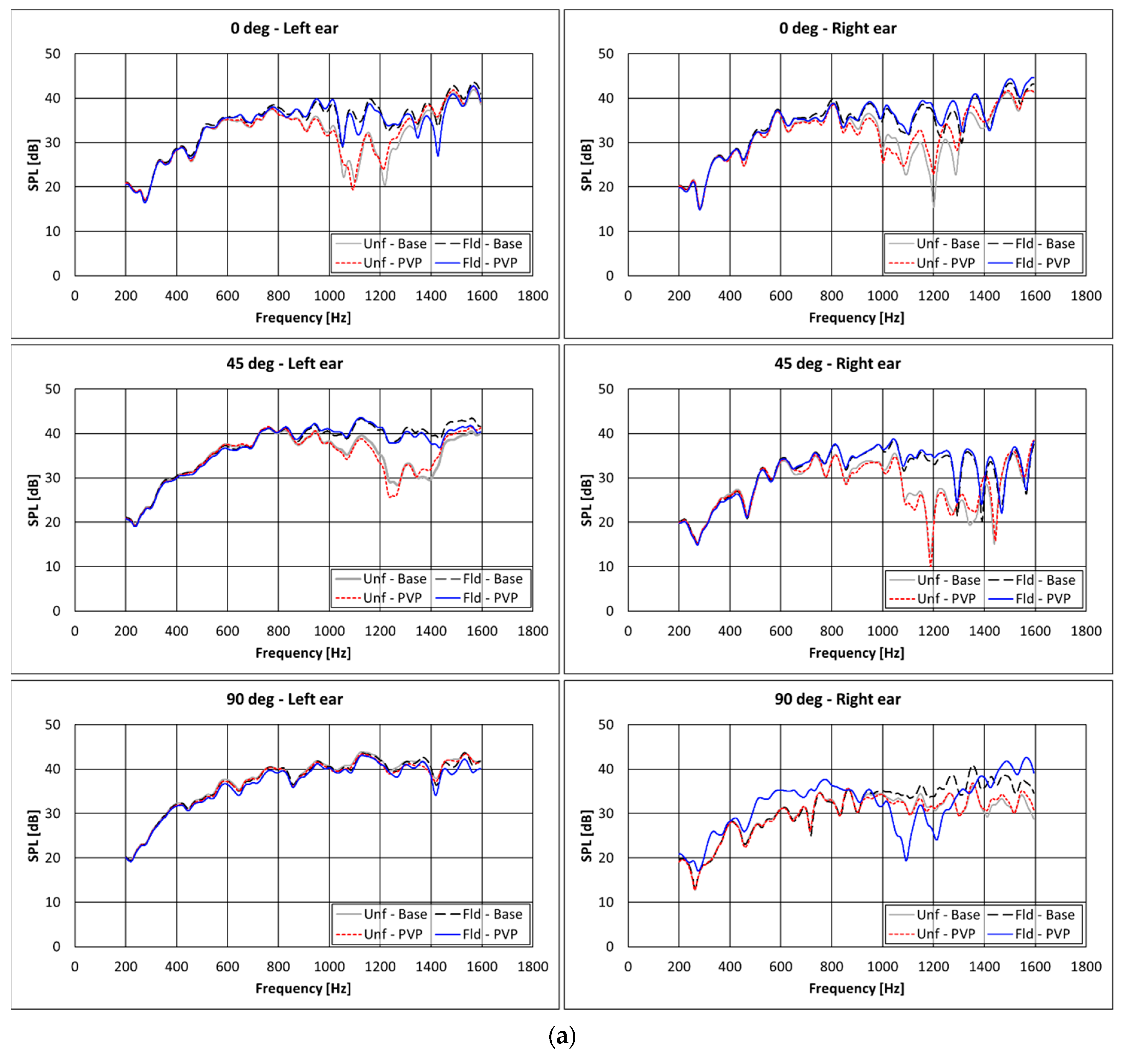
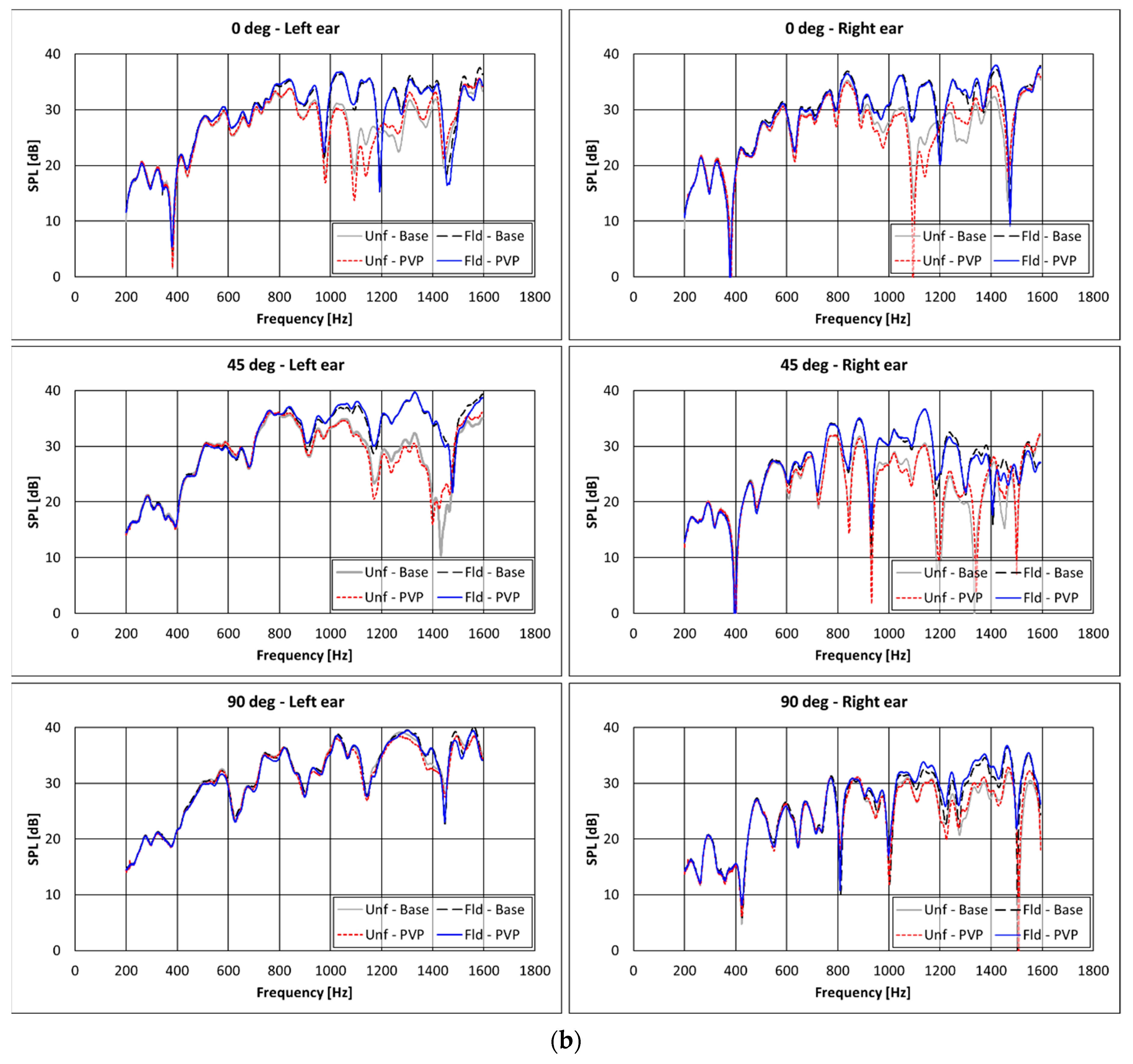
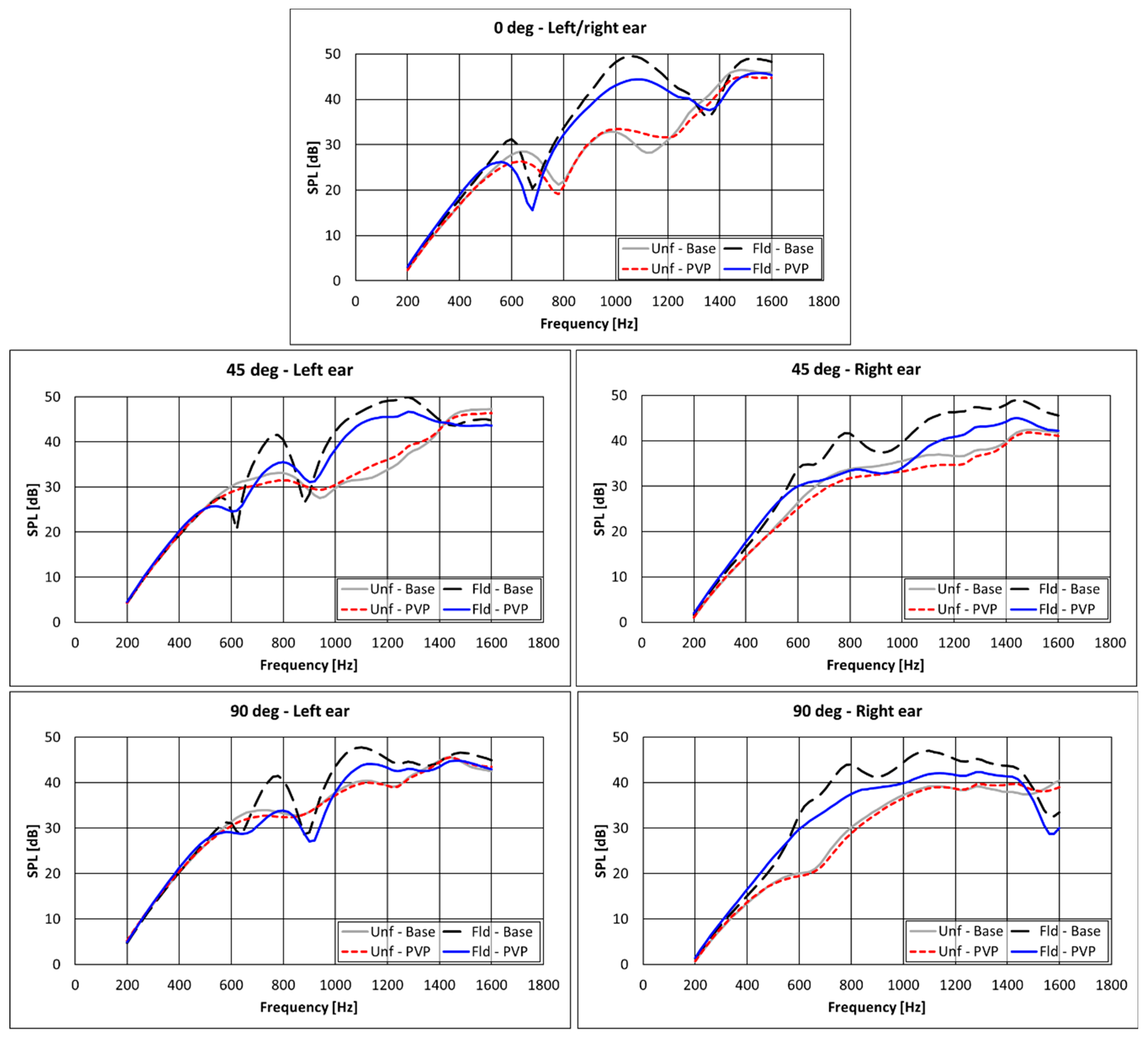
  • There are some improvements provided by the PVP nanofiber insertions for almost all the configurations in the range 800–1400 Hz, whereas no differences are observed when the monopole source is positioned at 90 deg.
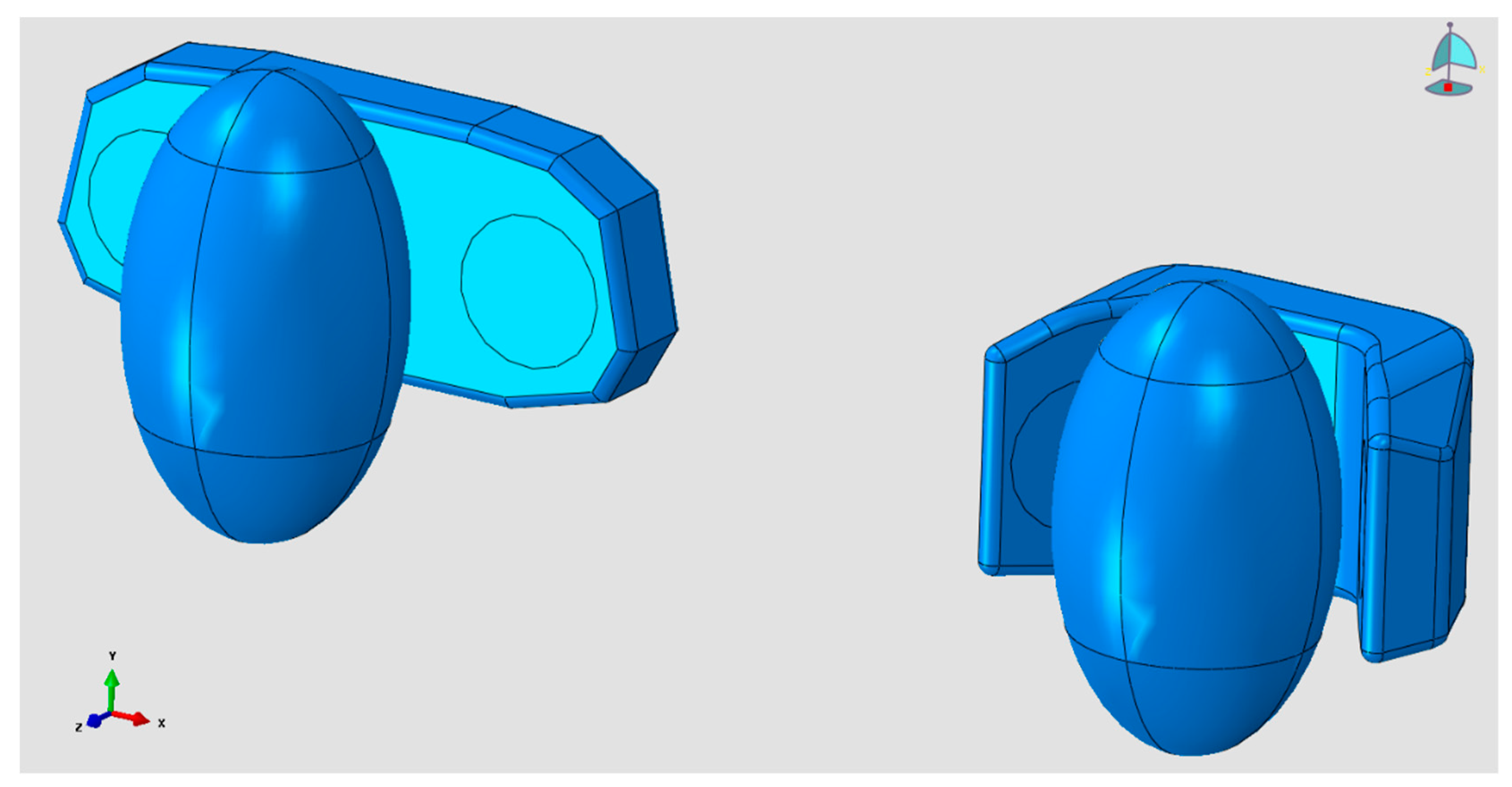
  • No significant effect of modifications of both headrest geometry and cover textile is noticeable below 600 Hz. This can be attributed to the fact that at such low frequencies the acoustic wavelengths are larger than the largest headrest size; therefore, no significant alterations in the sound field can be achieved by modifying the headrest shape.
  • Benefits of the different textiles and shapes on the SPL are lower when increasing the distance between the source and the headrest. Less benefits can be therefore expected when the acoustic sources are far from the headrest.
For a fair comparison of the presented numerical and experimental analyses, some elements of approximation should be taken into consideration. The nanofiber insertion impedances adopted in the simulation were measured for a textile thickness equal to nearly 1 cm, slightly different from the one adopted experimentally, close to 1.5 cm. Moreover, numerical simulations assumed the material’s impedance as independent from the angle of incidence and equal to the value obtained by experimental characterization with the Kundt’s tube [17,18,19]. Thereby, it was assumed a perfectly normal incidence of the sound waves, whereas in the studied scenario—as in most of the real-life conditions—acoustic excitations with a different angle of incidence are occurring. Despite these elements of approximations, the accordance between numerical and experimental trends was judged as acceptable.
All of the “unfolded” headrest configurations outperform the “folded” ones throughout the considered frequency range. Moreover, as also confirmed experimentally (Figure 11), significant attenuations were achieved in the range of 600–1400 Hz by the adoption of the PVP nanofiber insertions.
The highest acoustic load for an aircraft cabin during the cruise is the one generated by the external TBL, reaching a peak value at a frequency of nearly 1 kHz [23]. Hence, the adoption of these PVP insertions can also lead to some advantages in this critical low frequency range. Finally, further experimental and numerical investigations are also currently under development for frequencies higher than 1600 Hz.

5. Conclusions

This work presented the development of Passive Noise Control (PNC) concepts on aircraft headrests to enhance the acoustic comfort for passengers. Two PNC improvements of headrests were proposed to reduce the Sound Pressure Level (SPL) measured at the passengers’ ears in an aircraft cabin during flight; the first was based on the modification of the headrest shape, whereas the second was based on the adoption of an innovative nanofibrous textile as headrest covering material. These aspects were investigated through an experimental campaign conducted in a semi-anechoic chamber and through numerical simulations based on BEM for a correlation.
The two PNC concepts demonstrated having a non-negligible impact on the SPL measured at the passenger’s ears. Particularly, the adoption of the PVP nanofiber insertions and the unfolded shape have shown the best results in terms of noise abatement. More generally, it was found that the addition of lateral caps to the headrest negatively affected the SPL due to the sound wave reflected by them. Nonetheless, if caps were covered with high absorbent materials, these yielded a significant advantage, since larger high absorbent surfaces were available to dampen the sound. As a conclusion, due care should be paid to these PNC concepts since they can dampen more sound when used together instead of as standalone.

Author Contributions

Conceptualization, R.C. and M.B.; methodology, R.C. and M.B.; software, V.G.; validation, V.G., R.C. and M.B.; formal analysis, V.G.; investigation and experimental work, C.C., V.G. and J.C.; resources, C.C., J.C. and M.B.; writing—original draft preparation, V.G.; writing—review and editing, V.G., C.C., J.C. and R.C.; visualization, V.G.; supervision, R.C. and M.B. All authors have read and agreed to the published version of the manuscript.

Funding

The results have been mainly achieved in the framework of CASTLE—(Cabin Systems design toward passenger wellbeing) Core Partnership of Clean Sky 2 Program. CASTLE has received funding from the Clean Sky 2 Joint Undertaking under the European Union’s Horizon 2020 research and innovation program under grant agreement n° CS2-AIR-GAM-2014-2015-01. The contents of this paper reflect only the author’s views and the Clean Sky 2 Joint Undertaking and the European Commission are not liable for any use that may be made of the information contained therein.

Institutional Review Board Statement

Not applicable.

Informed Consent Statement

Not applicable.

Data Availability Statement

Data supporting the reported results can be obtained from the author upon request.

Acknowledgments

The authors would like to acknowledge F. Branda, University of Naples Federico II, for providing the PVP nanofiber textiles.

Conflicts of Interest

The authors declare no conflict of interest.

References

  1. Citarella, R.; Federico, L. Advances in Vibroacoustics and Aeroacustics of Aerospace and Automotive Systems. Appl. Sci. 2018, 8, 366. [Google Scholar] [CrossRef] [Green Version]
  2. Münzel, T.; Kröller-Schön, S.; Oelze, M.; Gori, T.; Schmidt, F.P.; Steven, S.; Hahad, O.; Röösli, M.; Wunderli, J.-M.; Daiber, A.; et al. Adverse Cardiovascular Effects of Traffic Noise with a Focus on Nighttime Noise and the New WHO Noise Guidelines. Annu. Rev. Public Heal. 2020, 41, 309–328. [Google Scholar] [CrossRef] [Green Version]
  3. Franssen, E.A.M.; Wiechen, C.M.A.G.V.; Nagelkerke, N.J.D.; Lebret, E. Aircraft noise around a large international airport and its impact on general health and medication use. Occup. Environ. Med. 2004, 61, 405–413. [Google Scholar] [CrossRef] [PubMed] [Green Version]
  4. Armentani, E.; Caputo, F.; Esposito, L.; Giannella, V.; Citarella, R. Multibody Simulation for the Vibration Analysis of a Turbocharged Diesel Engine. Appl. Sci. 2018, 8, 1192. [Google Scholar] [CrossRef] [Green Version]
  5. Armentani, E.; Giannella, V.; Parente, A.; Pirelli, M. Design for NVH: Topology optimization of an engine bracket support. Procedia Struct. Integr. 2020, 26, 211–218. [Google Scholar] [CrossRef]
  6. Citarella, R.; Landi, M. Acoustic analysis of an exhaust manifold by Indirect Boundary Element Method. Open Mech. Eng. J. 2011, 5, 138–151. [Google Scholar] [CrossRef] [Green Version]
  7. Armentani, E.; Trapani, R.; Citarella, R.; Parente, A.; Pirelli, M. FEM-BEM Numerical Procedure for Insertion Loss Assessment of an Engine Beauty Cover. Open Mech. Eng. J. 2013, 7, 27–34. [Google Scholar] [CrossRef]
  8. Barbarino, M.; Adamo, F.P.; Bianco, D.; Bartoccini, D. Hybrid BEM/empirical approach for scattering of correlated sources in rocket noise prediction. J. Sound Vib. 2017, 403, 90–103. [Google Scholar] [CrossRef]
  9. Armentani, E.; Giannella, V.; Citarella, R.; Parente, A.; Pirelli, M. Substructuring of a Petrol Engine: Dynamic Characterization and Experimental Validation. Appl. Sci. 2019, 9, 4969. [Google Scholar] [CrossRef] [Green Version]
  10. Barbarino, M.; Bianco, D. A BEM–FMM approach applied to the combined convected Helmholtz integral formulation for the solution of aeroacoustic problems. Comput. Methods Appl. Mech. Eng. 2018, 342, 585–603. [Google Scholar] [CrossRef]
  11. Bianco, D.; Adamo, F.P.; Barbarino, M.; Vitiello, P.; Bartoccini, D.; Federico, L.; Citarella, R. Integrated Aero–Vibroacoustics: The Design Verification Process of Vega-C Launcher. Appl. Sci. 2018, 8, 88. [Google Scholar] [CrossRef] [Green Version]
  12. Giannella, V.; Lombardi, R.; Pisani, M.M.; Federico, L.; Barbarino, M.; Citarella, R. A Novel Optimization Framework to Replicate the Vibro-Acoustics Response of an Aircraft Fuselage. Appl. Sci. 2020, 10, 2473. [Google Scholar] [CrossRef] [Green Version]
  13. Kirkup, S. The Boundary Element Method in Acoustics: A Survey. Appl. Sci. 2019, 9, 1642. [Google Scholar] [CrossRef] [Green Version]
  14. Yin, J.; Rossignol, K.-S.; Barbarino, M.; Bianco, D.; Testa, C.; Brouwer, H.; Janssen, S.R.; Reboul, G.; Vigevano, L.; Bernardini, G.; et al. GARTEUR activities on acoustical methods and experiments for studying on acoustic scattering. CEAS Aeronaut. J. 2018, 10, 531–551. [Google Scholar] [CrossRef]
  15. Brancati, A.; Aliabadi, M.H.; Mallardo, V. A BEM sensitivity formulation for three-dimensional active noise control. Int. J. Numer. Methods Eng. 2012, 90, 1183–1206. [Google Scholar] [CrossRef]
  16. Brancati, A.; Aliabadi, M. Boundary element simulations for local active noise control using an extended volume. Eng. Anal. Bound. Elements 2012, 36, 190–202. [Google Scholar] [CrossRef]
  17. Rajappan, S.; Bhaskaran, P.; Ravindran, P. An Insight into the Composite Materials for Passive Sound Absorption. J. Appl. Sci. 2017, 17, 339–356. [Google Scholar] [CrossRef]
  18. Khan, W.S.; Asmatulu, R.; Yildirim, M.B. Acoustical Properties of Electrospun Fibers for Aircraft Interior Noise Reduction. J. Aerosp. Eng. 2012, 25, 376–382. [Google Scholar] [CrossRef]
  19. Avossa, J.; Branda, F.; Marulo, F.; Petrone, G.; Guido, S.; Tomaiuolo, G.; Costantini, A. Light Electrospun Polyvinylpyrrolidone Blanket for Low Frequencies Sound Absorption. Chin. J. Polym. Sci. 2018, 36, 1368–1374. [Google Scholar] [CrossRef] [Green Version]
  20. Branda, F.; Marulo, F.; Guido, S.; Petrone, G.; Del Sorbo, G.R.; Truda, G.; Tomaiuolo, G. Polyvinylpyrrolidone (PVP)/Graphene based soundproofing materials through electrospinning. In Proceedings of the INTER-NOISE 2017—46th International Congress and Exposition on Noise Control Engineering: Taming Noise and Moving Quiet, Hong Kong Convention and Exhibition Centre (HKCEC), Hong Kong, China, 27–30 August 2017. [Google Scholar]
  21. Del Sorbo, G.R.; Truda, G.; Bifulco, A.; Passaro, J.; Petrone, G.; Vitolo, B.; Ausanio, G.; Vergara, A.; Marulo, F.; Branda, F. Non Monotonous Effects of Noncovalently Functionalized Graphene Addition on the Structure and Sound Absorption Properties of Polyvinylpyrrolidone (1300 kDa) Electrospun Mats. Materials 2019, 12, 108. [Google Scholar] [CrossRef] [Green Version]
  22. Giannella, V.; Branda, F.; Passaro, J.; Petrone, G.; Barbarino, M.; Citarella, R. Acoustic Improvements of Aircraft Headrests Based on Electrospun Mats Evaluated Through Boundary Element Method. Appl. Sci. 2020, 10, 5712. [Google Scholar] [CrossRef]
  23. Petrone, G.; Melillo, G.; Laudiero, A.; De Rosa, S. A Statistical Energy Analysis (SEA) model of a fuselage section for the prediction of the internal Sound Pressure Level (SPL) at cruise flight conditions. Aerosp. Sci. Technol. 2019, 88, 340–349. [Google Scholar] [CrossRef]
  24. Giannella, V.; Citarella, R.; Barbarino, M.; Vitiello, P.; Bianco, D.; Petrone, G. Passive Noise Control oriented design of aircraft headrests. In Proceedings of the INTER-NOISE 2019 MADRID—48th International Congress and Exhibition on Noise Control Engineering, Madrid, Spain, 16–19 June 2019. [Google Scholar]
  25. Mallardo, V.; Aliabadi, M.; Brancati, A.; Marant, V. An accelerated BEM for simulation of noise control in the aircraft cabin. Aerosp. Sci. Technol. 2012, 23, 418–428. [Google Scholar] [CrossRef]
  26. ESIGroup. VA One Users’ Guide; ESIGroup: Paris, France, 2019. [Google Scholar]
  27. Burton, A.J.; Miller, G.F. The application of integral equation methods to the numerical solution of some exterior boundary-value problems. In Proceedings of the Royal Society of London. A. Mathematical and Physical Sciences; The Royal Society: London, UK, 1971; Volume 323, pp. 201–210. [Google Scholar]
Figure 1. Semi-anechoic chamber at CIRA: the setup consists of a dummy seat with binaural head and configurable headrest.
Applsci 11 06400 g001
Figure 2. (a) Schematic view of the electrospinning process; (b) layers of nanofiber textile [19].
Applsci 11 06400 g002
Figure 3. Configurable headrest adopted for the experimental investigations.
Applsci 11 06400 g003
Figure 4. Different headrest geometries considered for the experimental investigations: (a) unfolded and (b) folded.
Applsci 11 06400 g004
Figure 5. Monopole source positioning for the experimental measurements.
Applsci 11 06400 g005
Figure 6. Sound Power Level [dB] emitted by the LMS “Q source”.
Applsci 11 06400 g006
Figure 7. (a) Calibrated monopolar volume velocity source (Simcenter Qsource) and (b) binaural head (HEAD Acoustics HMS) adopted for the tests.
Applsci 11 06400 g007
Figure 8. CAD models for the head and the folded and unfolded configurations.
Applsci 11 06400 g008
Figure 9. (a) BEM models; (b) close up of the model for the folded headrest and the monopole source positioned at 0°.
Applsci 11 06400 g009aApplsci 11 06400 g009b
Figure 10. Absorbing coefficients for PVP nanofiber textile and the reference material.
Applsci 11 06400 g010
Figure 11. Experimental results in terms of SPL vs. frequency spectra for different headrest’s configurations; monopole source at a distance equal to (a) 75 cm or (b) 150 cm; “PVP” or “Base” refer to the configurations with or without the PVP + silica nanofibrous insertions in the caps.
Applsci 11 06400 g011aApplsci 11 06400 g011b
Figure 12. Numerical results in terms of SPL spectra for different headrest’s configurations. Monopole source at a distance equal to 75 cm. “PVP” or “Base” refer to the configurations with or without the PVP + silica nanofibrous insertions in the caps.
Applsci 11 06400 g012
Table 1. Experimental test matrix.
Headrest ConfigurationShapeDistance [m]Angle [°]
BaselineFolded0.75 m0
BaselineFolded0.75 m45
BaselineFolded0.75 m90
BaselineFolded1.5 m0
BaselineFolded1.5 m45
BaselineFolded1.5 m90
BaselineUnfolded0.75 m0
BaselineUnfolded0.75 m45
BaselineUnfolded0.75 m90
BaselineUnfolded1.5 m0
BaselineUnfolded1.5 m45
BaselineUnfolded1.5 m90
InsertionFolded0.75 m0
InsertionFolded0.75 m45
InsertionFolded0.75 m90
InsertionFolded1.5 m0
InsertionFolded1.5 m45
InsertionFolded1.5 m90
InsertionUnfolded0.75 m0
InsertionUnfolded0.75 m45
InsertionUnfolded0.75 m90
InsertionUnfolded1.5 m0
InsertionUnfolded1.5 m45
InsertionUnfolded1.5 m90
BaselineFolded0.75 m0
BaselineFolded0.75 m45
BaselineFolded0.75 m90
BaselineFolded1.5 m0
BaselineFolded1.5 m45
BaselineFolded1.5 m90
BaselineUnfolded0.75 m0
BaselineUnfolded0.75 m45
BaselineUnfolded0.75 m90
BaselineUnfolded1.5 m0
BaselineUnfolded1.5 m45
BaselineUnfolded1.5 m90
Publisher’s Note: MDPI stays neutral with regard to jurisdictional claims in published maps and institutional affiliations.

