
Monitoring the Impact of the Large Building Investments on the Neighborhood


Department of Geotechnics and Roads, Silesian University of Technology, 44-100 Gliwice, Poland
Appl. Sci. 2021, 11(14), 6537; https://doi.org/10.3390/app11146537
Submission received: 10 June 2021
/
Revised: 9 July 2021
/
Accepted: 14 July 2021
/
Published: 16 July 2021
(This article belongs to the Special Issue New Frontiers in Sustainable Geotechnics)
Abstract
:The article presents the concept of monitoring buildings and infrastructure elements located near large construction investments (the construction of high-rise buildings of the Oak Terraces housing estate in Katowice and the construction of a tunnel under the roundabout in Katowice along the intercity express road DTŚ). The impacts include deep excavation, lowering of the groundwater level over a large area, and dynamic influences related to the use of impact methods of soil improvement. The presented monitoring includes observation of the groundwater level with the use of piezometers, geodetic measurements of settlement and inclinations, as well as the measurement of vibration amplitudes generated during the works involving shocks and vibrations. It was also important to observe the development of cracks on the basis of a previously made inventory of damage. The results of the monitoring allow corrections to be made in the technology of works (e.g., reduction of vibration amplitudes, application of additional protections at excavations, etc.) or the use additional safety measures. Currently, there are also monitoring systems used during the operation of completed facilities.
1. Introduction
Monitoring of the impact of works on the environment is one of the most important elements enabling the safe implementation of investment projects in urban development [1,2]. Due to the fact that works are carried out near existing buildings, including high-rise buildings, various types of observations and measurements must be carried out, on the basis of corrections in the field of works technology (e.g., reducing the amplitudes of vibrations, using a different type of driving element in the ground, changing the frequency of soil compaction, etc.) as well as suitable safety measures that can be introduced [3]. Currently, due to the increasingly scarce availability of land for development, investors are often forced to carry out construction works near other facilities [4] (with a risk of damaging adjacent buildings) and on poor grounds [5] (e.g., anthropogenic embankments with a high variability of granulometric composition and state of compaction, organic soils, etc.). Effective methods of ground improvement as well as technologies which allow the introduction of structural elements constituting an intermediate foundation or protection of scarps or excavation walls use shocks or vibrations [6]. They are usually destructive to nearby structures and can cause various types of damage, breakdowns, or even construction disasters. In addition, due to the need to optimize spatial development, it is often necessary to make deep excavations, which may also pose a threat to existing buildings [7,8,9,10].
Properly implemented monitoring should comprise a comprehensive program of continuous observation, which would enable a fast reaction in the event of a threat [11,12]. Such a program must be properly planned at the design stage and properly implemented during construction works. Sometimes, measurements and observations during the operation stage are also provided for, as harmful influences may also occur during this period [13,14].
One of the most destructive impacts of dense urban development involves deep excavation works. Very often, the level of the trench bottom is lower than the foundation level of the neighboring objects, and the works are carried out in close contact with another building. Often, the neighboring structures are in bad technical condition, or their structures are very sensitive to additional horizontal displacements and settlements resulting from the works being carried out, and hence very strict restrictions in this respect are imposed [15,16]. A separate problem is to ensure the stability of high scarps or walls of the excavations under high ground load. Another type of harmful effect involves a temporary lowering of the groundwater level during the excavation works [17]. Such a lowering may be from a few to a dozen or so meters and can cause additional settlements of up to several cm [18]. Especially in the case of complex ground conditions, uneven settlement may be the cause of various types of structural damage. Despite the increase in the value of mean stresses in the subsoil, which generally increases the subsoil bearing capacity, accompanying settlements under existing buildings is almost always a danger.
Particularly, destructive effects occurring during the execution of construction works are shocks and the result of vibrations propagating in the soil medium [19]. Since typical building structures, located in non-seismic areas, are not resistant to such influences, we can frequently observe damage or failures effected by dynamic influences. Some of the applied ground strengthening technologies, such as, for example, dynamic consolidation, making stone columns, or driving prefabricated piers or elements of sheet piling, may cause similar damage, as in the case of seismic or paraseismic tremors (e.g., mining tremors). Harmful vibrations can also occur during the transport of materials or other types of movement of heavy vehicles or construction machinery.
In the south of Poland, where the monitored investments described in the article were implemented, mining deformations are a significant problem accompanying construction sites. They are manifested by a lowering of the surface area, and additionally, inclinations, curvature of the surface area, and horizontal deformations. Mining deformations also adversely affect buildings and infrastructure elements within the impact range, sometimes causing damage. Sometimes, different kinds of influences overlap with the final deformation of the surface area, which translates into settlement and horizontal displacement of buildings. Hence, there is a need to take into account all factors that may affect the course of the monitored process [20,21,22]. Only in this case can the results of monitoring be reliable and contribute to the protection of endangered objects.
Due to the nature of the impacts caused by construction works on neighboring facilities, the standards in force in Poland impose very strict requirements in terms of permissible values (displacements and vibration amplitudes), which often prevents the use of some very effective technologies, and sometimes also puts into question the realization of some investments in dense building developments. On the other hand, predictions often differ from later observations. Additionally, the technical condition of the structures subjected to hazard or ground conditions in the place where the works are carried out has a great influence. Hence, monitoring of the impact is very often a prerequisite for safe implementation of an investment project. The aim of the article is to present the experience gained during the implementation of the monitoring ring, using the examples of two large investments in Silesia. Possible measurement techniques were tried, which can be applied in practice for many larger building investments.
2. Materials and Methods
The following part of the article presents the monitoring of two large investments carried out in Katowice in the south of Poland (Figure 1). The first one is the construction of a tunnel under the roundabout along an intercity route through the city center. The second one is the construction of a large housing estate. Both projects were carried out in the vicinity of other buildings, hence many facilities were within the range of impact of the realized construction works.
The first element involving the monitoring of the impact of works on the structural condition of objects is the inventory of the state of objects at risk of the impact. The scope of observation and, above all, the requirements involving permissible impacts, should depend on the type of structure and its technical condition. For new structures in good condition, slightly higher impacts may be allowed. Yet, when the inventory reveals the presence of excessive damage, it may necessitate a change in the execution technology of works, or the use of additional reinforcements or protections. When assessing the technical condition of objects before starting monitoring, special attention should be paid to visible cracks, in particular on reinforced concrete and masonry structures (Figure 2b). Cracks on finishing elements (plaster, glaze, etc.) do not constitute any threat to the safety of use of the object, yet they indicate the occurrence of accelerated wear of the object and are the first sign of the object’s lower resistance to future impacts.
The monitoring should be carried out on the basis of an appropriate design project. Detailed arrangements regarding the types and frequency of observations, as well as the procedures to be followed in the event of excessive impacts, should take into account the technology used for the execution of works, the relevant safeguards, and the conclusions from the inventory of technical conditions. An appropriate monitoring program should optimize the number of tests and observations to be carried out, the frequency, and costs. It must not be forgotten that some tests may be burdensome for the contractor. Nowadays, increasingly complex automatic measurement systems are used, which enable quick detection of the risk of unfavorable impacts on objects [23,24].
A particularly important aspect of the presented monitoring involves the observation of the development of cracks noticed during the inventory. A plexiglass plate is glued to existing cracks (Figure 2b), which enables the observation of the development of cracks during the execution of works, in particular the growth of their openings. Modern monitoring and diagnostic programs of structures use crackmeters for measurements [25]. Additionally, the observation should take into account the development of a new cracks or other damage. The above observations are the most significant data to be applied for expert assessments involving the harmfulness of the impacts on a given object.
The first of the presented types of research is observation of the groundwater level, which is lowered at the stage of excavation and construction of underground elements. To determine the extent of lowering, piezometers made beforehand in the subsoil are used. They consist of a perforated pipe covered with sand. Inside it, the groundwater stabilizes on an ordinate consistent with its piezometric level in the surrounding ground. The measurement of this level is carried out by a device inserted inside the pipe into the water collected inside it. The measurement can be carried out in a traditional way with the use of devices emitting an acoustic signal when contacted with the water surface, or in an electronic way. In modern systems, we can also measure water temperature, direction, and speed of filtration, and we can monitor the quality of water and its degree of contamination [26].
It is particularly important in the applied monitoring to perform geodetic measurements of settlement and displacements in the horizontal plane. Measurements of this type have been used for a long time, and they have been now innovated by the introduction of automation in measurements, which allows for faster responses when the permissible values are exceeded [27,28]. Reports on geodetic measurements enable to analyze the impact of works on neighboring buildings at any time. The implementation of geodetic measurements requires prior installation of benchmarks (for the measurements of settlements) and measurement points (for monitoring displacements), which make up the measurement matrix (Figure 2a). The design of such a control system should be based on the assessment of the range of anticipated impacts and the inventory of damage identified before the commencement of works.
Finally, the last of the discussed methods involves measurements of vibrations generated on the structures of objects which are within the range of impact. Most often, accelerometers (Figure 3a) are used to measure accelerations in the structural elements of objects [29,30]. Less frequently, the amplitudes of displacements or velocities are measured. To be able to realistically assess the destructive impact, in addition to the amplitude values, it is also important to know the corresponding frequencies. The frequency range most dangerous for building structures is 5–25 Hz (Figure 3b). In some countries, appropriate monograms have been developed to assess the vibration risk level for certain types of buildings. In general, the permissible values should be determined on the basis of structure type and the technical conditions of a given building. Vibration monitoring is particularly helpful in verifying the safety measures used during the works.
While discussing various types of measurements carried out in-situ with sensors installed on the structures of monitored buildings, the accuracy of the measurements must not be overlooked. The accuracy of geodetic measurements (both settlements and deflections of objects) can reach ± 1 mm. Currently used measuring instruments can offer greater precision of measurement, however, for the purposes of monitoring, such accuracy is sufficient. In the case of groundwater level measurements in piezometers, an accuracy of ± 0.1 m is completely sufficient. It allows for a sufficiently precise assessment of the influence on the behavior of nearby objects. On the other hand, vibration measurements should already be carried out with greater accuracy. It is easiest to carry out the acceleration measurements, where most of the commonly used equipment ensures a measurement accuracy of ±1 mm/s2. Such accuracy allows the use of various types of scales (Figure 3b) developed to assess the impact of dynamic influences. In Polish standards, the basic quantity at which the impact of vibrations on structures is assessed is the acceleration amplitude, although in many other countries such a quantity is the velocity amplitude. Measurements of velocity and displacements of vibration would require using equipment that guarantees a much greater precision of measurements, hence such measurements are less often used in practice.
It is of great importance when designing a monitoring system to be able to define the frequency of the measurements carried out. During the realization of earthworks and geoengineering works, the intervals between measurements should be short enough to react duly to a possible threat to the safety of neighboring buildings. These intervals can be slightly extended right after the completion of the works (their effects may remain in the structures for some time). Frequently, monitoring is also carried out during the operation of the finished object, when the frequency of measurements is even lower. Sometimes the dates of tests are selected based on weather conditions (season of year). In the past, due to costs, it was necessary to limit the number of measurements and the time of monitoring. Currently, with the introduced automation of measurement, registration processes, archiving, and even automatic responses, the costs of monitoring are much lower, hence the growing popularity of its use. The monitoring system fits perfectly into the BIM system, which is becoming standard in the implementation of larger investments [31].
3. Results
3.1. Construction of a Tunnel under the Roundabout in Katowice
The following section presents examples of the monitoring carried out at two construction sites in Silesia. The first one involves the construction of a tunnel along the intercity express road (DTŚ) under the roundabout in Katowice, where underground works were carried out in 2005. The preparatory works, including the lowering of the groundwater level, started in mid-2004. As part of the investment project, a tunnel 650 m long and 30.4 m wide was constructed under an important road intersection in the center of the capital of Upper Silesia (Figure 4). The excavations for the tunnel were carried out using the ceiling method. The structure of the tunnel consists of two floor slabs (lower and upper) with a thickness of 1.05–1.27 m supported on diaphragm walls 0.8 m thick (Figure 5). The said walls make up both the tunnel casings and limit the extent of the depression crater resulting from the temporary (for the duration of the works) lowering of the groundwater level by approximately 5 m. Additionally, a diaphragm wall was built in the middle between two parts of the tunnel, which contained traffic lanes in both directions. The length of the diaphragm wall was 17 m from the ground level, while the length of the piezometers used was 25 m. Since the ceiling of impermeable grounds (rock grounds-claystone and siltstone) was too deep, it was not possible to bring down the diaphragm walls to the impermeable grounds. Subsoil above the rocky soils was composed of medium and fine sands in a medium dense or dense state (see Figure 6). Consequently, the diaphragm walls only partially limited the range of the depression crater. Hence, the need to observe the groundwater level in the area adjacent to the construction site.
The frequency of measurements as part of the monitoring carried out is presented in Table 1.
The objects subjected to the hazard are located along the tunnel under construction (Figure 3). It was assumed that the range of the harmful influence was approximately 200 m on each side of the construction site. This resulted from the depression crater estimated in the technical project. The buildings subjected to hazard (Figure 7, Figure 8, Figure 9 and Figure 10) include the sports and entertainment hall “Spodek” (Saucer), high-rise residential or office buildings (over 20 above-ground stories), and many other structures. Some of them were in poor technical condition. The results of selected measurements carried out as part of the monitoring are shown in Figure 11, Figure 12, Figure 13, Figure 14 and Figure 15. In addition, in many cases, an increase in crack width was found (up 2 mm, mean 0.2–0.3 mm), which speaks to the real impact of the performed works on the condition of the structures. Cracks were most common on walls on the basement or ground floors (see Figure 2b) and were located near windows or ceilings.
3.2. Construction of the Housing Estate “Oak Terraces” in Katowice
The second of the analyzed investment projects involved the construction of the housing estate “Oak Terraces” in Katowice (Figure 16). As part of the investment project realized since 2006 and divided into four stages, a total of 4 large buildings with 12 above-ground stories and 8 small 4-storey buildings are constructed (Figure 17). All buildings had one underground story. A subsoil up to a depth of up to 20 m below the ground level was formed by anthropogenic embankments composed of coal waste. The embankments were characterized by a very variable granulometric composition and state of compaction. Below there were very load-bearing and stiff rocky ground. The works that had a destructive impact on the neighborhood involved strengthening of the subsoil by means of the dynamic consolidation method [32]. In the applied technology, a heavy rammer is used for soil compaction whereby shocks are produced causing vibrations harmful to nearby objects [33]. The situation was complicated by the poor technical condition of the buildings within the impact range. The said objects were most often single-family houses with masonry structures, with Klein or wooden ceilings, without additional stiffening in the form of wreaths. Many cracks were found on the buildings, and the condition of the structures themselves was a cause of nuisance for people staying in the buildings.
Monitoring of the impact of the works on the neighborhood was primarily narrowed down to the measurements of settlements with previously installed benchmarks and measurement of vibration amplitudes resulting from the strengthening of the subsoil. The measurement results are shown in Figure 18 (settlements of the neighborhood) and Figure 19 (amplitudes of accelerations caused by dynamic consolidation). The latter values were used to determine the degree of dynamic damage to objects according to the scales given in the Polish standard (see Figure 3b). The settlement monitoring was carried out during the first stage of the works (from mid-2006), in which the first large building on the left (Figure 16) and the nearest two small ones were built, and during the second stage (from Autumn 2007), where there were another large and two small buildings.
4. Discussion
The monitoring results presented above in both examples (the construction of a tunnel under the roundabout and the “Oak Terraces” housing estate in Katowice), clearly indicate the considerable impact of the carried-out works on adjacent buildings. There is a visible time-based relationship between the dates of work execution and the formation of settlements or inclinations identified about 1–2 months later (see plots in Section 3, where the types of technology with the resulting displacements can be compared). The resulting additional settlements can reach even more than 40 mm, which in the case of tall objects that exert considerable pressure through the foundations on the ground, may already be regarded as a potential risk of failure. The above value of settlement is approximately equal to the value allowed by the serviceability limit state, therefore creating additional settlements of this value is often dangerous for the structure (and risk reaching the ultimate limit state). In general, it is not possible to define strict boundaries, as the safety of a specific object depends on many factors (e.g., technical condition of the building, type of structure, ground conditions, etc.). In the case of tall objects, the inclination can also be considerable; in extreme cases it can even reach 150 mm. The vast majority of settlements and inclinations remain permanent—after finishing of the works, the object does not return to its original position. Moreover, the lowering of the groundwater level has a meaningful impact on subsidence. Currently, efforts are made to prevent the depression crater from extending beyond the plot on which the investment project is being carried out. In situations where geotechnical conditions do not allow it (e.g., non-cohesive soils at great depth), observation of changes in the water level is a particularly important element of monitoring. In some objects, significantly lower settlements and displacements were found (Figure 13 and Figure 15), which may indicate that these buildings are less endangered by the impacts caused by construction works. This may be due to the greater distance of the building from the place of works (e.g., buildings at Sokolska Street or the skyscrapers in the “Stars” estate, which are further away from the construction site, have low pressure on the ground (e.g., commercial pavilions) or a compact and rigid solid of the facility (e.g., the bank building)). Settlement is also often influenced by ground conditions, causing less deformation of the area around buildings and a better technical condition of the building’s structure.
There is a noticeable coincidence in the time of construction works with the occurrence of settlements and deflection of objects within the range. It can be concluded that most often deformations measured on neighboring buildings appear about 2 months after excavation, lowering the water level or other types of works that have a large impact on the neighborhood.
It was feared that excessive and uneven settlement of buildings could damage the structure of buildings, leading to building failures. These damages are manifested in the appearance of cracks in masonry or concrete structures [34]. An example of a crack on the structure is shown in Figure 2b and Figure 20. Hence, the need for monitoring, which allows for a quick response, consisting in changing the technology of works, execution of security or ad hoc repairs. Results of the monitoring results will also allow to determine the real impact of the works on specific damages. In the case of the two presented realizations, only a slight increase in the opening or enlargement of some cracks was found, which in no case led to a failure. Of course, there was a need to make a few repairs, but the cost of this was negligible in relation to the investment value.
In the case of smaller objects (e.g., single family houses), additional settlements and inclinations, regardless of the measured values, are not too much of a problem. This is due to the compact and rigid building structure and lower requirements (compared to large buildings) in terms of the serviceability limit state. Yet, the problem may involve the deterioration of the technical conditions of such buildings as a result of impacts from the construction site. Hence, it is essential to measure the vibration amplitudes, which in such cases are the decisive factor. It is also essential to observe the development of cracks and damage, which can be extremely helpful when choosing the technology of work execution. A detailed report on the rise of damage may also be helpful in resolving claims for compensation. It is important to have the inventory of damages prior to the commencement of works, so that the investor is not forced to pay for the damage incurred prior to the commencement of works.
The results of the monitoring presented above indicate that in the case of earthworks, in particular those carried out below the groundwater level, it is essential to measure the current water level with piezometers. It can be roughly assumed that the reduction of water level by 1 m can result in additional settlements of about 1 mm (assuming an active depth of 5 m and an average modulus of elasticity of the subsoil 50 MPa, the above value may be slightly different depending on the type of soil). With the lowering of up to a few meters, this is not a big problem for the condition of the building structure, but when the lowering is larger, additional settlements may contribute to a failure. In the case of the construction of the roundabout in Katowice, the change in ground water level did not exceed 2 m, because of the proper operation of the diaphragm walls, although they were not brought to impermeable soil.
The frequency of measurements (see Table 1) was adjusted to the work schedule. In the periods of higher intensity of construction works, measurements were carried out more often, while at the time when the impact of these works on the resulting settlement was smaller, measurements were carried out less often. Generally, in the case of large construction investments with typical soils in Poland, there is no need for measurements more frequent than once every 2 weeks. It should not be forgotten that more frequent measurements are more expensive, which can be a problem in some countries. The accuracy of the measurements of displacements (including settlements), as well as the amplitudes and frequencies of vibrations mentioned in Section 2, turned out to be sufficient to assess the impact of the works on the neighborhood.
In the case of the construction of the tunnel under the roundabout, the greatest concern was the fall of the groundwater level, which was predicted over a large area. Deep excavations could also be dangerous, but they were secured by diaphragm walls. The monitoring results showed that although some settlements and horizontal displacements were found, there was no greater threat to the safety of the structures of adjacent buildings. It also turned out to be beneficial that no mining deformation occurred during the construction works, which would constitute an additional risk of failure. The location of the investment (the center of a large city) was essential here, because there is no mining activity causing large deformations of the land surface, as well as the final phase of coal extraction in Upper Silesia in Poland.
In the case of the construction of the Dębowe Tarasy estate, the main problem was vibrations and their destructive impact on the neighborhood. The vibrations caused by use of the heavy ramming method to soil improvement. Fears were intensified by the poor technical condition of the adjacent buildings. Monitoring carried out in some places indicated the need to reduce the energy of ramming, which allowed the destructive influence of the works on the neighborhood to be minimized.
5. Conclusions
The monitoring of impacts is particularly important in the context of the influence exerted by an investment project on its neighborhood, which was demonstrated with the examples included in the article. With less and less access to investment areas, contractors often have to face the problem of limiting the impact on nearby facilities. In extreme cases, these influences may cause failure and sometimes even destruction of objects. The main objective of monitoring is to develop a capability for making quick adjustments to the applied work execution technology or to introduce additional safety measures. Nowadays, monitoring is becoming an indispensable element of the realization of larger building investment projects. The realization of monitoring begins at the design stage, when the inventory of objects within the impact range should be made. The most important aspect of the monitoring involves measurement and observation during works, when the impact on the neighborhood is the highest. Frequently, the realization of monitoring also extends to the period after the completion of construction works when the operation of the newly built facility starts. We can also indicate here such investment projects as the A1 motorway running through Piekary Śląskie, where there is a risk of significant mining deformations. In such situations, the monitoring system is inextricably linked to the operation of this motorway and is a prerequisite for users’ safety.
The implementation of monitoring fits perfectly into the observation method of simultaneous design and realization of investments. This method has been included in the current Eurocode 7 standard. Monitoring, based on the two presented examples, allowed for the efficient performance of works without worrying about the safety of neighboring objects. Only a small amount of minor damage was found, which, however, is unavoidable with such large investments. It turned out that the noise from the construction site as well as dust or dirt on the roads were a greater nuisance for the residents and users of the monitored facilities. The vibrations were also annoying, but they lasted for a relatively short time. On the other hand, the carried-out monitoring of the impacts made it possible to determine that there was no threat to the condition of building structures of nearby facilities.
On the basis of the analyzes presented in the article, it is possible to present “good practices” in the field of monitoring investments carried out in urban areas or near other facilities. These principles are summarized in the below Table 2.
Funding
This research received no external funding.
Informed Consent Statement
Not applicable.
Conflicts of Interest
The author declares no conflict of interest.
References
- Witakowski, P.; Kurczyński, Z.; Wójtowicz, J.; Kujawińska, M.; Dymny, G.; Gawęcki, P.; Woźniak, M. System Kompleksowego Zarządzania Jakością w Budownictwie. Bezdotykowe Metody Obserwacji i Pomiarów Obiektów Budowlanych (Comprehensive Quality Management System in Construction. Non-Contact Methods of Observation and Measurements of Building Objects); Series “Instrukcje, Wytyczne, Poradniki”, 443/2009; ITB Publishing: Warszawa, Poland, 2009. (In Polish) [Google Scholar]
- Zhang, Z.; Huang, M.; Wu, B. Risk Analysis and Control Factors Based on Excavation of a Large Underground Subway Station under Construction. Symmetry 2020, 12, 1629. [Google Scholar] [CrossRef]
- Hwang, R.N.; Moh, Z.C.; Wang, C.H. Performance of wall system during excavation for Core Pacific city. J. Geoeng. 2007, 2, 53–60. [Google Scholar]
- Capraru, C.; Adam, D. Evaluating the influence of deep excavations on neighboring buildings by numerical analysis. Numer. Methods Geotech. Eng. 2014, II, 729–734. [Google Scholar]
- Leung, E.H.; Ng, C.W. Wall and ground movements associated with deep excavations supported by cast in situ wall in mixed ground conditions. J. Geotech. Geoenviron. Eng. 2007, 133, 129–143. [Google Scholar] [CrossRef]
- Stinnette, P.; Gunaratne, M.; Mullins, G.; Thilakasiriand, S. A quality control programme for performance evaluation of dynamic replacement of organic soil deposits. Geotech. Geol. Eng. 1997, 15, 283–302. [Google Scholar] [CrossRef]
- Hsiung, B.C.B. A case study on the behaviour of a deep excavation in sand. Comput. Geotech. 2009, 36, 665–675. [Google Scholar] [CrossRef]
- Dmochowski, G.; Szolomicki, J. Technical and Structural Problems Related to the Interaction between a Deep Excavation and Ajacent Existing Buildings. Appl. Sci. 2021, 11, 481. [Google Scholar] [CrossRef]
- Li, S.; Li, P.; Zhang, M.; Liu, Y. Influence of Approaching Excavation on Ajacent Segments for Twin Tunnels. Appl. Sci. 2020, 10, 98. [Google Scholar] [CrossRef] [Green Version]
- Rybak, J.; Ivannikov, A.; Kulikova, E.; Żyrek, T. Deep excavation in urban areas—Defects of surrounding buildings at various stages of construction. In Proceedings of the 9th International Scientific Conference Building Defects (Building Defects), Ceske Budejovice, Czech Republic, 23–24 November 2017; Volume 146, p. 02012. [Google Scholar] [CrossRef] [Green Version]
- Witakowski, P. Zdalne monitorowanie obiektów budowlanych podczas budowy i eksploatacji (Remote monitoring of buildings during construction and operation). Tech. Trans. Environ. Eng. 2007, 104, 179–189. (In Polish) [Google Scholar]
- Xu, L.; Xu, Y.; Wang, C.; Feng, K. Data-Driven Deformation Reliability of Retaining Structures in Deep Excavations Considering Measurement Error. Appl. Sci. 2019, 9, 5466. [Google Scholar] [CrossRef] [Green Version]
- Runkiewicz, L.; Sieczkowski, J. Monitorowanie stanu bezpieczeństwa obiektów budowlanych w trakcie eksploatacji (Safety condition monitoring structures during their use). Mater. Bud. 2015, 11, 131–132. (In Polish) [Google Scholar] [CrossRef]
- Florkowska, L.; Bryt-Nitarska, I.; Gawałkiewicz, R.; Kruczkowski, J. Monitoring and Assessing the Dynamics of Building Deformation Changes in Landslide Areas. Buildings 2020, 10, 3. [Google Scholar] [CrossRef] [Green Version]
- Ou, C.Y.; Hsieh, P.G.; Chiou, D.C. Characteristics of ground surface settlement during excavation. Can. Geotech. J. 1993, 30, 758–767. [Google Scholar] [CrossRef]
- Long, M. Database for retaining wall and ground movements due to deep excavations. J. Geotech. Geoenviron. Eng. 2001, 127, 203–224. [Google Scholar] [CrossRef]
- Adamowicz, H.; Popielski, P. Analysis of changes in groundwater and soil conditions in a highly urbanized area due to deep building foundations. Tech. Trans. 2015, 24, 4–20. [Google Scholar]
- Howard, K.; Israfilov, R. Current Problems of Hydrogeology in Urban Areas, Urban Agglomerates and Industral Centres; Kluwer Academic Publishers: Dordrecht, The Netherlands, 2002. [Google Scholar]
- Gryczmański, M.; Jastrzębska, M.; Łupieżowiec, M. A model for the forecasting of the propagation of technological impacts. Studia Geotech. Mech. 2008, 30, 59–66. [Google Scholar]
- Juraszek, J.; Gwóźdź-Lasoń, M.; Logoń, D. FBG Strain monitoring of a Road Structure Reinforced with Geosynthetic Mattress in Cases of Subsoil Deformation in Mining Activity Areas. Materials 2021, 14, 1709. [Google Scholar] [CrossRef] [PubMed]
- Parkasiewicz, B.; Kadela, M.; Bętkowski, P.; Sieńsko, R.; Bednarski, Ł. Application of Structure Monitoring Systems to the Assessment of the Behaviour of Bridges in Mining Areas. IOP Conf. Ser. Mater. Sci. Eng. 2017, 245, 032018. [Google Scholar] [CrossRef]
- Rybak, J.; Kongar-Syuryun, C.; Tyulyaeva, Y.; Khayrutdinov, A.; Akinshin, I. Geomechanical substantiation of parameters of technology for mining salt deposits with a backfill. Min. Sci. 2021, 28, 19–32. [Google Scholar] [CrossRef]
- Ornoch, L.; Popielski, P.; Olszewski, A.; Kasprzak, A. Ultrasonic Sensors Enabling Early Detection of Emergency Trends and Analysis of Structure Inclination and Stability by Means of Highly Accurate Level Measurements. Sensors 2021, 21, 1789. [Google Scholar] [CrossRef]
- Zabielski, J.; Srokosz, P. Monitoring of Structural Safety of Buildings Using Wireless Network of MEMS Sensors. Buildings 2020, 10, 193. [Google Scholar] [CrossRef]
- Chen, X.; Topac, T.; Smith, W.; Ladpli, P.; Liu, C.; Chang, F.K. Characterization of distributed microfabricated strain gauges on stretchable sensor networks for structural applications. Sensors 2018, 18, 3260. [Google Scholar] [CrossRef] [PubMed] [Green Version]
- Radzicki, K.; Rybiański, Ł.; Popielski, P. Method of thermal detection of leakages in construction of deep excavation: A real case study in Poland. In MATEC Web of Conferences; EDP Sciences: Les Ulis, France, 2019; Volume 284, p. 03007. [Google Scholar]
- Żaczek-Peplinska, J.; Kowalska, M.E.; Łapiński, S.; Grzyb, M. Multi-temporal survey of diaphragm wall with terrestrial laser scanning method. Open Geosci. 2020, 12, 656–667. [Google Scholar] [CrossRef]
- Taghavikish, S.; Elhabiby, M. Target Based Correlation Deflection Monitoring to Analyze the Environmental Effect on Variations of Deflection on Structures. Geomatics 2021, 1, 12. [Google Scholar] [CrossRef]
- Tomczyk, K.; Layer, E. Accelerometer errors in the measurement of dynamic signals. Measurement 2015, 60, 292–298. [Google Scholar] [CrossRef]
- Sanayei, M.; Maurya, P.; Moore, J.A. Measurement of building foundation and ground-borne vibrations due to surface trains and subways. Eng. Struct. 2013, 53, 102–111. [Google Scholar] [CrossRef]
- Nieto-Julian, J.E.; Lara, L.; Moyano, J. Implementation of a TeamWork-HBIM for the Management and Sustainability of Architectural Heritage. Sustainability 2021, 13, 2161. [Google Scholar] [CrossRef]
- Pan, J.L.; Selby, A.R. Simulation of dynamic compaction of loose granular soils. Adv. Eng. Softw. 2002, 33, 631–640. [Google Scholar] [CrossRef]
- Sękowski, J.; Kwiecień, S.; Kanty, P. The influence of dynamic replacement method on the adjacent soil. Int. J. Civ. Eng. 2018, 16, 1515–1522. [Google Scholar] [CrossRef] [Green Version]
- Drobiec, Ł. Study of impact of bed joint reinforcement on load-carrying capacity and crack resistance of masonry walls made of calcium silicate units. J. Build. Eng. 2021, 33, 101841. [Google Scholar] [CrossRef]
Figure 1.
(a) Place of realization of the monitored investments. (b) Areas of mining activity and mining deformation in Upper Silesia.
Figure 1.
(a) Place of realization of the monitored investments. (b) Areas of mining activity and mining deformation in Upper Silesia.

Figure 2.
Applied monitoring of the impact of the investment projects on neighboring facilities: (a) measurement benchmark; (b) sealant for observation of crack development.
Figure 2.
Applied monitoring of the impact of the investment projects on neighboring facilities: (a) measurement benchmark; (b) sealant for observation of crack development.

Figure 3.
(a) Sensor for acceleration measurements. (b) An exemplary scale for assessing the impact of vibrations on the structure of buildings (according to the Polish standard).
Figure 3.
(a) Sensor for acceleration measurements. (b) An exemplary scale for assessing the impact of vibrations on the structure of buildings (according to the Polish standard).

Figure 4.
Schematic of the tunnel under the roundabout in Katowice.

Figure 5.
Cross section of the tunnel.

Figure 6.
Exemplary geotechnical cross-section showing the ground conditions in the tunnel under construction.
Figure 6.
Exemplary geotechnical cross-section showing the ground conditions in the tunnel under construction.

Figure 7.
Execution of works as part of the construction of the tunnel under the Roundabout in Katowice: (a) beginning of the tunnel; (b) construction of diaphragm walls.
Figure 7.
Execution of works as part of the construction of the tunnel under the Roundabout in Katowice: (a) beginning of the tunnel; (b) construction of diaphragm walls.

Figure 8.
Objects within the impact range: sports and entertainment hall “Spodek” (Saucer).

Figure 9.
Objects within the impact range: (a) bank building with a glass elevation; (b) small architecture object: a monument to the Silesian Insurrections.
Figure 9.
Objects within the impact range: (a) bank building with a glass elevation; (b) small architecture object: a monument to the Silesian Insurrections.

Figure 10.
High-rise buildings in the neighborhood of the works in progress: (a) big office building; (b) residential buildings of the “Stars” estate.
Figure 10.
High-rise buildings in the neighborhood of the works in progress: (a) big office building; (b) residential buildings of the “Stars” estate.

Figure 11.
Change in water level measured in individual piezometers (construction of the tunnel under the roundabout in Katowice).
Figure 11.
Change in water level measured in individual piezometers (construction of the tunnel under the roundabout in Katowice).

Figure 12.
Settlement of selected objects measured on benchmarks (construction of the tunnel under the roundabout in Katowice—objects with significant settlements).
Figure 12.
Settlement of selected objects measured on benchmarks (construction of the tunnel under the roundabout in Katowice—objects with significant settlements).

Figure 13.
Settlement of selected objects measured on benchmarks (construction of the tunnel under the roundabout in Katowice—objects with small settlements).
Figure 13.
Settlement of selected objects measured on benchmarks (construction of the tunnel under the roundabout in Katowice—objects with small settlements).

Figure 14.
Inclination of selected objects (construction of the tunnel under the roundabout in Katowice—objects with significant inclinations).
Figure 14.
Inclination of selected objects (construction of the tunnel under the roundabout in Katowice—objects with significant inclinations).

Figure 15.
Inclination of selected objects (construction of the tunnel under the roundabout in Katowice—objects with small inclinations).
Figure 15.
Inclination of selected objects (construction of the tunnel under the roundabout in Katowice—objects with small inclinations).

Figure 16.
Construction site of the “Oak Terraces” housing estate in Katowice.

Figure 17.
Buildings of the “Oak Terraces” housing estate in Katowice (project visualization, advertising materials, Tringranit).
Figure 17.
Buildings of the “Oak Terraces” housing estate in Katowice (project visualization, advertising materials, Tringranit).
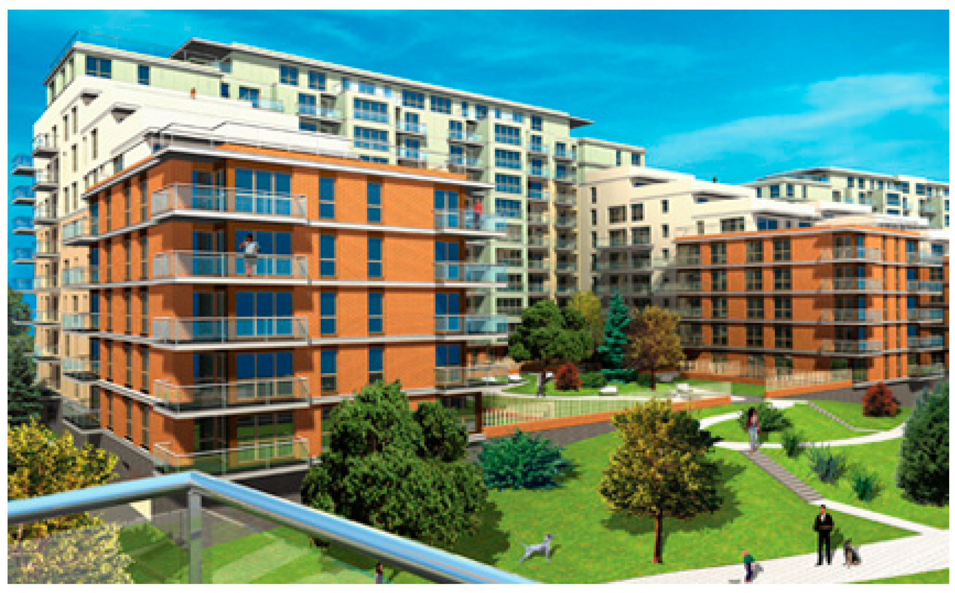
Figure 18.
Settlement on selected benchmarks (near the construction site of the “Oak Terraces” housing estate in Katowice).
Figure 18.
Settlement on selected benchmarks (near the construction site of the “Oak Terraces” housing estate in Katowice).

Figure 19.
Dependence of acceleration amplitude on the distance from the source (neighborhood of the “Oak Terraces” a housing estate in Katowice).
Figure 19.
Dependence of acceleration amplitude on the distance from the source (neighborhood of the “Oak Terraces” a housing estate in Katowice).

Figure 20.
An example of a crack was created as a result of uneven settlement of the building (at the window and under the ceiling).
Figure 20.
An example of a crack was created as a result of uneven settlement of the building (at the window and under the ceiling).


Table 1.
Frequency of measurements as part of the monitoring involving the impact on the neighborhood of tunnel construction under the roundabout in Katowice.
Table 1.
Frequency of measurements as part of the monitoring involving the impact on the neighborhood of tunnel construction under the roundabout in Katowice.
| Frequency of Measurements | |||||||
|---|---|---|---|---|---|---|---|
| Number of measurement points | During the realization of investment project | During the warranty period | |||||
| X–XII 2003 Preparation works | I–XII 2004 Execution of the diaphragm walls | I–VI 2005 Excavations | VII–XII 2005 Execution of the tunnel structure | I–X 2006 Road structure of the tunnel | to X 2008 Exploration of the tunnel | ||
| Observation of crack development | 123 | every month | every month | every month | every month | every month | II, VI, XII, XXIV month |
| Settlement Inclination | 79 10 | every month | every quarter | every quarter | every 2 months | II, VI, X month | II, VI, XII, XXIV month |
| Piezometers | 7 | every 2 weeks | every month | every month | every month | every 2 months | II, VI, XII, XXIV month |
Table 2.
Good practice rules in monitoring of structures adjacent to construction works.
| Term | The Frequency of Measurements or Observations | Documentations and Projects |
|---|---|---|
| Before construction works (at the design stage) | 1/quarter–1/half a year | Inventory of endangered objects, Inventory of existing damage, Development of a monitoring project |
| During construction works | 1/week–1/2 months (depending on the type of works and their pace) | Observation of the development of existing damage and localization of new ones Regular reports with the results of measurements and observations along with in-depth analysis |
| After completion of construction works and during operation | 1/2 months–1/year (more often during the warranty period, then less frequently, observation for a specified period given in the monitoring design) | Regular reports with the results of measurements and observations along with in-depth analysis |
Publisher’s Note: MDPI stays neutral with regard to jurisdictional claims in published maps and institutional affiliations. |
© 2021 by the author. Licensee MDPI, Basel, Switzerland. This article is an open access article distributed under the terms and conditions of the Creative Commons Attribution (CC BY) license (https://creativecommons.org/licenses/by/4.0/).
Share and Cite
MDPI and ACS Style
Łupieżowiec, M. Monitoring the Impact of the Large Building Investments on the Neighborhood. Appl. Sci. 2021, 11, 6537. https://doi.org/10.3390/app11146537
AMA Style
Łupieżowiec M. Monitoring the Impact of the Large Building Investments on the Neighborhood. Applied Sciences. 2021; 11(14):6537. https://doi.org/10.3390/app11146537
Chicago/Turabian StyleŁupieżowiec, Marian. 2021. "Monitoring the Impact of the Large Building Investments on the Neighborhood" Applied Sciences 11, no. 14: 6537. https://doi.org/10.3390/app11146537
Note that from the first issue of 2016, this journal uses article numbers instead of page numbers. See further details here.