1. Introduction
Today, total joint replacement (TJR) is a standard procedure in orthopedic surgery. Adequate osseointegration of the implant components is required for their long-term stability within the bone stock. Surface modifications such as bioactive coatings have been developed extensively to stimulate bone ongrowth, and this increases secondary implant stability [
1,
2,
3]. An alternative for the enhancement of bone ongrowth and stable implant fixation may be the application of electrical stimulation of the adjacent bone tissue. So far, in clinical practice, invasive electromagnetically induced osseotherapy has been used for the stimulation of osseoinduction in cases of avascular femoral head necrosis, femoral neck fractures, and pseudarthrosis [
4,
5]. In this therapeutic approach, based on Kraus and Lechner’s [
6] work, patients are instrumented with a bipolar induction screw implant such as the Asnis III s-series screw, (Stryker Trauma, Kiel, Germany), which consists of two electrodes and a secondary coil [
4]. A primary coil is placed around the patient’s leg during treatment, generating a low-frequency magnetic field, which transfers energy inductively to the electrical stimulation system. Sinusoidal magnetic fields in a frequency range between 12 to 20 Hz and with a voltage of 0.7 V are applied [
7]. Therefore, an alternating electric field is provided to the surrounding bone tissue. Usually, the stimulating implant is removed after three months of treatment [
4].
A retrospective clinical observation of 53 patients treated with an Asnis III s-series screw showed good postoperative results, i.e., no arthroplasty, no reoperation, and no radiological progress associated with clinical symptoms were observed in 86% of the patients with Steinberg stages I–III after 33 ± 20 months postoperatively [
7]. It has been proven by several studies that an electric field of 5–70 V/m is beneficial in order to regenerate bone tissue [
6,
8,
9,
10]. Krüger et al. [
11] proved that there was a significant influence of electromagnetic stimulation on the mechanical strength of healing bone at the ovine tibia. In a later animal study, which employed 20 dogs, an increase of 17% new bone formation compared to the control group was seen [
12]. The animals were treated with 38 Hz and 0.14 V over 8 weeks with 10 h of stimulation per day. These methods are only used for short-term regeneration of bone tissue over several months and have not been used for long-term electrostimulation of bone cells, bone tissue, or for implant stability, despite the fact that electrical stimulation can also be beneficial for THRs [
13,
14,
15]. By supporting ongrowth of bone cells at the implant surface and thereby enhancing fixation strength, revision surgery of the THR may be delayed. Furthermore, for revision implants, the stimulation of bone growth is necessary, especially in large bone defects after the removal of primary implant [
16]. Therefore, an electrostimulative acetabular revision system with additional individual patient fixations was developed [
17,
18] as there were no previously existing solutions to actively stimulate the ongrowth of bone cells on total hip stems using electromagnetic fields [
19].
In the present study, a commercially available total hip stem was instrumented in order to generate an electric field for enhanced bone regeneration in the surrounding tissue and improved ossseointegration of the implant. For this purpose, finite element simulations of the electric field distribution were conducted and validated by experimental investigations in a porcine femur as proof of concept for an instrumented electrostimulative total hip stem.
2. Materials and Methods
2.1. Modification of a Total Hip Stem
An electrode was integrated into a commercially available straight uncemented total hip stem (HIPSTARV40, Stryker, Duisburg, Germany) made from titanium alloy. For this, the implant was modified by milling a notch into its anterior side. The depth of the notch was 1.5 mm, which was decided based on a static analysis of the implant strength. A width of 3 mm was determined to allow for adequate insulation between the first electrode (Ti6Al4V wire) and the second electrode (total hip stem). The insulating material was made from zirconium oxide (ZrO2), which is a biocompatible ceramic, primarily employed in the field of dentistry.
The Ti6Al4V wire and the insulator were adapted to critical regions of bone ongrowth of straight total hip stems. Clinically, sufficient ongrowth of bone tissue is observed at the lateral and medial parts of the central and distal areas of straight stems [
20]. In particular, radiolucent lines are observed at the proximal part, which indicates a lack of bone ongrowth in this implant area. Due to this reason, the notch was positioned in such a manner so as to stimulate in particular the anterior and posterior parts in the proximal and central areas to achieve an additional effect on bone ongrowth by the electric stimulation. The electrodes were supplied by an alternating voltage to allow an electrical field to subsist around the implant. The alternating voltage also facilitated the usage of an inductively coupled system during the clinical application, thus avoiding the need for an internal power source. The energy was transferred by an alternating magnetic field generated by an external coil that was supplied by an external power source.
2.2. Reconstruction of the Femur
The geometrical structure of the porcine femur was arranged according to the work in [
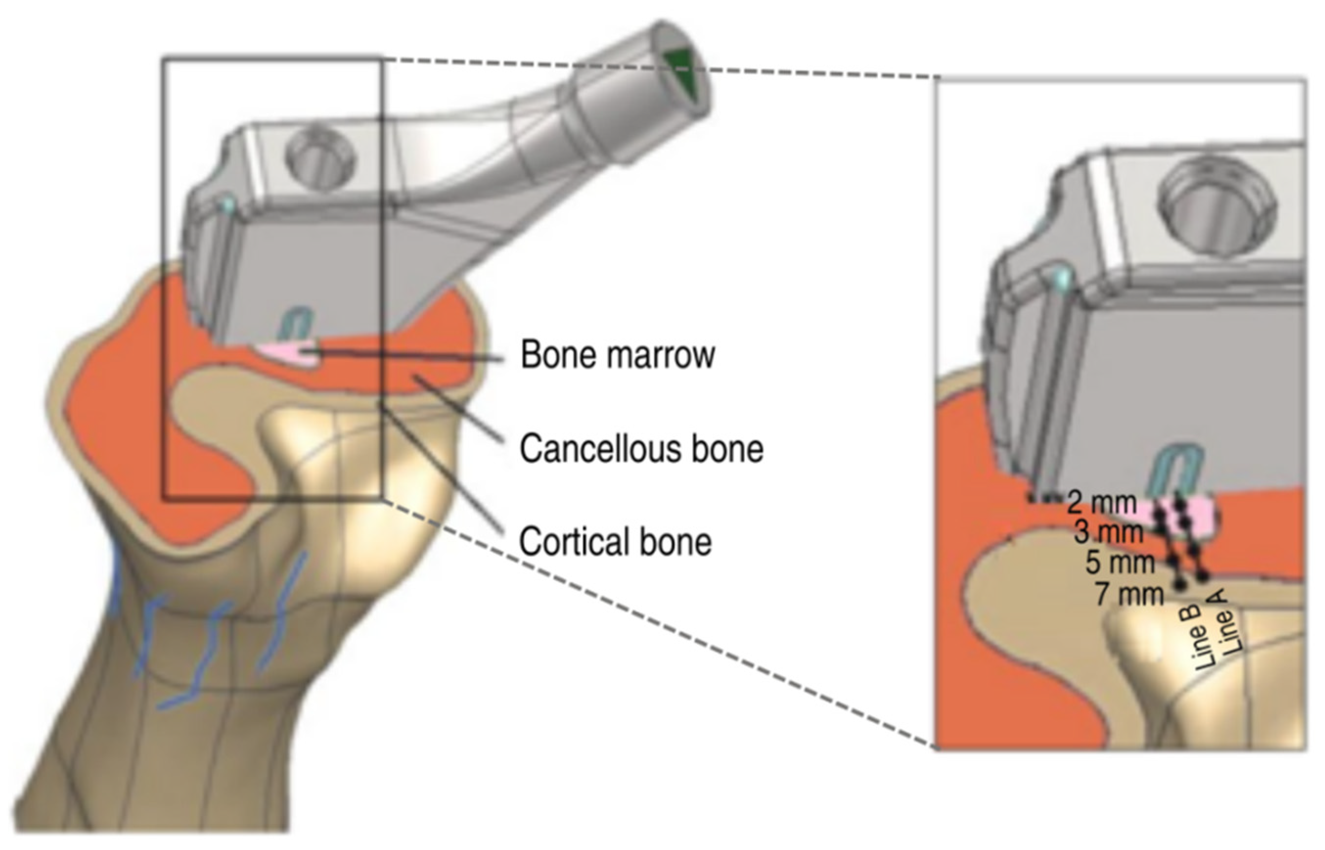
21]. To this end, CT scans of the femur were created and manually segmented according to their Hounsfield Units (HU) using Amira software (FEI, Burlington, MA, USA) as cortical bone, cancellous bone, and bone afmarrow (see
Figure 1). All tissues were converted to stereolithography (STL) files in American Standard Code for Information Interchange (ASCII) format. Subsequently, these STL files were transferred to the reverse engineering software Geomagic (Geomagic, Stadt, NC, USA) to generate and refine the nonuniform rational Bspline (NURBS) computer-aided design (CAD) models for simulation.
2.3. Numerical Simulations
The simulations were performed using commercial software SIMULIA CST Studio Suite (Dassault Systèmes,
www.3ds.com/simulia, accessed on 10 May 2021), and the electric field within the femur model was computed. Here, the specific solver used was based on the Finite Integration Technique (FIT). The assembly of the computational domain was based on the reconstruction of the femur and the CAD model of the hip stem. Both were fitted into the numerical model, with the coordinates being taken by the coordinate measuring arm of the experimental setup for the sake of better comparison of computed and measured results.
The dielectric properties of the different tissues (bone marrow, cancellous bone, and cortical bone) were defined using the parameters from Gabriel et al. [
22] and Hasgall et al. [
23] as provided for human bone as no data were available for the porcine bone. It had to be assumed, though, that the dielectric properties of the adolescent porcine bone tissues differ from adult human bone tissues. This simulation is referred to as case study 1. Because of the almost insulating properties of the bone marrow when using parameters from Gabriel et al. [
22], a second simulation was performed using the conductivity of the cancellous bone within the domain of the bone marrow. This simulation is referred to as case study 2. Furthermore, case study 3 was performed using the parameters from Hasgall et al. [
23] but with red bone marrow. As the electric conductivity of titanium is considerably higher than that of the biological tissue, a Perfect Electric Conductor (PEC) could be used rather than including titanium into the computational domain, which reduced the computational effort. Conversely, the insulator has a considerably lower conductivity compared to the biological tissue. Due to this reason, it was defined as a perfect electric insulator (a vacuum).
The electric double layer, which exists at the interface between electrodes and organic tissue, as well as between the implant surface and organic tissue, was characterized by its impedance
Z based on the approximate formula below using measured data of its surface
A along with the impedance
ZSample measured for a sample electrode with the surface
ASample.
Using this approximation, an impedance of 3 kΩ at the electrode and 120 Ω at the hip stem was calculated. After the first simulation, the determination of the impedance of the bone sample got possible. For the dielectric tissue parameters as proposed by Gabriel et al. [
22], the resultant impedance was 13.25 kΩ. To consider the effects of the double layer, its impedances were considered in a serial connection with the impedance of the organic tissue. Using the equation
the boundary conditions for the simulation were reset to 0.044 V instead of 0.000 V at the hip stem and 4.900 V instead of 6.000 V at the electrode.
The problem was discretized on a hexahedral mesh in conjunction with the Enhanced Fast Perfect Boundary Approximation (EFPBA), which provided an accurate geometrical approximation of the continuous structure. In particular, the mesh around the electrode and the insulator was enhanced to ensure an optimal resolution in the area of interest. The mesh around the readout locations was also densified to avoid interpolation errors. During the first simulations, the adaptive mesh refinement was used to improve the hexahedral mesh automatically. As a result of the convergence study, the final mesh consisted of approximately 9.55 million mesh cells.
Due to the relatively low applied frequency, the capacitive properties of the biological tissues could be neglected. For this reason, the stationary current solver of CST EM STUDIO® was used. Prior tests revealed that the error, created by the simplification, was below 0.5% compared to the quasistatic solutions, while computation time was reduced drastically. The computation time for a solver accuracy of 1·10−9 of the linear solver was less than 10 min when a workstation computer (4 × 2.53 GHz, 12 GB RAM) was used. The electric fields caused by the voltage of the experiment were considerably higher than the proposed maximum field strength of 70 V/m. This was due to the supply voltage of 6 V during the experiment that was selected to simplify the measurement and to minimize measurement errors. In order to compare the simulated distribution of the electric field during the experiment with the proposed electric field during the clinical situation, further simulations were performed using the proposed supply voltage of 0.2 V.
2.4. Experimental Setup
To prove the numerical simulation’s accuracy, a validation experiment was set up according to the clinical application. Therefore, the instrumented total hip stem was inserted into a porcine femur. For this, the femoral head was cut and a borehole (Ø 12 mm) was drilled along the axis of the femur. The bone stock was carefully prepared with rasps. Using a hammer, the total hip stem was inserted into a press-fit fixation in order to allow close contact with the surrounding bone tissue. The wire that connected the first electrode was led through the porcine femur to the power supply. The total hip stem was also connected to the power supply (Agilent 33220A, Agilent Technologies Inc., Colorado Springs, CO, USA).
A three-dimensional (3D) coordinate measuring arm (MicroScribe G2x, Solution Technologies, Oella, MD, USA) was used to determine the coordinates of the readout locations, which were maintained as consistent in the numerical simulations. The function generator supplied an alternating field (20 Hz, 6 V). Before the total hip stem was implanted into the bone, the root mean square (RMS) voltage on the surface of the hip stem was measured using a multimeter. This value was used as a boundary value on the hip stem in the numerical simulation in order to compare the data with the experiment. The potential on the surface of the cross section of the bone was measured at different points along two lines perpendicular to the electrode and to the interface between the insulator and the stem. The points measured were at distances of 2, 3, 5, and 7 mm (
Figure 1) along these two lines.
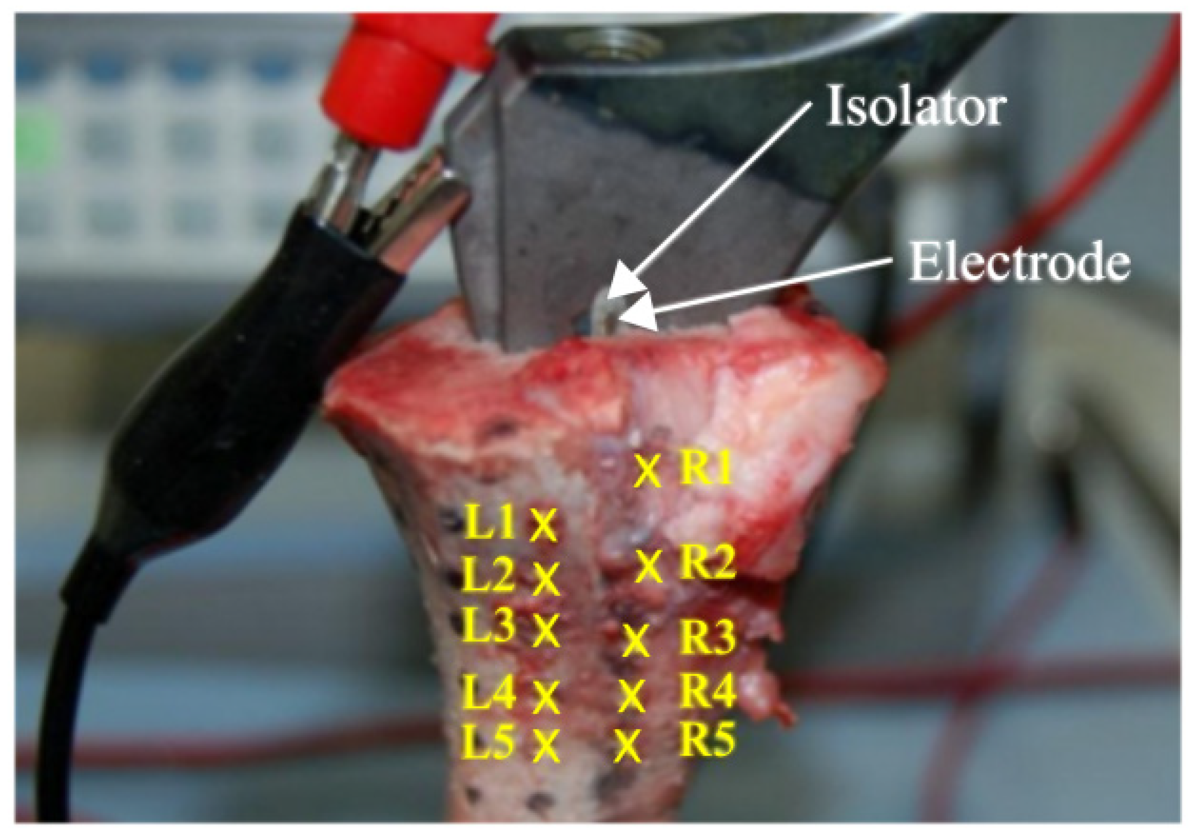
A raster of 10 different points (readout locations) at a distance of 10 mm was marked at the surface of the frontal femur (
Figure 2). The electric potential was measured for all points of the raster at approximately 5 mm and 8 mm depth into the bone. This measurement was performed in triplicate. During measurements, the bone tissue was rehydrated with an NaCl solution (conductivity of about 1.5 S/m) to minimize the influence of dehydration of the specimen.
3. Results
The results of the measurements on the cross section of the porcine femur perpendicular to the first electrode and the interface between the insulator and the implant have been shown in
Table 1. As in a homogeneous medium the electric potential varies inversely proportional with the distance from the electrode, it could be roughly expected that measurements on line B starting from the interface between the implant and the insulator resulted in smaller values of the potential than measurements on line A starting from the first electrode. This holds true except for the measured values at a distance of 7 mm. The distinctive distribution of the electric potential demonstrates that the highest values of 1.68 V, 1.25 V, and 1.17 V (case studies 1–3) were obtained on line A. The investigation of the potential at the cross section of the bone resulted in a decay of 78% on line A (2–7 mm) and 72% on line B. In case study 1, the decay amounted to 68% along line A. For case study 2, it was 53% and for case study 3, it was 46%. In general, case study 3 came closest to the measured values, with deviations in the range of 0.01 V–0.25 V. Regarding the differences in measured and simulated potential values, one should keep in mind that there are several error sources both in measurements as well as in the numerical simulations. The most important error source in the simulations has to be attributed to the lack of data on dielectric tissue properties for porcine bone which is why the data from human bone needed to be taken. Additionally, there is rather high uncertainty in general in dielectric tissue properties in the low-frequency spectrum.
The distribution of the electric field strength and the electric potential in the numerical simulation shows a strong stimulation capacity of the surrounding bone tissue (
Figure 3 and
Figure 4). The implant surface is also stimulated. When the tissue properties from Gabriel et al. [
22] for yellow bone marrow were used, its insulating effect on the electric field distribution became evident (see
Figure 3a). In the case of using higher conductivity as of red bone marrow [
23], the electric field reached a larger area of the surrounding bone and was more evenly distributed (see
Figure 3b).
In case studies 2 and 3, the electric potential at the raster displays the same trend due to the similar potential values of red bone marrow and cancellous bone (
Figure 4). Moreover, for both simulation studies, the potential at the left side of the raster, i.e., readout locations L1–L5, is closer to the experimental values compared to case study 1. The highest experimental value for the electric potential was measured at readout location L4 and showed high standard deviation (
Figure 4b).
According to the measurements at the cross section of the porcine femur, case study 3 (
Figure 5) showed the overall best agreement with the experiment. As displayed in
Figure 4a, deviations were observed in the range of 1 to 25% at 5 mm depth between case study 3 and the experimental results. At 8 mm depth, deviations were within 1–41%, except for readout location L4, as obvious from
Figure 4b. In the sequel, case study 3 was compared to the simulation with 0.2 V (
Figure 5b) supply under clinical conditions because of the overall better approximation compared to the other two case studies.
4. Discussion
In the present study, we investigated the general feasibility of an electrostimulative uncemented total hip stem. The bone, being in close proximity to the implant, provides most of the mechanical stability. For this reason, the area close to the implant is of highest interest and thus the electrical stimulation can be limited to the closest bone on both sides of the implant. Therefore, the electric potential values at the cross section of a porcine femur and along a defined raster along the porcine femur defined at depths of 5 mm and 8 mm into the bone were measured in an experiment and compared to results from three different numerical simulation scenarios. Based on two different conductivity values for bone marrow, three case studies were performed in order to discover the most precise model to replicate the physiological behavior of the bone. In the first simulation scenario (case study 1), yellow bone marrow was simulated with low conductivity [
22]. The second simulation scenario (case study 2) excluded bone marrow by replacing it with cancellous bone, and the third simulation scenario (case study 3) worked with data from Hasgall et al. [
23], including red bone marrow. In our survey, it was found that case study 3 represented the best approximation to the validation experiment performed. In this case study [
24], the predicted potential (see
Table 1) was in good agreement with our experimentally measured values at the cross section of the porcine femur, thus supporting our assumption of electric field distribution with the bone tissue. In this context, a closer investigation of the influence of tissue conductivity on the electric field distribution of the electrostimulative total hip revision system has been performed [
24].
As the electric properties of biological tissues behave linearly at a fixed frequency, the factor used to decrease the stimulation voltage can also be used to decrease the electric field. During the experiment, the primary goal was to generate a high potential to achieve a value several magnitudes above the error tolerance of the multimeter. This resulted in high gradients of the potential and the electric field as can be observed in
Figure 5a. For clinical use, the electric fields for bone regeneration are required to be between 5 and 70 V/m [
6]. In this first approach, a voltage of 0.2 V was selected to achieve the desired electric field strengths. The yellow and red area in
Figure 5a can be considered over-stimulated (>70 V/m). This area had to be minimized, which means that the voltage had to be reduced. In contrast, the dark blue area in
Figure 5b was not stimulated sufficiently (<5 V/m), and to minimize this area, the stimulation voltage had to be increased. Both these contradictory goals can be accomplished without changes in the voltage by slightly increasing the width of the insulator [
25].
A limitation of our experiments was given by the high standard deviations of the measured potential. These were likely due to the drying out and rehydration processes performed during measurements. Another reason for the deviations is the use of bone tissue from adolescent pig, which does not have the same dielectric properties as an adult human bone tissue [
26].
Figure 4 and
Figure 5 show that apart from readout location L4 at 8 mm depth, the values of the simulation were close to the measured potential in the experiment. The outlier behavior of readout location L4, which had a 99% (depth 8 mm) deviation from simulations 2 and 3, necessitates an investigation of the boundary conditions of the experiment. Due to this reason, the relevant CT scan at the height of L4 was examined in detail. The dark areas within the cancellous bone and marrow are fluids, which increases the conductivity significantly at these locations. As the CT scan was performed prior to the implantation of the stem, the position of these fluids may have changed during the implantation. The fluids may have also affected the potentials at readout locations L3 and L5. This effect was not confirmed in measurements at readout locations near the boundary between cortical and cancellous bone at a depth of 5 mm.
A further limitation of the study was the model of the electric double layer, used for the simulation. This is a simplification of the passivation layer of the titanium. The relatively high voltage of 6 V compared to the desired clinical application was induced directly and was used because of a simplified measurement setup. Furthermore, the stationary current solver of CST EM STUDIO® was used to calculate the electric potential and electric field strength in all tissues. In clinical studies, a frequency of 20 Hz is used. Analytically, the maximum error using the stationary current solver instead of the electro-quasistatic solver is below 6%. This is due to the low stimulation frequency. Earlier studies comparing the stationary solver with the electro-quasistatic solver showed deviations below 0.5%. Higher deviations are possible due to the uncertainty and minor local changes in the dielectric tissue properties. Therefore, the stationary current solver was used.
An additional limitation was the conductivity values used for this work. In other studies [
22,
27], bovine, canine, and human tissues were considered, which showed different tissue properties [
23]. These variations may also be the reason for deviations in the generated electric fields. Other simplifications of the model were the use of perfect electric conductors instead of titanium and the use of perfect insulators instead of ZrO
2. As the electric conductivity of the bone was within a magnitude of 0.01 S/m, the error introduced by this idealization may well be assumed to be insignificant. The coordinates measured with the coordinate-measuring arm were another source of error as the measurement device offers limited accuracy and because some of the coordinates were measured on top of moderately soft tissue, which could have been neglected during the segmentation process. The absolute coordinates were used to define the position of the bone and implant for the numerical model. However, the maximal deviation of these measurement points and the supposed point on the surface of the CAD model was 0.27 mm.
In future studies, the size of the insulator and electrode as well as the number of electrodes should be optimized numerically to achieve electric field strengths between 5 and 70 V/m, without affecting the mechanical requirements of the total hip stem. In comparison to the electromagnetic stimulation in osseotherapy [
6], the electrodes at the implant can be assembled horizontally. The arrangement differs from the systems currently used in osseotherapy, as it employs parallel electrodes [
7]. The application of only electric fields and electric potentials could be realized by the use of an intelligent implant that provides the power supply.


 ,
, 


