Article

Effect of Configuration and Yield Strength of Transverse Reinforcement on Lateral Confinement of RC Columns

1
Land & Housing Institute, Korea Land & Housing Corporation, 539, Expo-ro, Yuseong, Daejeon 34047, Korea
2
Department of Architectural Engineering, Kongju National University, 1223-24, Cheonandaero, Seobuk, Cheonan 31080, Korea
3
Department of Fire Protection Engineering, Sangji University, 83 Sangjidae-gil, Wonju 26339, Korea
*
Author to whom correspondence should be addressed.
Appl. Sci. 2021, 11(15), 6696; https://doi.org/10.3390/app11156696
Submission received: 15 June 2021 / Revised: 7 July 2021 / Accepted: 16 July 2021 / Published: 21 July 2021

Abstract

:
In general, the lateral confinement capacity of RC columns is influenced by the strength and configuration of transverse reinforcement. In this study, performed antisymmetric flexural moment experiments that simulated seismic loads, with the configuration and yield strength of the transverse reinforcement of RC square columns as main variables. The eight specimens were square cross-sections measuring 250 × 250 mm, and the lateral confinement effect in relation to main variables was examined by inducing flexural failure in the plastic hinge zone under a shear span-to-depth ratio (a/D) of 3.0. Transverse reinforcements comprised a square and octagonal S-series and tie-based H-series. The yield strengths of the transverse reinforcements were 453 MPa and 1053 MPa, respectively. Compared to the H-series, the S-series, whose configuration of transverse reinforcement is closer to a circular form, exhibited more prominent ductile behavior after flexural yield with increasing yield strength of transverse reinforcement, which indicates greater lateral confinement.

1. Introduction

RC members designed to undergo flexural failure will develop a plastic hinge at the critical section, located away from the end of a member by a length corresponding to the effective depth (d), when the longitudinal reinforcement experiences flexural yield under repeated loads like seismic loads. According to past research, flexural RC members, exhibit ductile behavior through moment redistribution after plastic hinge formation [1,2,3]. However, they may not engage in ductile behavior if concrete undergoes compressive failure due to insufficient lateral confinement at the critical section, located away from the end by a length corresponding to the effective depth (d).
The ductile behavior of RC columns, which are subject to axial force, is dominantly influenced by the lateral confinement effect of concrete near the plastic hinge zone. Proper lateral confinement of RC members by transverse reinforcement will prevent buckling of longitudinal reinforcement and, at the same time, ensure effective moment redistribution [4,5,6,7].
Past studies have showed that the lateral confinement capacity of columns is influenced by the amount and configuration of transverse reinforcement surrounding the core concrete, and by the yield strength, with circular cross-sections having better lateral confinement than square cross-sections [8,9,10,11,12]. However, columns are usually designed to have square cross-sections to enable joining with beams, and for more convenient longitudinal reinforcement configuration at the column-beam joints. While RC members with circular cross-sections can provide lateral confinement to the core concrete using hoop reinforcement, square cross-sections provide lateral confinement to the core using square ties for an arrangement of longitudinal reinforcement. However, the square tie will only have the central part of the square column to be laterally confined, thus reducing the lateral confinement effect. Buckling of longitudinal reinforcement occurs under axial force and lateral force, and this in turn results in brittle failure [13]. As such, there have been many cases of columns with square ties being destroyed in earthquakes.
Extensive research has been conducted on transverse reinforcement configuration of square RC columns from the 1980s to the early 2000s. Studies have confirmed that transverse reinforcement with more circular shapes has increased lateral confinement capacity. [14,15,16,17,18]. According to a study of Samra et al. in 1996 [19], it has been reported that spiral transverse reinforcements can improve the strength and ductility of RC columns, and the need for research on spiral transverse reinforcement applicable to square cross-sections has been highlighted.
In past research, the authors of this study developed spiral transverse reinforcement with alternating squares and octagons for use in square RC columns [20]. Compared to existing ties, spiral transverse reinforcement not only improves constructability and lowers costs, but also offers excellent structural performance. However, more systematic research is needed on the yield strength and axial force ratio, which are key factors affecting lateral confinement capacity.
This study presents the results of performed experiments with the configuration of transverse reinforcement, yield strength of transverse reinforcement, and axial force ratio as main variables to assess the lateral confinement performance of spiral transverse reinforcement, comprised of alternating squares and octagons, designed to be close to a circular shape. Based on the experimental results, the effects of yield strength and reinforcement configuration on lateral confinement were evaluated, and the relationship between main variables and ductile behavior was examined.

2. Experimental Plan

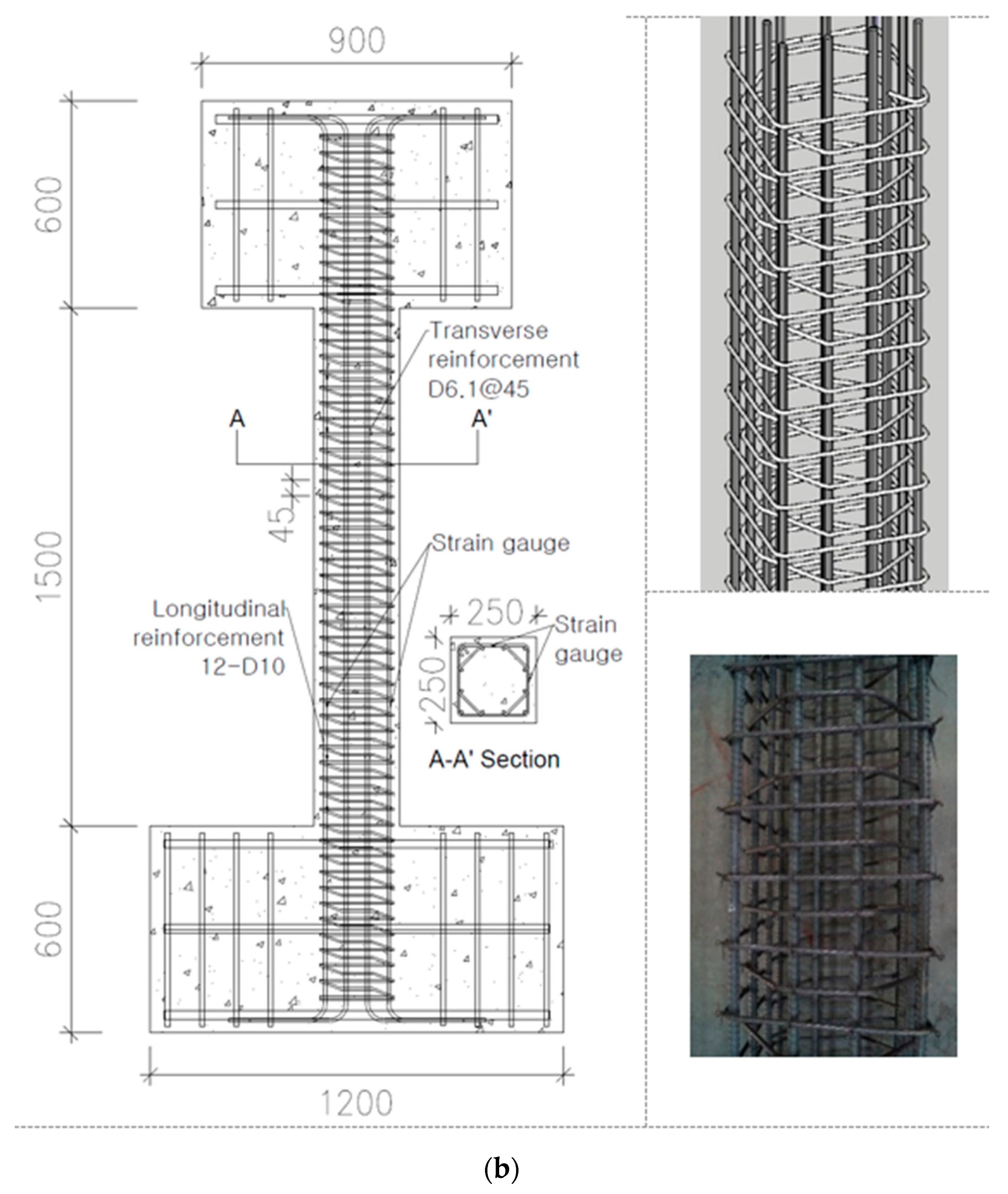
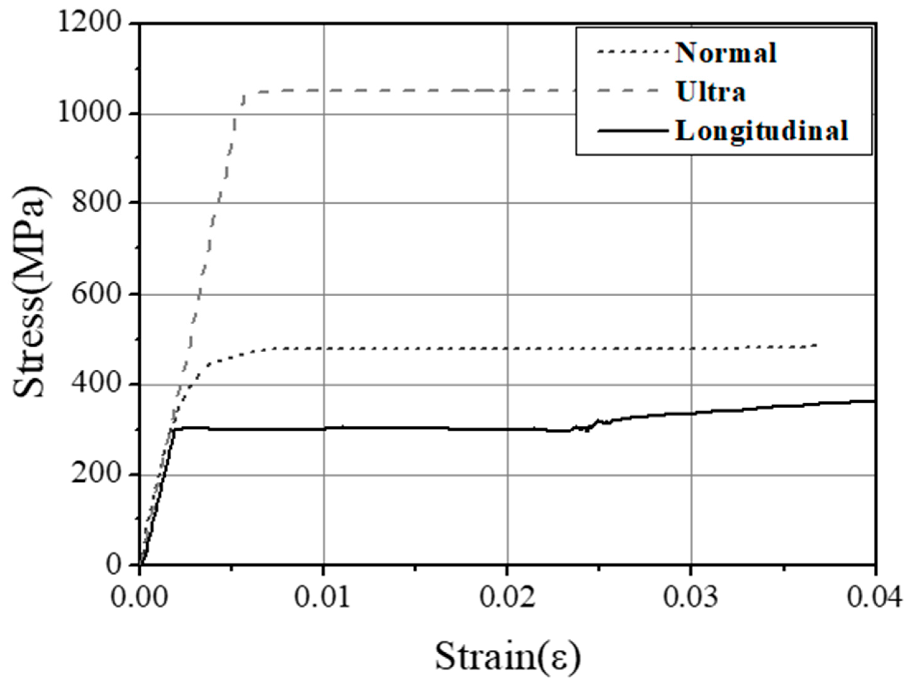
Figure 1 and Table 1 show the fabricated eight RC column specimens having stubs at the ends. The main variables were configuration of transverse reinforcement (tie: H-series, spiral reinforcement: S-series), yield strength of transverse reinforcement (Normal: 453 MPa, Ultra: 1053 MPa), and axial force ratio (20%, 30%). The specimens were named in the form of NH20 (example), as shown in Figure 2. Here, N is the yield strength of transverse reinforcement, H is the transverse reinforcement of ties, and 20 represents an axial force ratio of 20%.
The concrete used to fabricate the specimens had a compressive strength of 35 MPa; the longitudinal reinforcement was 12-D10 (71.3 mm2) with a yield strength of 300 MPa. The transverse reinforcement used in specimens was D6.1 (28.27 mm2) regardless of configuration, and the yield strengths of the transverse reinforcement were 453 MPa and 1053 MPa, respectively, as shown in Figure 3.
As shown in Figure 1, the square cross-sections measure 250 × 250 mm, and the height of the experimental section was set as 1500 mm for a shear span-to-depth ratio (a/D) of 3.0. The H-series were spaced at 63.3 mm intervals in the experimental region, and the S-series were spaced 45.3 mm intervals. The total length of transverse reinforcement per spacing was 1680 mm for the H-series, and 745 mm for the S-series. That is, the S-series had 55% less transverse reinforcement.
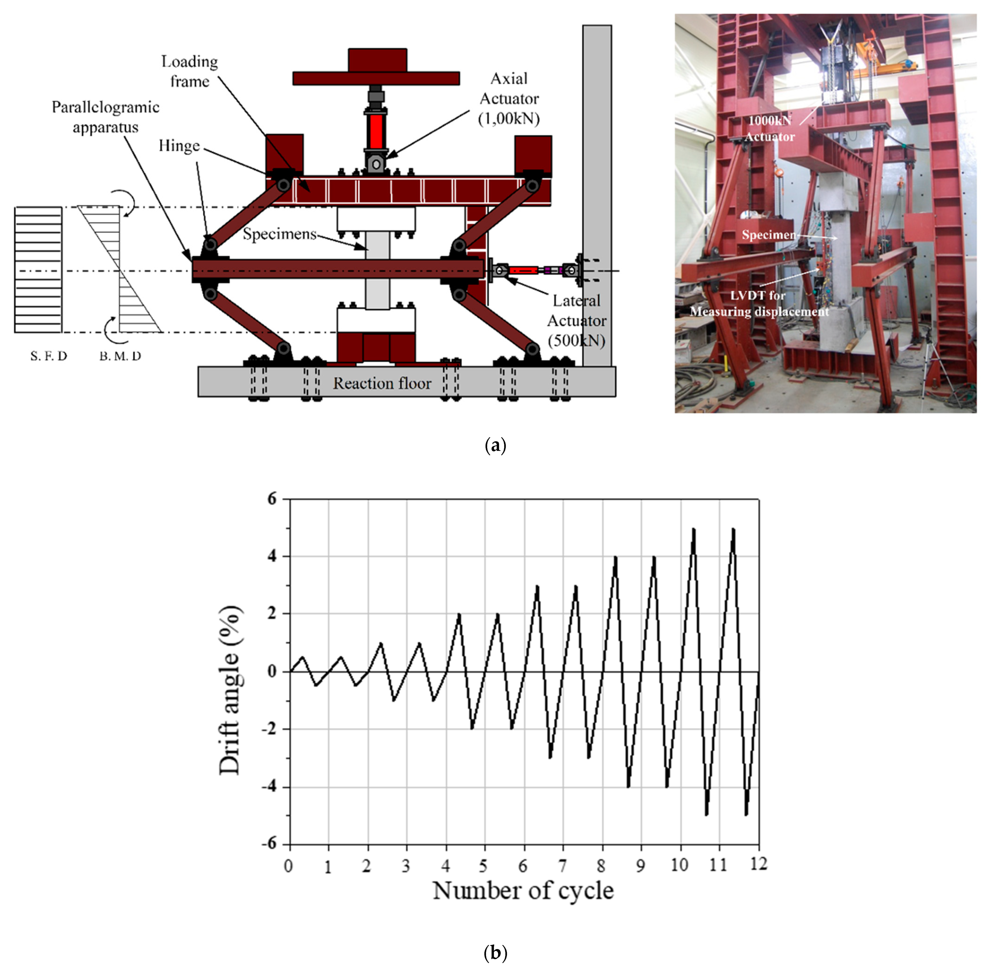
The loading was designed with an antisymmetric flexural moment to simulate seismic loads. A constant axial load was applied using an actuator of 1000 kN capacity, as shown in Figure 4a, and lateral load was applied twice according to the drift angle using an actuator of 500 kN capacity, as shown in Figure 4b.
The drift angle was calculated based on displacement ( Δ y ) of specimens at the time of yield of longitudinal reinforcement. As shown in Figure 4c, the displacement according to the lateral load of specimens was measured from the average of an LVDT with a range of 200 mm installed symmetrically at the mid-height of the specimen. A strain gauge was attached, as shown in Figure 1, to measure the longitudinal reinforcement and transverse reinforcement of specimens.

3. Experimental Results

3.1. Relationship of Lateral Load-Drift Angle

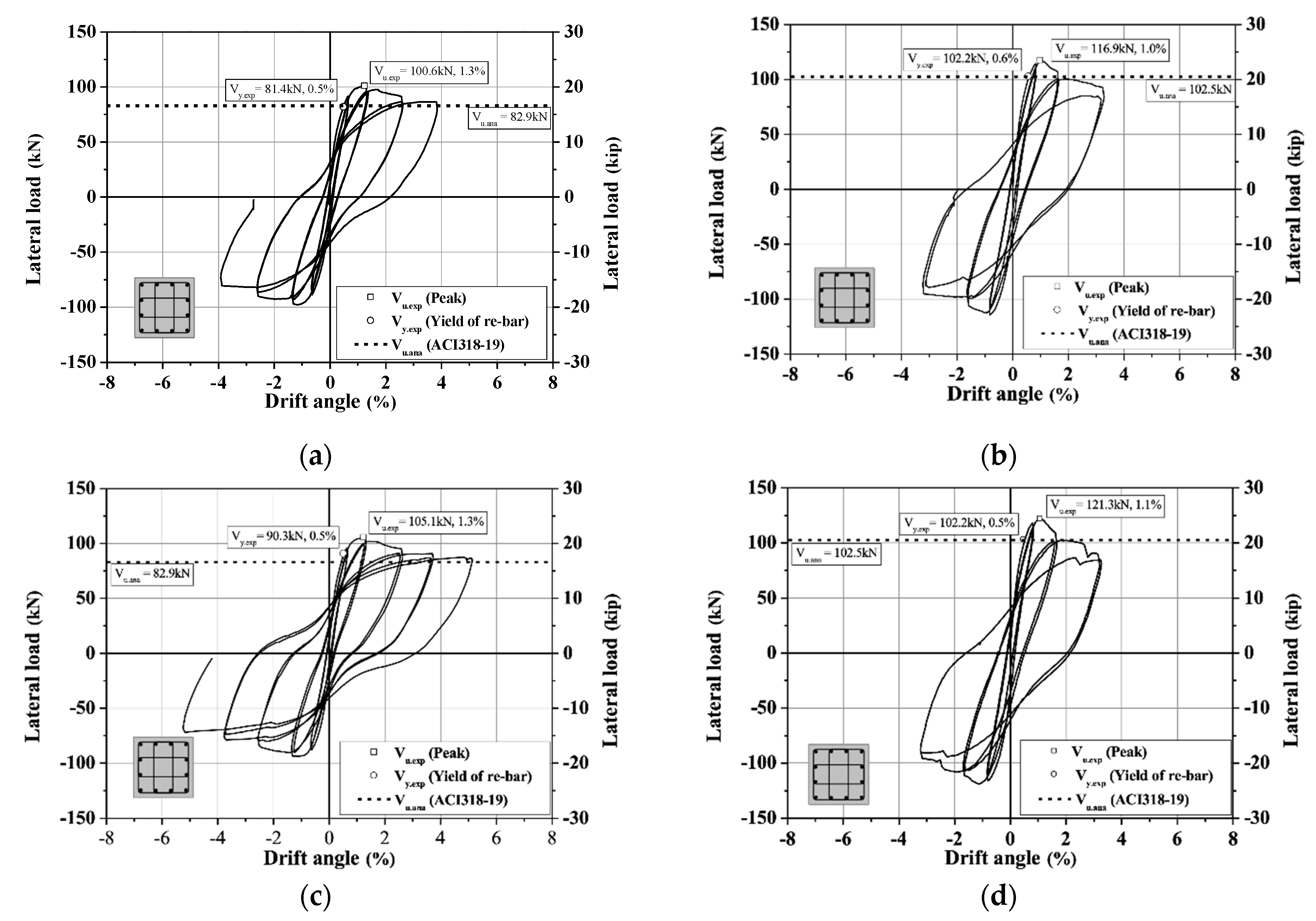
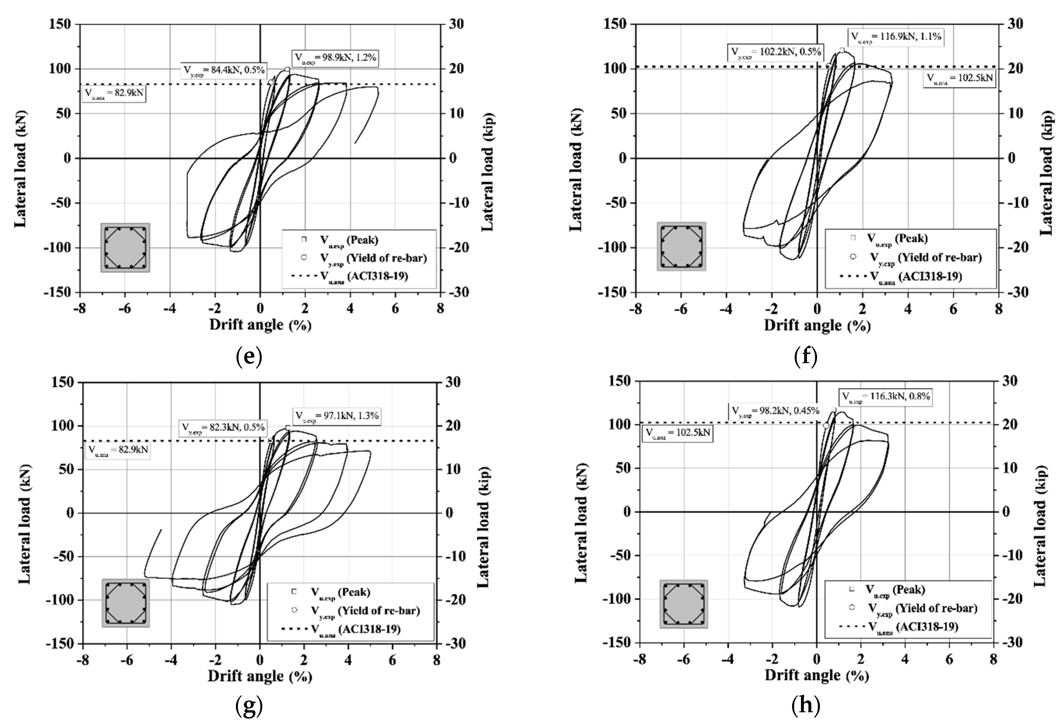
Figure 5 shows the relationship of lateral load-drift angle of specimens based on the experimental results. As shown in Figure 5, the longitudinal reinforcement of the H-series specimens experienced flexural yield at a drift angle of 0.5% regardless of the axial force ratio or yield strength of transverse reinforcement. Specimens with an axial force ratio of 30% had a higher yield load compared to those with an axial force ratio of 20%, but the change in initial flexural rigidity was not large. The yield strength of transverse reinforcement did not cause significant differences in flexural yield load. The peak load of specimens was high when the axial force ratio increased from 20 to 30%, but the difference due to yield strength of transverse reinforcement was not significant. Regardless of yield strength, after reaching the peak load, specimens with an axial force ratio of 30% showed a rapid decrease in strength compared to those with an axial force ratio of 20%.
Similar to H-series specimens, S-series specimens underwent flexural yield of longitudinal reinforcement at a drift angle of 0.5%. The yield load of specimens increased with axial force ratio, but was not significantly influenced by yield strength of transverse reinforcement. The peak load of specimens increased with axial force ratio, but was not influenced by yield strength of transverse reinforcement. The difference in yield strength according to transverse reinforcement configuration averaged around 3%, while peak load differed by only about 4%. As shown in Figure 5, the rigidity of yield load and failure of specimens after reaching the peak load were similar regardless of configuration of transverse reinforcement.

3.2. Crack Patterns and Failure Shapes

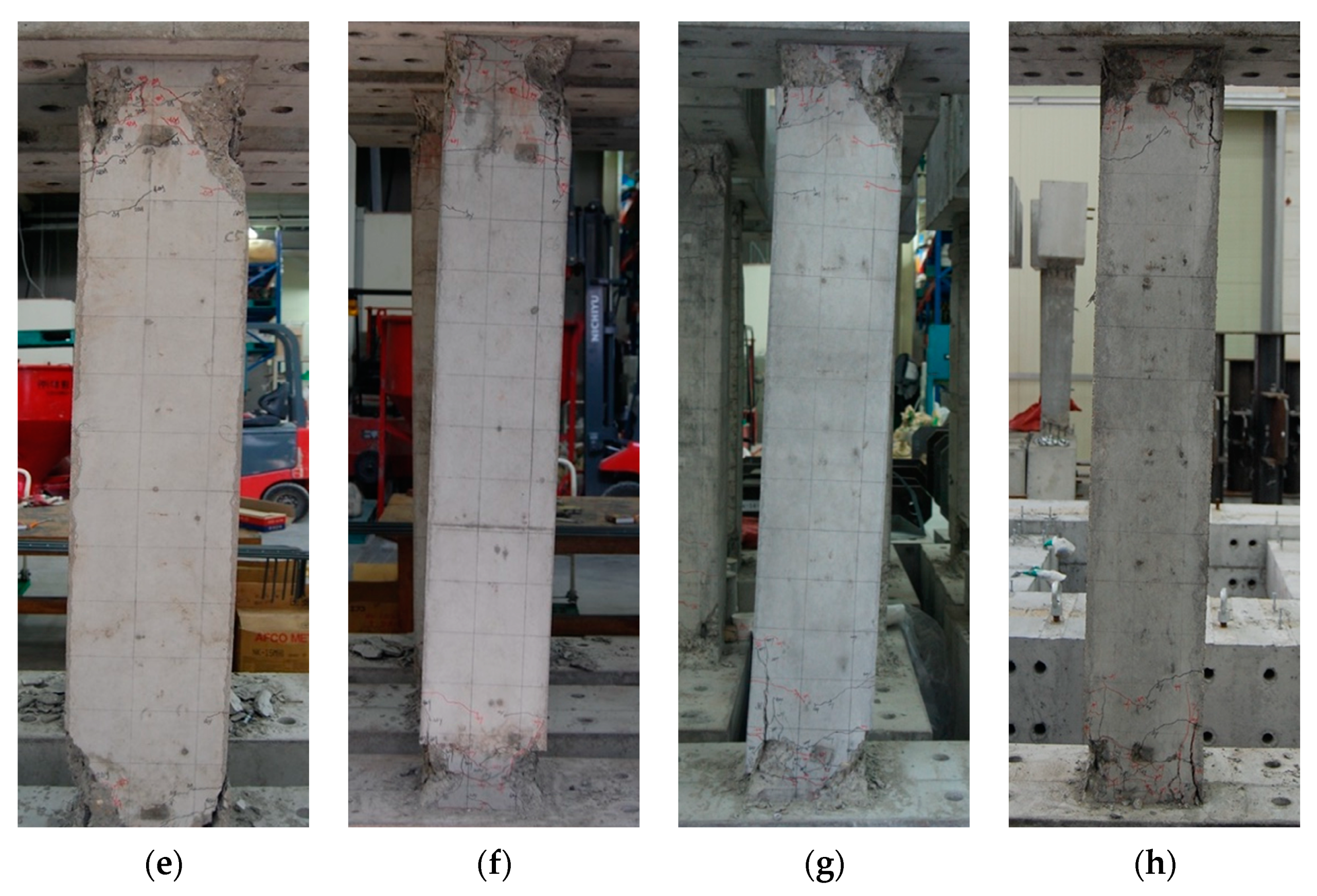
As shown in Figure 6, all specimens developed a plastic hinge in the critical section, located away from the end at a length corresponding to the effective depth (d), and exhibited typical flexural failure caused by concrete peeling. Delamination after concrete crushing at both ends of the critical section was prominent in H-series specimens, but axial force ratio did not result in significant differences in failure behavior. In particular, the H-series specimens showed buckling of longitudinal reinforcement in the plastic hinge zone, and loosening of sub-ties used for lateral confinement of longitudinal reinforcement within cross-sections. The S-series specimens did not have buckling of longitudinal reinforcement in the plastic hinge zone, and provided more effective lateral confinement to longitudinal reinforcement and core concrete compared to the ties used in the H-series.

4. Analysis of Experimental Results

4.1. Strain Distribution in the Reinforcement

In this study, the failure behavior of the specimen was analyzed using the strain distribution of strain gauges attached to the longitudinal and transverse reinforcement. Figure 7 shows the strain distributions of longitudinal reinforcement in relation to lateral load. Regardless of yield strength of transverse reinforcement, configuration of transverse reinforcement, and axial force ratio, all longitudinal reinforcement of specimens experienced yield at the critical section (d = 250 mm) of both ends under a drift angle in the range of 0.45 to 0.6%. After reaching the peak load, the strain of longitudinal reinforcement increased at the critical section, which indicates plastic hinge formation at both ends of the critical section.
Although the configuration and yield strength of transverse reinforcement did not influence strain distribution of longitudinal reinforcement, longitudinal reinforcement showed greater strain in the plastic hinge zone with increasing axial force ratio.
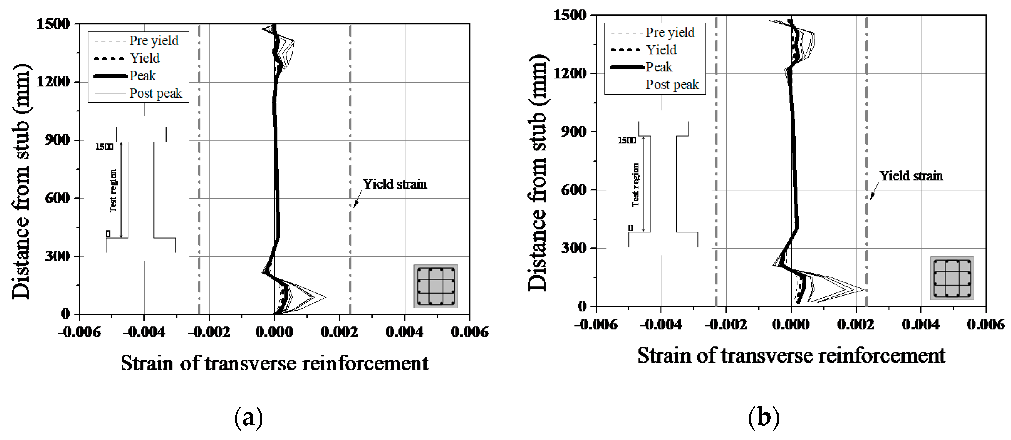
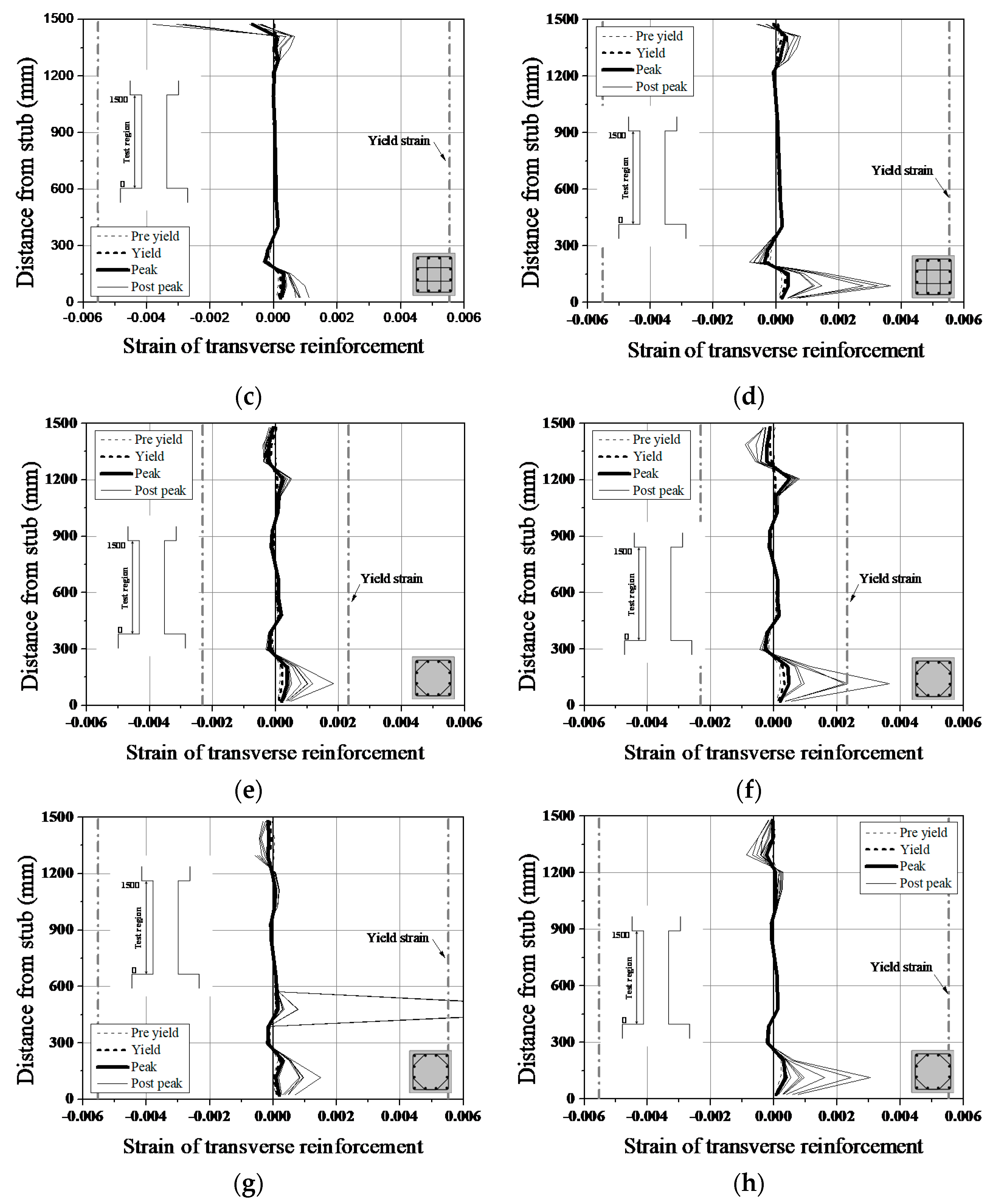
Figure 8 shows the strain distribution of transverse reinforcement in relation to lateral load. Regardless of yield strength of transverse reinforcement, configuration of transverse reinforcement, and axial force ratio, the transverse reinforcement of all specimens did not experience yield before reaching the peak load. Transverse reinforcement strain was more prominent at the critical section, where the plastic hinge develops, than the center of specimens. As a result, flexural failure occurred at the critical section due to the yielding of longitudinal reinforcement at the critical section.
All specimens showed greater strain of transverse reinforcement at the critical section with higher axial force ratio. Compared to the H-series, the S-series specimens exhibited greater strain of transverse reinforcement at the critical section with higher yield strength of transverse reinforcement and axial force ratio. In particular, the transverse reinforcement of NS30 specimen experienced yield after the peak load. The proposed spiral transverse reinforcement with alternating squares and octagons was thus verified as providing effective lateral confinement within the critical section even under high axial force ratio, and lateral confinement grew more pronounced with increasing yield strength of transverse reinforcement.

4.2. Flexural Strength and Ductility

To test the reliability of the experimental results, this study compared the maximum flexural strength of specimens to the ACI318-19 code [21]. The equation from ACI318-19 is as follows.
M n = P n · e = 0.85 a b ( h 2 a 2 ) + i = 1 n ( A s i f y ) ( h 2 d i )
As shown in Table 2, the maximum flexural strength of specimens was, on average, 1.8 times the flexural strength of specimens predicted based on ACI318-19, and the coefficient of variation was approximately 3%, thus demonstrating the reliability of the experimental results. The configuration of transverse reinforcement, axial force ratio, and yield strength of transverse reinforcement did not affect the comparison between experimental results and analysis.
This study calculated curvature at yield and maximum flexural strength using Equation (2) [22]. The curvature of specimens was obtained from the strain gauge bonded to the critical sections.
ϕ = ε s c + ε s t d
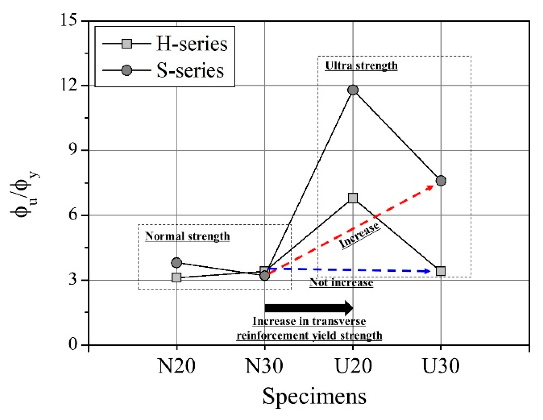
As shown in Table 2 and Figure 9, the curvature ductility factor of specimens ( ϕ u / ϕ y ) was 1.1 to 2.2 times higher for the S-series than for the H-series, with the exception of US20. Here, ϕy represents the curvature ductility at yield of longitudinal tension reinforcement, and ϕu is the curvature ductility at flexural failure. The difference in curvature ductility factor in relation to configuration of transverse reinforcement was larger at higher axial force ratio, and the curvature ductility factor of US30, with high-strength transverse reinforcement, was 2.2 times greater than that of UH30. Compared to the H-series, the proposed S-series transverse reinforcement was thus found to exhibit outstanding ductility due to effective lateral confinement of core concrete and longitudinal reinforcement under high axial force, except the NS30 specimen. Such ductile behavior improved with increasing yield strength of transverse reinforcement.

4.3. Plastic Hinge Length

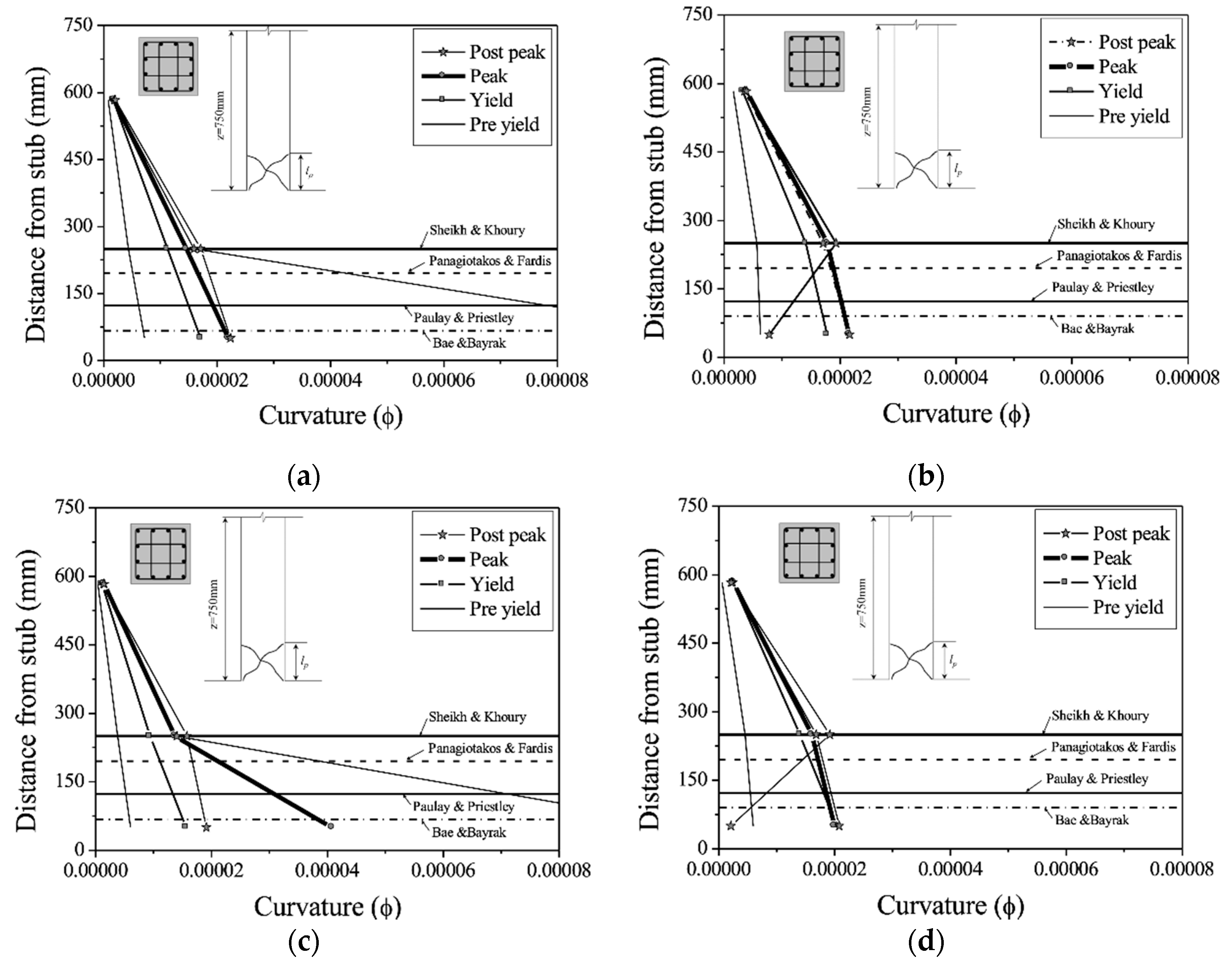
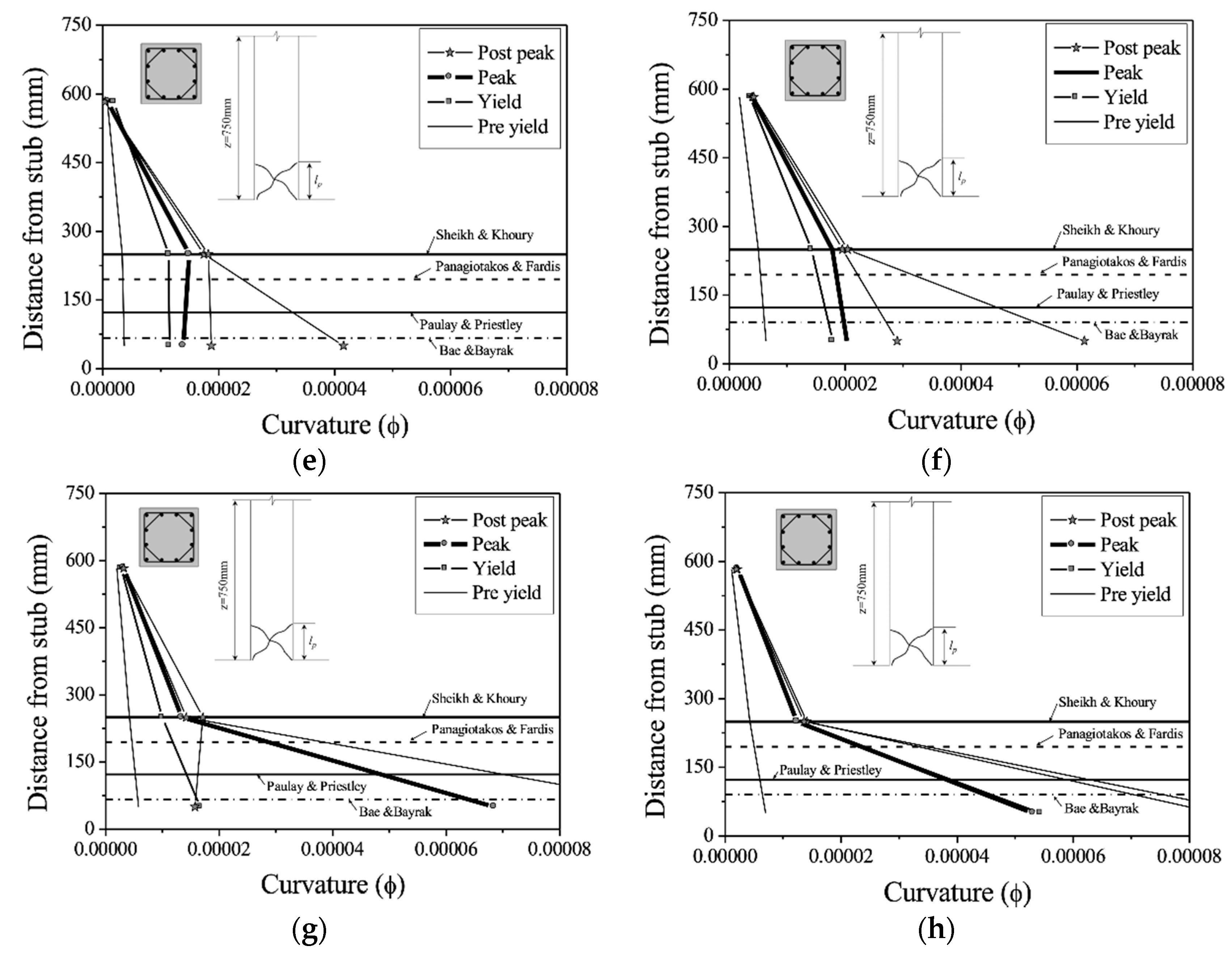
The plastic hinge length was calculated using the model proposed in past research, as shown in Table 3, to evaluate the lateral confinement performance of specimens [13,16,23,24]. Since the curvature of the plastic hinge zone serves as a basis for measuring the ductility of RC members, this study shows the plastic hinge zone-curvature relationship, as shown in Figure 10.
Regardless of the configuration of transverse reinforcement, the specimens developed a plastic hinge with a rapid increase in curvature after the yielding of longitudinal reinforcement at 250 mm (width) away from the 0 on the horizontal axis (stub end). This is similar to the plastic hinge proposed by Sheikh and Khoury in 1993 [16]. H-series specimens with an axial force ratio of 20% saw an increase in curvature after the peak load, but those with an axial force ratio of 30% did not show any increase in curvature after the peak load. As such, H-series transverse reinforcement with ties were unable to provide effective lateral confinement under high axial force, and eventually experienced failure. On the other hand, the curvature of S-series specimens increased after peak load in the plastic hinge zone (0–250 mm), and specimens having transverse reinforcement with a yield strength of 1050 MPa had a large curvature even when the axial force ratio was 30%. Spiral transverse reinforcement with alternating squares and octagons provided more effective lateral confinement to the core concrete and longitudinal reinforcement within the plastic hinge zone even with 55% less transverse reinforcement; the use of high-strength transverse reinforcement in RC members under high axial force is expected to significantly improve lateral confinement performance.

4.4. Energy Dissipation

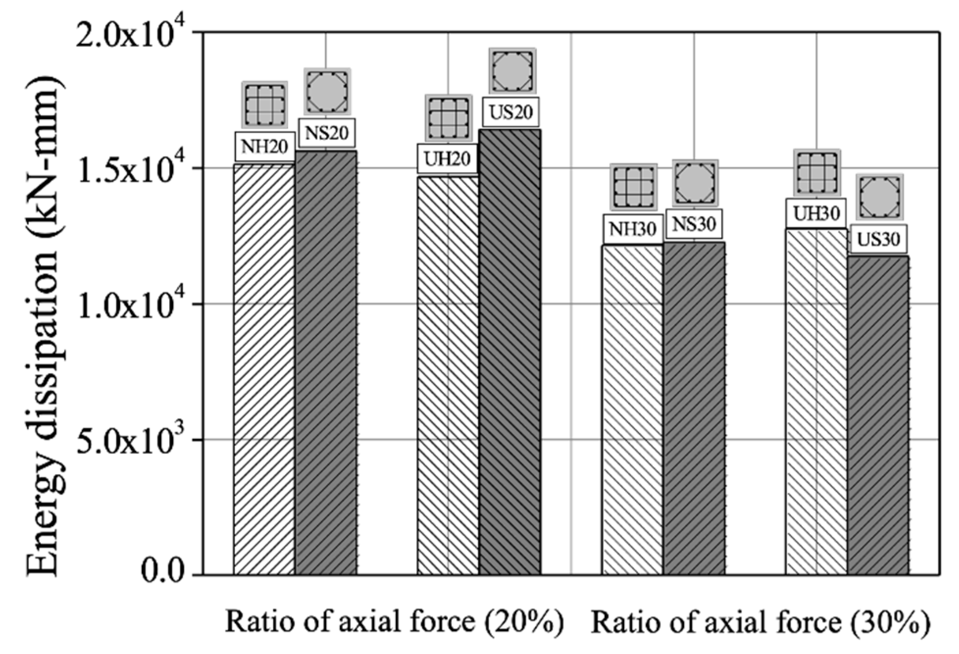
Figure 11 shows the accumulated energy dissipation capacity of specimens. The energy dissipation capacity of specimens was calculated by accumulating the total area of the lateral load-displacement curve, following the method of Elmenshawi and Brown, 2010 [25]. Compared to the H-series, the S-series except US30 had a higher energy dissipation capacity by 1.01 to 1.12 times. Regardless of configuration and yield strength of transverse reinforcement, the ductility of specimens dropped with increasing axial force ratio (Figure 9), resulting in a decrease in energy dissipation capacity. Compared to the H-series, the S-series, having an axial force ratio of 20%, showed a more distinct trend in energy dissipation capacity with increasing yield strength of transverse reinforcement.

5. Conclusions

In this study, an experiment was performed on RC columns with variables affecting the lateral confinement of the RC member, such as the configuration of the transverse reinforcement, the yield strength of the transverse reinforcement, and the axial force ratio. The main variables were configuration of transverse reinforcement, yield strength of transverse reinforcement, and axial force ratio. The conclusions obtained from the experiments are as follows.
  • S-series specimens with alternating square and octagonal shapes showed maximum strength values similar to those of the H-series confined with square ties, even with a 55% decrease in transverse reinforcement amount. The spiral S-series transverse reinforcement effectively prevented buckling of longitudinal reinforcement and provided lateral confinement to the core concrete, thereby allowing specimens to exhibit ductile behavior.
  • Compared to the H-series, the S-series had a 1.1 to 2.2 times higher ductility factor. The S-series showed superior ductile performance even under high axial force ratio when the yield strength of transverse reinforcement was increased. The curvature in the plastic hinge zone was high for the S-series, comprised of high-strength transverse reinforcement. The use of high-strength spiral transverse reinforcement in RC members subject to high axial force is expected to significantly improve the lateral confinement, and improve the ductility.
  • Compared to the H-series, the S-series specimens except US30 showed similar or higher energy dissipation capacity, and were thus verified as effective against seismic loads.

Author Contributions

Conceptualization, M.-J.K.; methodology, M.-J.K.; validation, M.-J.K.; formal analysis, M.-J.K.; investigation, M.-J.K. and B.-S.L.; resources, D.-H.K. and S.-P.H.; data curation, M.-J.K. and B.-S.L.; writing—original draft preparation, M.-J.K. and D.-H.K.; writing—review and editing, K.-H.K. and S.-P.H.; visualization, M.-J.K. and D.-H.K.; supervision, K.-H.K.; project administration, M.-J.K.; funding acquisition, K.-H.K. All authors have read and agreed to the published version of the manuscript.

Funding

This research received no external funding.

Institutional Review Board Statement

Not applicable.

Informed Consent Statement

Not applicable.

Data Availability Statement

Not applicable.

Acknowledgments

This work was supported by the Priority Research Center’s Program through the National Research Foundation of Korea (NRF) funded by the Ministry of Education (2019R1A6A1A03032988). This research was supported by Basic Science Research Program through the National Research Foundation of Korea (NRF) funded by the Ministry of Education (2018R1A2B3001656). This research was supported by a grant (21CTAP-C153039-03) from Technology Advancement Research Program (TARP) funded by the Ministry of Land, Infrastructure, and Transport of the Korean government.

Conflicts of Interest

The authors declare no conflict of interest.

Notations

  • a = Depth of equivalent rectangular stress block
  • A l = Area of longitudinal reinforcement
  • A e = Effective area of cross-section
  • A g = Gross area of concrete section
  • A s = Area of tension longitudinal reinforcement
  • A s i = Cross-sectional of longitudinal reinforcement in each layer
  • A t = Area of transverse reinforcement
  • b = Width of compression face of member
  • d = Distance from extreme compression fiber to centroid of longitudinal tension reinforcement
  • d b = Diameter of longitudinal reinforcement
  • d i = Distance from extreme compression fiber to centroid of longitudinal compression reinforcement
  • f c = Compressive strength of concrete (MPa)
  • f y l = Yield strength of longitudinal reinforcement (MPa)
  • f y t = Yield strength of transverse reinforcement (MPa)
  • h = Overall height of member
  • i = Layer of longitudinal reinforcement
  • P = Applied axial force
  • P o = Nominal axial load capacity as per ACI318-19
  • s = Spacing of transverse reinforcement (mm)
  • s l = Perimeter of transverse reinforcement per 1 pitch (mm)
  • z = Distance from critical section to point of contraflexure
  • ε s c = longitudinal strain of compression zone
  • ε s t = Longitudinal strain of tension zone
  • ρ t = Transverse reinforcement ratio ( A t s l / A e s )
  • ρ t f y t = Amount of transverse reinforcement
  • ϕ = Curvature of specimen

References

  1. Mattock, A.H. Redistribution of design bending moments in reinforced concrete continuous beams. Proc. Inst. Civ. Eng. 1959, 13, 35–46. [Google Scholar] [CrossRef]
  2. Carmo, R.; Lopes, S.M. Ductility and linear analysis with moment redistribution in reinforced high-strength concrete beams. Can. J. Civ. Eng. 2005, 32, 194–203. [Google Scholar] [CrossRef]
  3. Eom, T.S. Redistribution of Negative Moments in Beams Subjected to Lateral Load. J. Korea Concr. Inst. 2011, 23, 731–740. (In Korean) [Google Scholar] [CrossRef]
  4. SSheikh, A.; Yeh, C.C. Tied concrete columns under axial load and flexure. ASCE J. Struct. Eng. 1990, 116, 2780–2800. [Google Scholar] [CrossRef]
  5. Wang, Q.; Zhoo, G.; Lin, L. Effect of axial load ratio and stirrups volume ratio on ductility of high-strength concrete columns. Spec. Publ. 1994, 149, 433–448. [Google Scholar]
  6. Park, J.W.; Woo, J.H.; Kim, B.I.; Lee, J.Y. Plastic Hinge Length of Reinforced Concrete Columns with Low Height-to-Width Ratio. J. Korea Concr. Inst. 2010, 22, 675–684. (In Korean) [Google Scholar] [CrossRef] [Green Version]
  7. Lee, J.M.; Lee, Y.J.; Jung, Y.J.; Park, J.H.; Lee, B.S.; Kim, K.H. Ductile capacity of reinforced concrete columns with electric arc furnace oxidizing slag aggregate. Constr. Build. Mater. 2018, 162, 781–793. [Google Scholar] [CrossRef]
  8. Watson, S.; Park, R. Simulated seismic load tests on reinforced concrete columns. ASCE J. Struct. Eng. 1994, 120, 1825–1849. [Google Scholar] [CrossRef]
  9. Sakai, K.; Sheikh, S.A. What do we know about confinement in reinforced concrete columns. ACI Struct. J. 1989, 86, 192–207. [Google Scholar]
  10. Paultre, P.; Légeron, F. Confinement reinforcement design for reinforced concrete columns. ASCE J. Struct. Eng. 2008, 134, 738–749. [Google Scholar] [CrossRef]
  11. Kim, Y.S.; Kim, S.W.; Lee, J.Y.; Lee, J.M.; Kim, H.G.; Kim, K.H. Prediction of stress–strain behavior of spirally confined concrete considering lateral expansion. Constr. Build. Mater. 2016, 102, 743–761. [Google Scholar] [CrossRef]
  12. Wang, P.; Shi, Q.; Wang, F.; Wang, Q. Seismic behaviour of concrete columns with high-strength stirrups. Earthq. Struct. 2020, 18, 15–25. [Google Scholar]
  13. Paulay, T.; Priestley, M.J.N. Seismic Design of Reinforced Concrete and Masonry Buildings; John Wiley and Sons: New York, NY, USA, 1992. [Google Scholar]
  14. Abdel-Halim, M.A.; Abu-Lebdeh, T.M. Analytical study for concrete confinement in tied columns. ASCE J. Struct. Eng. 1989, 115, 2810–2828. [Google Scholar] [CrossRef]
  15. Sheikh, S.A.; Yeh, C.C. Flexural behavior of confined concrete columns. ACI Struct. J. 1986, 83, 389–404. [Google Scholar]
  16. Sheikh, S.A.; Khoury, S.S. Confined concrete columns with stubs. ACI Struct. J. 1993, 90, 414. [Google Scholar]
  17. Mo, Y.L.; Wang, S.J. Seismic behavior of RC columns with various tie configurations. ASCE J. Struct. Eng. 2000, 126, 1122–1130. [Google Scholar] [CrossRef]
  18. Lukkunaprasit, P.; Thepmangkorn, J. Load history effect on cyclic behavior of reinforced concrete tied columns. ASCE J. Struct. Eng. 2004, 130, 1629–1633. [Google Scholar] [CrossRef]
  19. Samra, R.M.; Deeb, N.A.; Madi, U.R. Transverse steel content in spiral concrete columns subject to eccentric loading. ACI Struct. J. 1996, 93, 412–419. [Google Scholar]
  20. Kim, M.J.; Kim, D.H.; Kim, D.H.; Kim, S.W.; Lee, J.Y.; Kim, K.H. Evaluation of flexural performance of RC columns according to configuration of transverse reinforcement. J. Archit. Inst. Korea Struct. Constr. 2012, 28, 3–10. (In Korean) [Google Scholar]
  21. American Concrete Institute. ACI Committee 318 Building Code Requirements for Structural Concrete (ACI 318M-19) and Commentary; American Concrete Institute: Farmington Hills, MI, USA, 2019. [Google Scholar]
  22. Park, R.; Paulay, T. Reinforced Concrete Structures; John Wiley and Sons: New York, NY, USA, 1975. [Google Scholar]
  23. Panagiotakos, T.B.; Fardis, M.N. Deformations of reinforced concrete members at yielding and ultimate. ACI Struct. J. 2001, 98, 135–148. [Google Scholar]
  24. Bae, S.; Bayrak, O. Plastic hinge length of reinforced concrete columns. ACI Struct. J. 2008, 105, 290–300. [Google Scholar]
  25. Elmenshawi, A.; Brown, T. Hysteretic energy and damping capacity of flexural elements constructed with different concrete strengths. Eng. Struct. 2010, 32, 297–305. [Google Scholar] [CrossRef]
Figure 1. Details of specimens: (a) H-series; (b) S-series (1 mm = 0.0394 in.).
Applsci 11 06696 g001aApplsci 11 06696 g001b
Figure 2. Name of specimen.
Applsci 11 06696 g002
Figure 3. Stress–strain relationship of reinforcement.
Applsci 11 06696 g003
Figure 4. Test setup of specimen: (a) View of test setup; (b) Loading history; (c) Measurement of displacement.
Applsci 11 06696 g004aApplsci 11 06696 g004b
Figure 5. Relationship of lateral load-drift angle of specimens: (a) NH20; (b) NH30; (c) UH20; (d) UH30; (e) NS20; (f) NS30; (g) US20; (h) US30.
Applsci 11 06696 g005aApplsci 11 06696 g005b
Figure 6. Failure mode of specimens: (a) NH20; (b) NH30; (c) UH20; (d) UH30; (e) NS20; (f) NS30; (g) US20; (h) US30.
Applsci 11 06696 g006aApplsci 11 06696 g006b
Figure 7. Strain distributions of longitudinal reinforcement: (a) NH20; (b) NH30; (c) UH20; (d) UH30; (e) NS20; (f) NS30; (g) US20; (h) US30.
Applsci 11 06696 g007aApplsci 11 06696 g007b
Figure 8. Strain distributions of transverse reinforcement: (a) NH20; (b) NH30; (c) UH20; (d) UH30; (e) NS20; (f) NS30; (g) US20; (h) US30.
Applsci 11 06696 g008aApplsci 11 06696 g008b
Figure 9. Ductility factors of specimen.
Applsci 11 06696 g009
Figure 10. Relationship of plastic hinge-curvature of specimens: (a) NH20; (b) NH30; (c) UH20; (d) UH30; (e) NS20; (f) NS30; (g) US20; (h) US30.
Applsci 11 06696 g010aApplsci 11 06696 g010b
Figure 11. Calculate of energy dissipation (kN-mm).
Applsci 11 06696 g011
Table 1. Properties of specimens (1 MPa = 145 psi, 1 mm = 0.0394 in.).
Specimens f c   ( MPa ) Longitudinal ReinforcementTransverse Reinforcement A e
(mm2)
Axial Load
(kN)
A l
(mm2)
f y l
(MPa)
A t
(mm2)
S
(mm)
f y t
(MPa)
ρ t
(%)
ρ t f y t
(MPa)
Hoop
type
NH203671.3
(12-D10)
300
( ε y = 0.0017)
28
(D6.1)
63.3
( S l = 1680 mm)
4531.205.4362,500450
NH304535.43675
UH20105012.6450
UH30105012.6675
Spiral
type
NS2045.3
( S l
= 754 mm)
4535.4338,680450
NS304535.43675
US20105012.6450
US30105012.6675
A l = Area of longitudinal reinforcement; A t = Area of transverse reinforcement; A e = Effective area of cross-section; f c = Compressive strength of concrete (MPa); f y l = Yield strength of longitudinal reinforcement (MPa); f y t = Yield strength of transverse reinforcement (MPa); s = Spacing of transverse reinforcement (mm); s l = Perimeter of transverse reinforcement per 1 pitch (mm); ρ t = Transverse reinforcement ratio ( A t s l / A e s ); ρ t f y t = Amount of transverse reinforcement.
Table 2. Test results (1 kN = 4.45 kips, 1 MPa = 145 psi, 1 mm = 0.0394 in).
Specimens V y . e x p V u . e x p M y . e x p M u . e x p ϕ u ϕ y M u . a n a   ( kN · m ) M u . e x p M u . a n a
V y . e x p   ( kN ) Drift   angle   ( Δ y ) V u . e x p   ( kN ) Drift Angle
( Δ u )
M y . e x p   ( kN · m ) ϕ y M u . e x p   ( kN · m ) ϕ u
NH20810.5%
(7.6 mm)
1011.3%
(18.8 mm)
617.2 × 10−6762.2 × 10−53.1621.23
NH301020.6%
(8.6 mm)
1171.0%
(15.0 mm)
776.3 × 10−6882.2 × 10−53.4771.14
UH20900.5%
(7.6 mm)
1051.3%
(18.8 mm)
686.0 × 10−6794.1 × 10−56.8621.27
UH301020.5%
(7.8 mm)
1211.1%
(17.0 mm)
775.9 × 10−6912.1 × 10−53.4771.18
NS20840.5%
(7.5 mm)
991.2%
(18.5 mm)
633.1 × 10−6741.4 × 10−53.8621.19
NS301020.5%
(8.6 mm)
1171.1%
(15.0 mm)
776.4 × 10−6882.0 × 10−53.2771.14
US20820.5%
(7.4 mm)
971.3%
(19.0 mm)
625.1 × 10−6736.9 × 10−511.8621.18
US30980.45%
(6.5 mm)
1160.8%
(11.9 mm)
747.0 × 10−6875.3 × 10−57.6771.13
V y . e x p : Yield strength of specimen (kN); Δ y : Displacement of specimen at yield (mm); V u : Peak strength of specimen (kN); Δ u . e x p : Displacement of specimen at Peak (mm); M y . e x p : Yield moment of specimen (kN·m); M u . e x p : Peak moment of specimen (kN·m); M u . a n a : Peak moment of ACI318-19 (kN·m); ϕ y : Curvature at yield moment; ϕ u : Curvature at peak moment.
Table 3. Previous studies of plastic hinge length for RC columns.
Researcher ReferencePlastic Hinge Length Model
Paulay and Priestley (1992) 0.08 z + 0.022 d b f y (for RC columns)
Sheikh and Khoury (1993) 1.0 h (for columns under high axial loads)
Panagiotakos and Fardis (2001) 0.18 z + 0.021 d b f y (for RC beams and columns)
Bae and Bayrak (2008) l p / h = [ 0.3 ( p / p 0 ) + 3 ( A s / A g ) 0.1 ] ( z / h ) + 0.25 0.25 (for columns)
A g : Gross area of concrete section; A s : Area of tension longitudinal reinforcement; d b : Diameter of longitudinal reinforcement; f y : Yield stress of longitudinal reinforcement; h : Overall height of member; P : Applied axial force; Po: Nominal axial load capacity as per ACI318-19; z: Distance from critical section to point of contraflexure.
Publisher’s Note: MDPI stays neutral with regard to jurisdictional claims in published maps and institutional affiliations.