1. Introduction
Generally, the charging station for electric vehicles (EV) has two types of electromagnetic interference (EMI). First, the pile is easily subjected to the surge shock from inductive or direct lightning strikes because it is installed outside. In addition, ground faults or cut-off inductive loads would cause EMI to the system. Both types of interference signals are characterized by high amplitude, short period, and wide spectrum; they occur in the form of pulse group [
1,
2,
3]. The signal, which could induce transient high voltage and large current on the wire of the charging station, has destructive effects on the devices, such as equipment misoperation and logic malfunction [
4,
5,
6,
7]. In particular, the surge shock signal of inductive or direct lightning causes permanent damage to the equipment; thus, it becomes unusable. The consequences become increasingly serious when an EV is charging. Therefore, conducting an electromagnetic compatibility (EMC) test on the piles is extremely indispensable. Among the numerous test approaches of EMC for the charging station, EFT test is one of the most effective methods; it simulates EMI signals in the form of rapid high-voltage transient pulse signals generated by high-voltage pulse source and tests the ability of anti-interference for the charging station [
8,
9].
In the EFT test, the interference signal waveform is analogous to the lightning current waveform with rapidly increasing edge based on double-exponential fitting in the time domain [
10,
11,
12]. Lightning has the characteristics of large current amplitude, high steepness, and tough impact overvoltage. In addition, the lightning discharging does not occur only once in space; it is an intermittent pulse development process called “stepped leader,” and the intermittent duration is approximately tens of microseconds. Thus, the lightning discharging process could be regarded as a group of several sharp pulses in an instant [
13,
14,
15]. Hydrogen thyratron was selected as the switch of the developed sources to realize pulse outputs to simulate pulse group with the time interval of several hundred microseconds because of the characteristics of lightning. The repetition rate of the thyratron cannot satisfy the requirements under the current technological condition. Thus, a trigger circuit with special topology, where the same four modules were connected to the load, should be adopted. Each module was triggered in the time sequence to obtain four continuous electromagnetic pulses with 100 μs step adjustable time interval and up to 35 kV amplitude.
2. Pulse Source Analysis
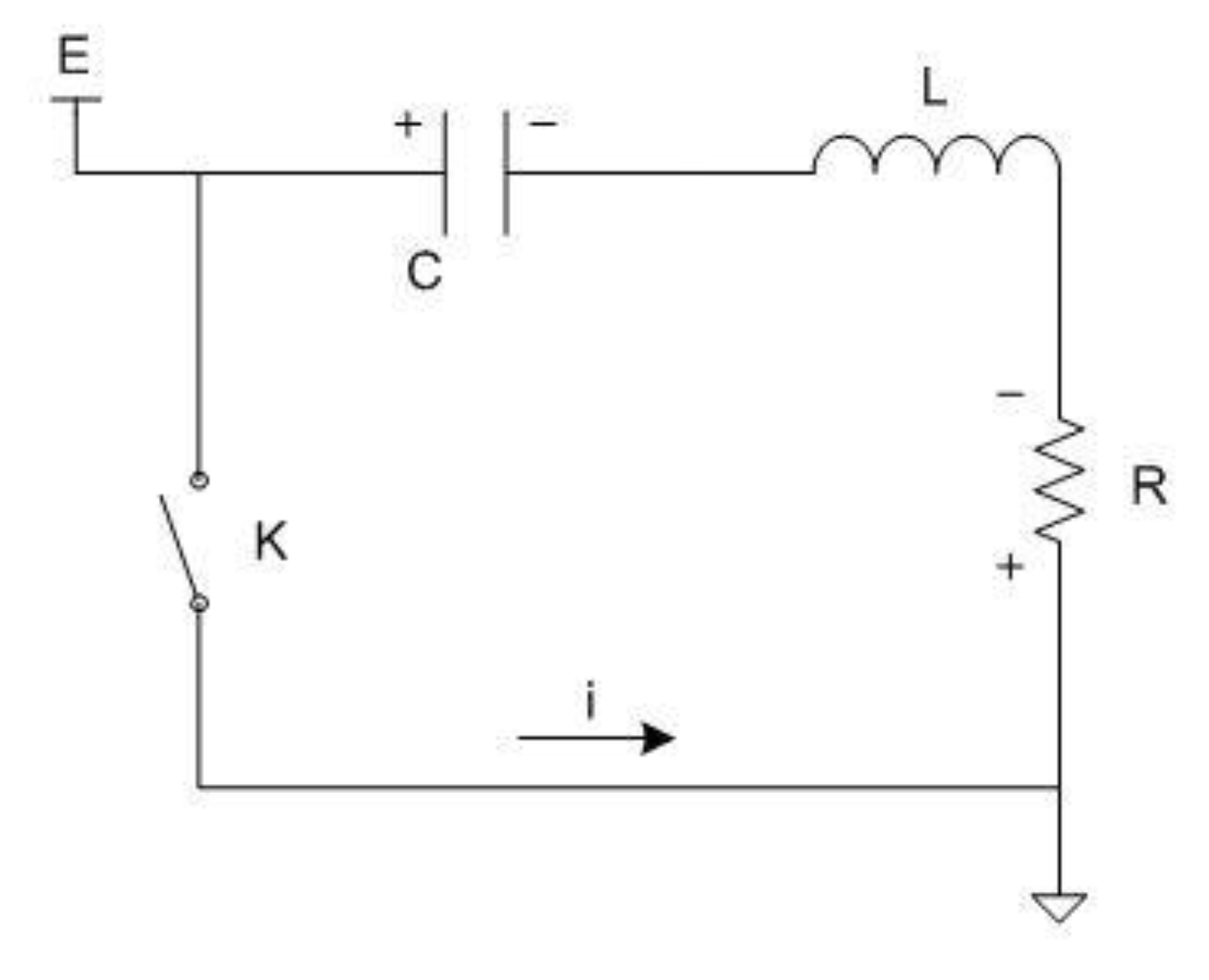
The expected output pulse waveform of the source accorded with the double-exponential waveform and the single generating circuit, which could be equivalent to the RCL circuit, as illustrated in
Figure 1. In the figure, K is the switch, C is the charging capacitor, L is the equivalent distributed inductance, R is the equivalent resistant, and E is the high-voltage charging source. Charged by the source to voltage of E, C supplied the load after K was triggered. Then, a double-exponential waveform electromagnetic pulse could be obtained under a certain physical condition.
K is an idle switch, and turned on at
t = 0; thus, the equivalent equation can be as follows:
Differentiating Equation (1), a second differential equation can be obtained as follows:
The square roots of Equation (2) are obtained as follows:
Suppose that the voltage on
C is
and the initial condition is
, the discharge process of the circuit could be regarded as overdamped when
. Then, the current equation is as follows:
Hence, the output voltage pulse of the load
R is obtained as follows:
In addition,
where
α is commonly far more than
β. The rise and fall time (
and
) of the pulse could be obtained using Equation (7) under the case of
, as follows:
The simulated waveform of pulse output is demonstrated in
Figure 2, where
C = 0.1 μF,
L = 10 μH,
R = 300 Ω, and
E = 50 kV.
3. Method to Obtain EFT
The repetition rate electromagnetic pulse with short-time interval, which is usually tens to hundreds of microseconds, should be acquired to simulate the lightning discharging process. The pulse interval is extremely small, and the frequency could be converted to approximately 10 kHz. Although the working frequency of hydrogen thyratron has been developed currently, it is still far from reaching the demands. Hence, a special topological circuit should be utilized.
Figure 1 illustrates a type of double-exponential waveform generating circuit, where the function of pulse output waveform could approximately be equal to Equation (8) on a charge–discharge period
T, which was approximately 0.1 s to tens of seconds.
In the former equation,
D is the width of pulse output, and
Therefore, provided that the same circuit was added to generate the same pulse in the interval of the end of the first discharge and the beginning of the second discharge by the former, the number of the pulse output could be doubled. Theoretically, several pulses could be added in the interval to generate a pulse sequence, which depends on the recovery time of hydrogen thyratron. A linear superposition relationship is found between the number of pulse strings on the load and the double-exponential wave generating circuit.
High-repetition rate electromagnetic pulse could be obtained on the load by utilizing the linear superposition theory, which was analyzed in detail in combination with
Figure 3, where three generating circuits were considered.
The working principle illustrates that the pulse sources
A,
B, and
C independently generated electromagnetic pulse to the load in separate time with the same interval. Thus, a continuous pulse string with certain frequency could be obtained on the load. The period of pulse string was marked
T. The outputs of sources
A,
B, and
C could be deduced as Equation (10), according to Equation (8):
Supposed that the independent sources were triggered in timing and the time interval between two pulses was Δ
t, the output waveform on the load could be indicated in Equation (11) in one cycle, as follows:
Under the condition of Δt ≥ D, high-repetition rate pulse strings without overlaps in the waveforms would be acquired by the linear superposition method because the sources are independent. Therefore, the waveform with N pulses in one cycle could also be obtained through controlling and triggering the switches of N independent sources to turn on with equal time interval. The triggering action occurred every 3.5 periods of a single pulse of the pulse group considering the self-recovery time of thyratron and the delay of double-exponential waveform.
4. Electromagnetic Compatibility Protection of the System
4.1. Analysis for the Interference Model of Electromagnetic Pulse Conduction
Although the pulse-generating sources were operated independently, electromagnetic interference cannot be avoided due to the common load. The interference, which would exert a severe influence on the operation of the system without protection methods, could be divided by electromagnetic radiated interference and common-ground coupling interference [
16,
17]. The former was electromagnetic radiation, which was approximately antenna-generated in the connected line or the feedback line of the system and received by the other working sources of the system directly; it could be prevented by metal-shielding measures. The latter was a type of conduction interference generated by loop coupling composed of distribution parameters, such as distributed capacitance and inductance [
18,
19,
20]; it was difficult to prevent because connecting the sources and elements in the same network and ground was inevitable.
The formation of common-ground coupling interference could be simply illustrated using
Figure 4, where two pulse sources are connected to the same ground; the discharge loop of hydrogen thyratron is found on the right. The loop consisting of K1-
C4-R1-K1 was a typical electromagnetic pulse-generating circuit or pulse source 2, and
C4 was the charging capacitance. The topology of the circuit in the left of
Figure 4 was the same as that in the right. Thus, the load R1 could be supplied by two synchronous or asynchronous pulses generated by the two pulse sources through timing control. When the left pulse source discharged in the loop 1, a coupling circuit could be formed with the distributed capacitance
C3 with conducted interference occurring. The coupling circuit could be simplified in another topology demonstrated in
Figure 5, in which the electromagnetic pulse generating circuit acting as the interference pulse source was marked by pulse source directly. The disturbed part was indicated by the circuit diagram for the sake of clarity.
C1 and
C2 were the distributed capacitances in the c, d ending and d, e ending of hydrogen thyratron.
C3 was the coupling capacitance between a and b points, and L1 was the equivalent distributed inductance in the circuit. The equivalent circuit of anode–cathode and grid–ground of thyratron, which was not triggered to turn on, was not illustrated.
When switch K is turned on at
t = 0, the equation of loop 2 is as follows:
where
is the output voltage of the interference pulse source.
Supposed that the initial condition was as follows:
, the voltage in
d–
e points could be obtained as follows:
The typical simulated waveform is indicated in
Figure 6 under the condition of
.
The analysis of
Figure 6 indicates that the grid of thyratron of source 2 was disturbed by the couple loop composed of distributed capacitance when the pulse source was discharged. The waveform was superposed by the interference pulse illustrated in
Figure 3. The thyratron might be falsely triggered when the width and amplitude of the interference waveform was up to a certain threshold value.
4.2. Electromagnetic Pulse Conduction Interference Test
4.2.1. Grid Interference Measurement
In the system shown in
Figure 3, although several pulse sources were operated independently, they had a common ground, which was also one of the two endings of triggering signal for grid. The common-ground coupling interference could disturb the grid of thyratron in this system. The four-pulse sources were numbered 1–4, and the thyratrons were numbered correspondingly. The test was conducted in No. 1 and No. 3 thyratrons. The interference signal waveform of No. 1 thyratron under the condition of No. 1 source out of operation and No. 3 source in operation was measured and illustrated in
Figure 7, where the output of source 3 had a superposed effect on No. 1 grid to some extent.
The high voltage of pulse source 3 is 20 kV, and the signal is attenuated 10 times. The ordinate in
Figure 7 represents the voltage (V), 10 V per grid, which is reduced by 10 times, and its amplitude is about 400 V.
Figure 7 shows that the reference aptitude of grid was as high as that indicated in
Figure 6. The grid of thyristor was sensitive to the outside pulse. The common trigger voltage was approximately 900 V; thus it was spuriously triggered easily.
4.2.2. Output Interference Test
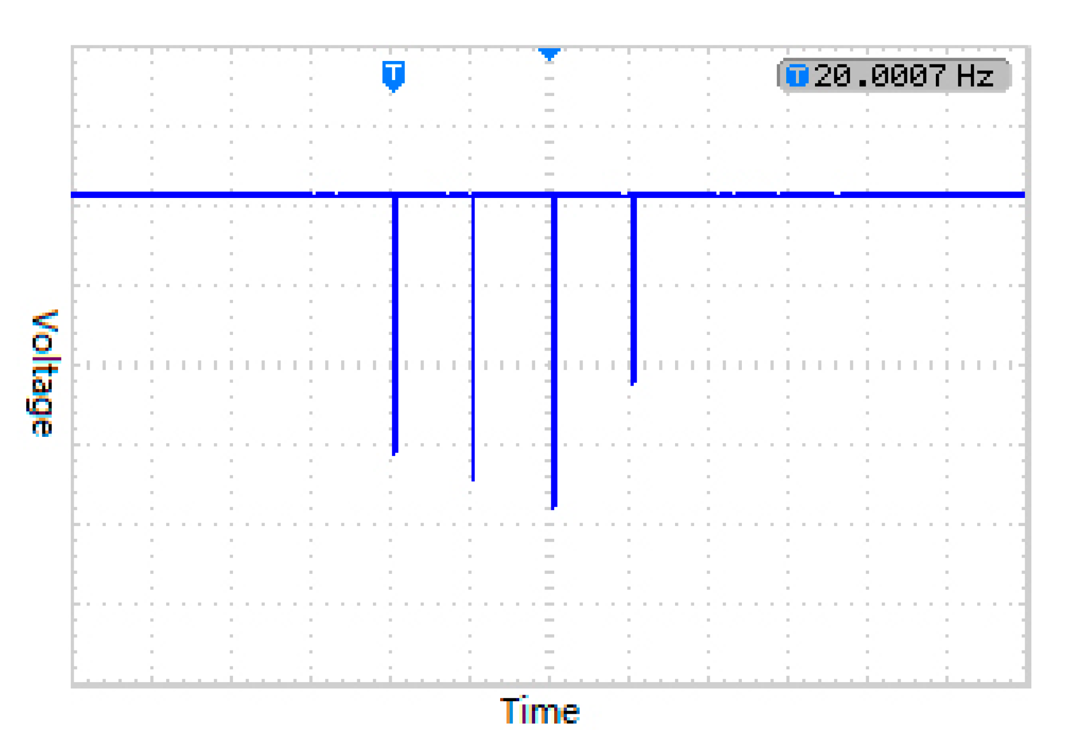
The test was conducted among three pulse sources, and the triggering order of thyristors was 1→2→3. The triggering pulse in the timing sequence for thyristor could be measured and sampled in RC matching circuit, and the sampling rate was 1:10,000. The on–off action of thyristor would be unstable as the output voltage of pulse sources raised gradually. The next thyristor in the timing sequence would be triggered falsely when the output voltage was up to 22 kV. When the interval is 200 μs, the triggering pulse is illustrated in
Figure 8, in which the waveform should have three pulses. However, only two pulses were found because the last output pulse marked by cyan arrow was superposed, as shown in
Figure 9.
In order to verify whether the error is caused by the distribution of thyristor parameters, an experiment is carried out to change the triggering sequence of thyristor, i.e., the original sequence was transformed to different sequences of 1→3→2 and 2→3→1. The result indicated that the last thyratron was still triggered falsely under the condition of the same voltage. Therefore, the conducted interference was improved.
4.3. Conduction Inference Suppression
The grid trigger pulse and the output pulse should be connected to the common ground based on the working characteristic of thyratron. This type of inference could be alleviated by the peak pulse circuit, which suppressed the interference through a rapid recovery diode (D1) and a discharge tube (F) illustrated in
Figure 10. The second gate trigger circuit of the hydrogen thyratron is shown in
Figure 10. Q1 is the modulation switch, and the ratio of the booster transformer is 1:3. When Q1 is closed, the stored energy of the transformer passes through the loop of T→R2→
C2→Q1→T to generate a transient high voltage trigger pulse, which enables the hydrogen thyratron to be switched on. The diode D1 is used to eliminate the pulse ring, the output trigger pulse amplitude is about 900 V, and the breakdown voltage of the discharge tube is 800 V. As shown in
Figure 7, the interference was mainly a negative polarity pulse. Therefore, the rapid recovery diode reversely paralleled with the grid input could positively affect the elimination of the inverse peak amplitude. The first positive peak could also be reduced. The discharge tube was connected in parallel to clamp the reference pulse.
The measuring result of the grid interference signal is indicated in
Figure 11 after the suppression circuit was added. The ordinate in
Figure 11 represents the voltage (V), 10 V per grid, which is reduced by 10 times, and its amplitude is about 80 V, so the second grid of thyristor cannot be triggered. Compared with the waveform without suppression circuit indicated in
Figure 7, the interference was effectively suppressed, thereby manifesting that the amplitude and effective width of the interference pulse were reduced evidently, and that the output amplitude of the source could be up to 33 kV without false triggering under the action of the third timing sequence.
5. Test Result
The multiple output electromagnetic pulse generator shown in
Figure 12 was debugged after it was assembled. The reliability and performance index of the simulator were also tested.
The experiment was conducted on the condition that the input voltage was 25 kv. Tektronix P6015A high-voltage probe and TDS1002B oscilloscope were adopted as the measuring tools. The testing items were composed of combined output waveforms of various electromagnetic pulse sequences, the intermittent duration adjustment for the pulse sequences, the amplitude of the pulsed electric field, and the increasing edge of the electric field. The results are presented in the following section.
The four-way electromagnetic pulse generators were numbered 1, 2, 3, and 4.
Figure 13 presents the test result of the group 1-2-3-4 (the difference of pulse amplitude was due to the normal output of the oscilloscope). The other groups can be set freely.
The interval time of the four-way pulse output could be adjusted with the step of 100 μs, the minimum interval was 100 μs, and the maximum was 1 ms. The waveform of 200 μs and 1 ms interval time are shown in
Figure 14 and
Figure 15, respectively.
6. Conclusions
The high repetition rate electromagnetic pulse was introduced. The formation mechanism of capacitive energy storage discharging electromagnetic pulse and the interference of pulse to the control system were analyzed. The test results showed that the pulse string with required interval and number could be obtained by the theory of linear superposition and that the interference improved. The peak pulse suppression circuit was introduced mainly to restrain the conduction interference. The results proved that the approach was effective.
Author Contributions
Conceptualization, X.P.; methodology, L.F. and Z.H.; software, X.Z.; writing—original draft preparation, L.F.; writing—review and editing, R.L. All authors have read and agreed to the published version of the manuscript.
Funding
This research was funded by Fund for the technical area of the Infrastructure Strengthening Programme, grant number 2019-JCJQ-JJ-380.
Institutional Review Board Statement
Not applicable.
Informed Consent Statement
Not applicable.
Data Availability Statement
Data are contained within this article; more detailed data can be obtained from the corresponding author.
Conflicts of Interest
The funders had no role in the design of the study; in the collection, analyses, or interpretation of data; in the writing of the manuscript, or in the decision to publish the results.
References
- Hamza, D.; Pahlevaninezhad, M.; Jain, P.K. Implementation of a novel digital active EMI technique in a DSP-based DC-DC digital controller used in electric vehicle (EV). IEEE Tran. Power Electron. 2013, 28, 3126–3137. [Google Scholar] [CrossRef]
- Rahman, S.A.; Zhang, N.; Jianguo, Z. Modeling and simulation of an energy management system for plug-in hybrid electric vehicles. In Proceedings of the 2008 Australasian Universities Power Engineering Conference, Sydney, Australia, 14–17 December 2008; pp. 1–6. [Google Scholar]
- Timperley, J.E.; Buchanan, D.W.; Vallejo, J.M. Electric generation condition assessment with electromagnetic interference analysis. IEEE Trans. Ind. Appl. 2018, 54, 1921–1929. [Google Scholar] [CrossRef]
- Howard, C.; Courtney, E. Mitigating electromagnetic and radio-frequency interference. Mil. Aerosp. Electron. 2018, 29, 18–25. [Google Scholar]
- Lennerz, C.; Pavaci, H.; Grebmer, C.; Semmler, V.; Bourier, F.; Haller, B. Electromagnetic interference in cardiac implantable electronic devices: Is the use of smartphones safe. J. Am. Coll. Cardiol. 2017, 69, 108–110. [Google Scholar] [CrossRef] [PubMed]
- CISPR; IEC. Part 1-1, Specification for Radio Disturbance and Immunity Measurement Apparatus and Methods—Part 1: Radio Disturbance and Immunity Measuring Apparatus; International Electrotechnical Commission: Geneva, Switzerland, 2015. [Google Scholar]
- Feng, D.; Lan, J. Analysis on conducted coupling of electrical fast transient burst in mines. J. Coal Sci. Eng. 2012, 18, 207–212. [Google Scholar] [CrossRef]
- Cerri, G.; Leo, R.D.; Primiani, V.M. Investigation of radiated susceptibility during EFT test. IEEE Tran. Electromag. Compat. 1997, 39, 298–303. [Google Scholar]
- Kanda, M. Standard antennas for electromagnetic interference measurements and method to calibrate them. IEEE Trans. Electromag. Compat. 1994, 36, 261–273. [Google Scholar] [CrossRef]
- Zhang, J.; Koo, J.; Moseley, R.; Herrin, S.; Li, X.; Pommerenke, D.; Beetner, D.G. Modeling injection of electrical fast transients into Power and IO Pins of ICs. IEEE Tran. Electromag. Compat. 2014, 56, 1576–1584. [Google Scholar] [CrossRef]
- Mei, H.; Yan, S.; Zhao, C.; Wang, L. Research on lightning current sensor coil based on lightning space magnetic field. IEEE Trans. Instrum. Meas. 2018, 67, 1922–1928. [Google Scholar] [CrossRef]
- Ala, G.; Favuzza, S.; Francomano, E.; Giglia, G.; Zizzo, G. On the distribution of lightning current among interconnected grounding systems in medium voltage grids. Energies 2018, 11, 771. [Google Scholar] [CrossRef] [Green Version]
- Rajicic, D.; Todorovski, M. Two-component current waveform for lightning simulation. IEEE Tran. Electromag. Compat. 2015, 57, 1062–1069. [Google Scholar] [CrossRef]
- Cerri, G.; De Leo, R.; Primiani, V.M. Electrical fast-transient test: Conducted and radiated disturbance determination by a complete source modeling. IEEE Tran. Electromag. Compat. 2015, 43, 37. [Google Scholar] [CrossRef]
- Lynn, B.H.; Kelman, G.; Ellrod, G. An evaluation of the efficacy of using observed lightning to improve convective lightning forecasts. Weather Forecast. 2015, 30, 405–423. [Google Scholar] [CrossRef]
- Sonoda, T.; Morii, H.; Sekioka, S. Observation of lightning overvoltage in a 500kV switching station. IEEE Tran. Power Deliv. 2017, 32, 1828–1834. [Google Scholar] [CrossRef]
- Long, M.; Becerra, M.; Rajeev, T. Modeling the attachment of lightning dart and dart-stepped leaders to grounded objects. IEEE Trans. Electromag. Compat. 2015, 59, 128–136. [Google Scholar] [CrossRef]
- Wang, Y.; Li, L.; Zou, J. Nanosecond-risetime high-voltage electrical fast transient/burst generator. Autom. Electr. Power Syst. 2006, 30, 96–100. [Google Scholar]
- Feng, D.; Xu, X.; Luo, J.; Lee, X.; Yao, Z.; Yu, C. A high-repetition-rate bounded-wave EMP simulator based on hydrogen thyratron and transmission line transformer. IEEE Trans. Plasma Sci. 2012, 40, 3499–3507. [Google Scholar] [CrossRef]
- Braun, C.G.; Erwin, D.A.; Gundersen, M.A. Fundamental processes affecting recovery in hydrogen thyratrons. Appl. Phys. Lett. 1987, 50, 1325–1327. [Google Scholar] [CrossRef]
| Publisher’s Note: MDPI stays neutral with regard to jurisdictional claims in published maps and institutional affiliations. |
© 2021 by the authors. Licensee MDPI, Basel, Switzerland. This article is an open access article distributed under the terms and conditions of the Creative Commons Attribution (CC BY) license (https://creativecommons.org/licenses/by/4.0/).


