Abstract
With the durable operation of high-speed railway tunnels in China, many tunnel defects successively appeared in the tunnel lining structure and gradually threatened the safe operation of the tunnels. In the limited maintenance time of high-speed railways, it is urgent to find out and maintain tunnel defects, especially internal defects. We propose an applied detection technology called the vehicle-mounted transient electromagnetic method (TEM). The detection technology aims to rapidly detect and locate the internal defects of the lining structure throughout the entire tunnel. Firstly, we investigate tunnel defects in detail and introduce the rapid detection method. Secondly, we analyze the principle and process of vehicle-mounted TEM. Thirdly, the rationality and applicability of vehicle-mounted TEM are verified by three different methods, including theoretical analysis, numerical simulation, and laboratory experiment. Finally, we compare the inversion results of experimental data under the two conditions. The results illustrate that tunnel surface defects are the external manifestations and characteristics of tunnel defects, while the forms of surface defects are directly related to internal defects. This detection method is suitable for the significant resistivity difference between tunnel defects and surrounding rocks, and its rationality is effectively validated. Furthermore, the apparent resistivity results reveal that there is a low resistivity region in front of the transmitter coil, and that the relative position can be preliminarily judged. The research results can provide a potential and significant application technology for the rapid detection of tunnel defects.
1. Introduction
Tunnel defects are a prominent problem in railway, highway, and underground engineering all over the world, especially the high-speed railway tunnels in China [1]. Due to the influence of various factors, such as geology, climate, design, and construction conditions, a variety of defects appear during the normal operation of tunnels, including water leakage, cavity, crack, and insufficient thickness of tunnel linings [2,3]. Therefore, tunnel defects are a worldwide hot problem, especially in the mountainous area of southwest China.
With the rapid construction of high-speed railway tunnels in China, situations of tunnel defects have been increasing rapidly in recent years, particularly in the last 2 to 3 years. For example, the completed line of the Guiyang section of the Shanghai–Kunming high-speed railway, with a design speed of 250 km/h, is 559.5 km in length [4]. There are 223 tunnels with a total length of 330.3 km, and the tunnel length accounts for 59% of the line length. Based on the investigation results of field survey and ground penetrating radar testing on 59 tunnels of this line, a total of 30,571 defects occurred in these tunnels in less than one year of operation, where the number of water leakages and cavities is as high as 1471 and 941, respectively. The same type of tunnel defects have already been found in many high-speed railway tunnels in operation. If not dealt with in time, it is only a matter of time before serious water leakages and even the collapse of tunnel linings occur, which will cause a great potential danger to the normal service of high-speed railway tunnels.
At present, four main problems are raised in the defect detection of high-speed railway tunnels. Firstly, serious defect problems have appeared in the high-speed railway tunnels. Then, more and more long-distance tunnels are being built and planned. Thirdly, high-speed railway tunnels will enter a peak period of maintenance in the next few years. Finally, the current manual detection method is unable to complete such a large detection in the short maintenance time of high-speed railway. According to the maintenance regulation of a high-speed railway tunnel [4,5], all maintenance work must be completed within a limited time. However, the present tunnel defect detection technology cannot meet all requirements of the rapid maintenance of a high-speed railway tunnel. Therefore, it is urgent to investigate an efficient and rapid detection method to accomplish such a large tunnel defect detection works within a limited maintenance time.
The transient electromagnetic method (TEM) is widely used in various fields, such as coal mine and tunnel construction exploration, deep-sea metal mineral exploration, and ground exploration [6,7]. Based on the identification performance of the low-resistivity body of TEM technology, the vehicle-borne TEM has been preliminarily proposed to rapidly detect tunnel defects behind tunnel linings [3], and the adaptability of this rapid detection method was also investigated [8,9]. Qian et al. [3] adopted the numerical simulation method to investigate the variation rule of the transient electromagnetic response curve of a low-resistivity water-bearing body at the condition of short-distance and whole-space, and revealed the transient electromagnetic digital characteristic parameters that can reflect the regular physical parameters of a low-resistivity water-bearing body. Liang et al. [8] used the combination of a least square support vector machine and particle swarm optimization algorithm to study the three-dimensional fast inversion of a short-distance low-resistivity water-bearing body, and realized the prediction of physical parameters of a low-resistivity water-bearing body. Li [9] investigated the whole-space electromagnetic response characteristics under different coil sizes by means of numerical simulation, proposed the most appropriate coil parameters for short-distance detection, and revealed the advantages and limitations of a small-dimension coil. Based on the existing literature review, the application of vehicle-mounted TEM illustrates a new characteristic, including the whole-space in the detection surroundings, small-dimension in the transmitter coil, and short-distance in the detection target. However, this rapid detection method has not been thoroughly investigated, and the current verification methods are mainly focused on numerical simulation and theoretical inversion. Thus, the suitability and feasibility of this rapid detection method need to be profoundly investigated through different methods.
To meet the technical requirements for the rapid detection of high-speed railway tunnels within a limited maintenance time, an applied detection technology called the vehicle-mounted transient electromagnetic method is proposed. Aimed at the rapid detection and location of the internal defects of the lining structure throughout the entire tunnel, the detection principle and process of vehicle-mounted TEM are deeply analyzed through the investigation of internal defects behind tunnel linings. Meanwhile, the rationality and applicability of vehicle-mounted TEM are verified by three different methods, including theoretical analysis, numerical simulation, and laboratory experiment. Finally, the inversion results of experimental data under the two conditions are comprehensively compared. The research results will provide a potential method for the rapid detection of tunnel defects.
2. Proposal of Vehicle-Mounted Transient Electromagnetic Method
2.1. Investigation of Operational Tunnel Defects
Tunnel structural defects are usually manifested on the lining surface, such as lining cracking, water leakage, concrete peeling, and convergence deformation [1,3,10,11,12]. The occurrence of these defects is usually a superficial characteristic, but it is closely related to the internal conditions of surrounding rocks. These internal conditions mainly include insufficient lining thickness, voids, water behind linings, etc., which are also known as tunnel internal defects. Therefore, the tunnel surface defects in most cases are directly related to tunnel internal defects. Essentially, tunnel internal defects are the origin of many tunnel surface defects to the same extent.
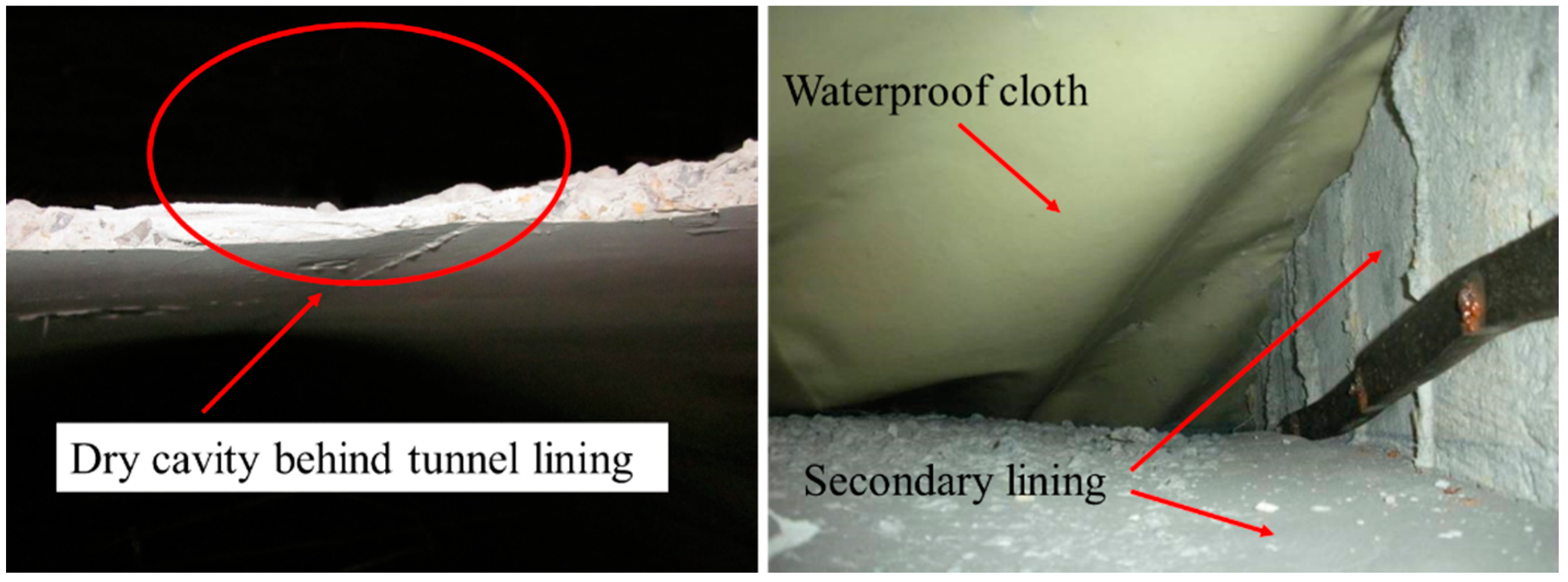
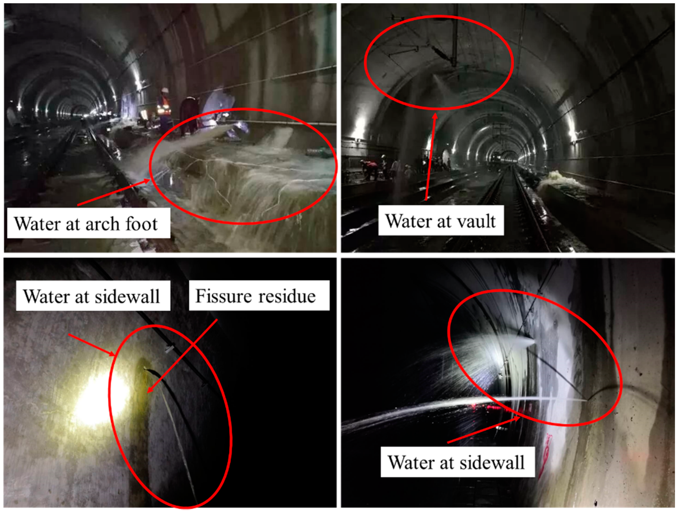
According to the investigation on the tunnel defects of high-speed railway tunnels in the mountainous area of southwest China, the lining thickness of many operational tunnels is insufficient, which further leads to the obvious dry cavity behind the lining, as shown in Figure 1. When the dry cavity is filled with water under the influence of continuous rainfall, the serious water-spraying phenomenon appears in a different position of the tunnel lining surface, such as the arch foot, vault, and sidewall, as shown in Figure 2. The above phenomenon shows that large amounts of hidden and undiscovered water exist behind the tunnel lining, and will seriously affect the normal operation of the tunnel structure.
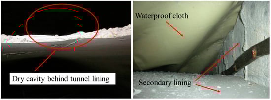
Figure 1.
Cavity phenomenon behind tunnel lining.

Figure 2.
Water leakage in different position of tunnel structure.
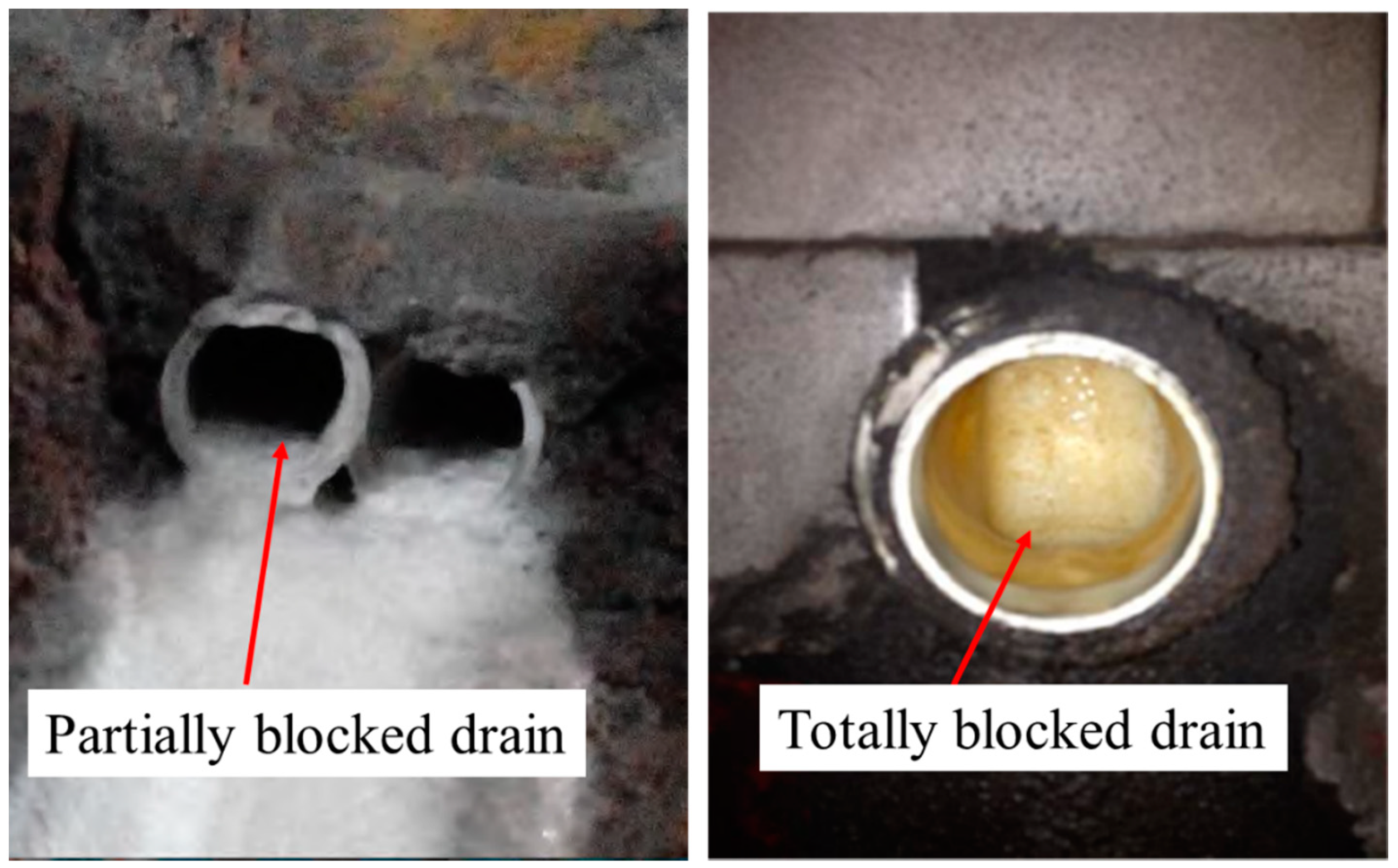
In general, this outflow of water contains a large amount of fissure residue, as shown in Figure 2. The accumulation of fissure residue blocks the tunnel drainage system, and the original water body is undischarged smoothly. Meanwhile, many limestone tunnels are rich in calcium carbonate in southwest China, and the drainage outlets of such tunnels are prone to crystallization. Under the dual action of the crystallization of calcium carbonate and accumulation of fissure residue, the drainage system of tunnel lining will be partially or completely blocked during the long-term operation of tunnels, as shown in Figure 3. Due to the limitation of the drainage function, the normally discharged water will gradually accumulate behind the tunnel lining. This phenomenon has a long time-dependent effect. The hidden and undiscovered water gathered behind the tunnel lining cannot be found without involving the normal operation and structural safety of the tunnel lining.
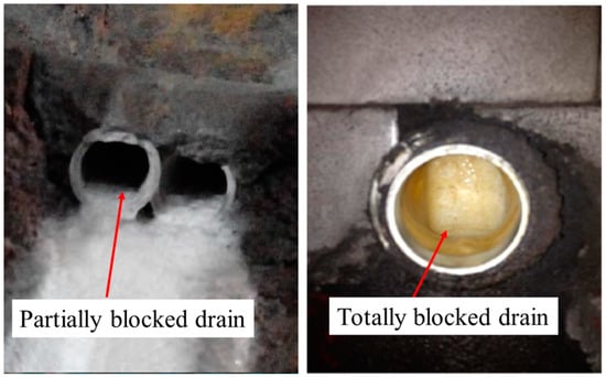
Figure 3.
Blocking phenomenon of tunnel drainage system.
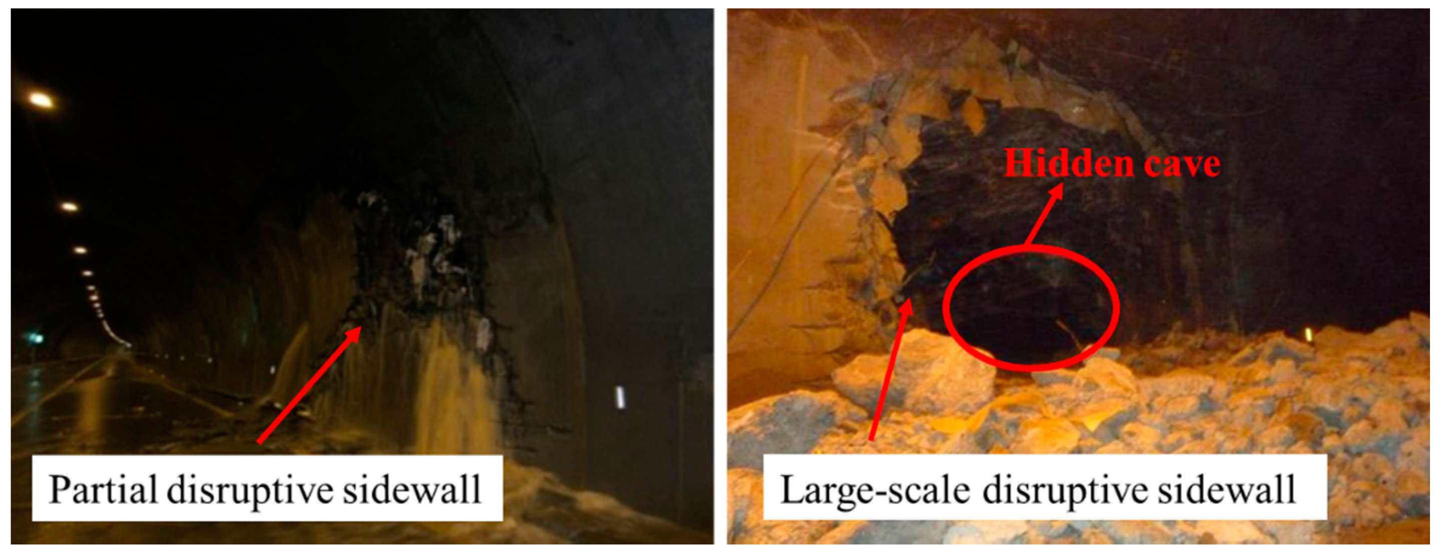
With further damage to the drainage system of the tunnel lining, a large amount of water accumulates behind the tunnel lining. Once the accumulated water reaches a certain level, different degrees of water leakage will occur to the surface of the tunnel lining, as shown in Figure 2. This hidden and undiscovered water behind the tunnel lining is applied to the tunnel lining structure in the form of water pressure. As for non-drainage tunnels, the stress state of the lining structure is usually changed, and the bearing capacity of the tunnel lining is seriously reduced. When the maximum bearing capacity of the non-drainage tunnel is not enough to support the hidden and undiscovered water behind the tunnel lining, the lining structure will suffer local or overall instability, which is manifested as the partial or large-scale disruption of the secondary lining, as shown in Figure 4. This hidden and undiscovered water behind the tunnel lining can only be discovered and revealed when the serious phenomena of water leakage and lining disruption are found. Therefore, it is an urgent problem for tunnel maintenance engineers to detect and find the hidden and undiscovered water behind the tunnel lining.

Figure 4.
Disruption phenomenon of secondary lining.
2.2. Detection Method of Tunnel Defects
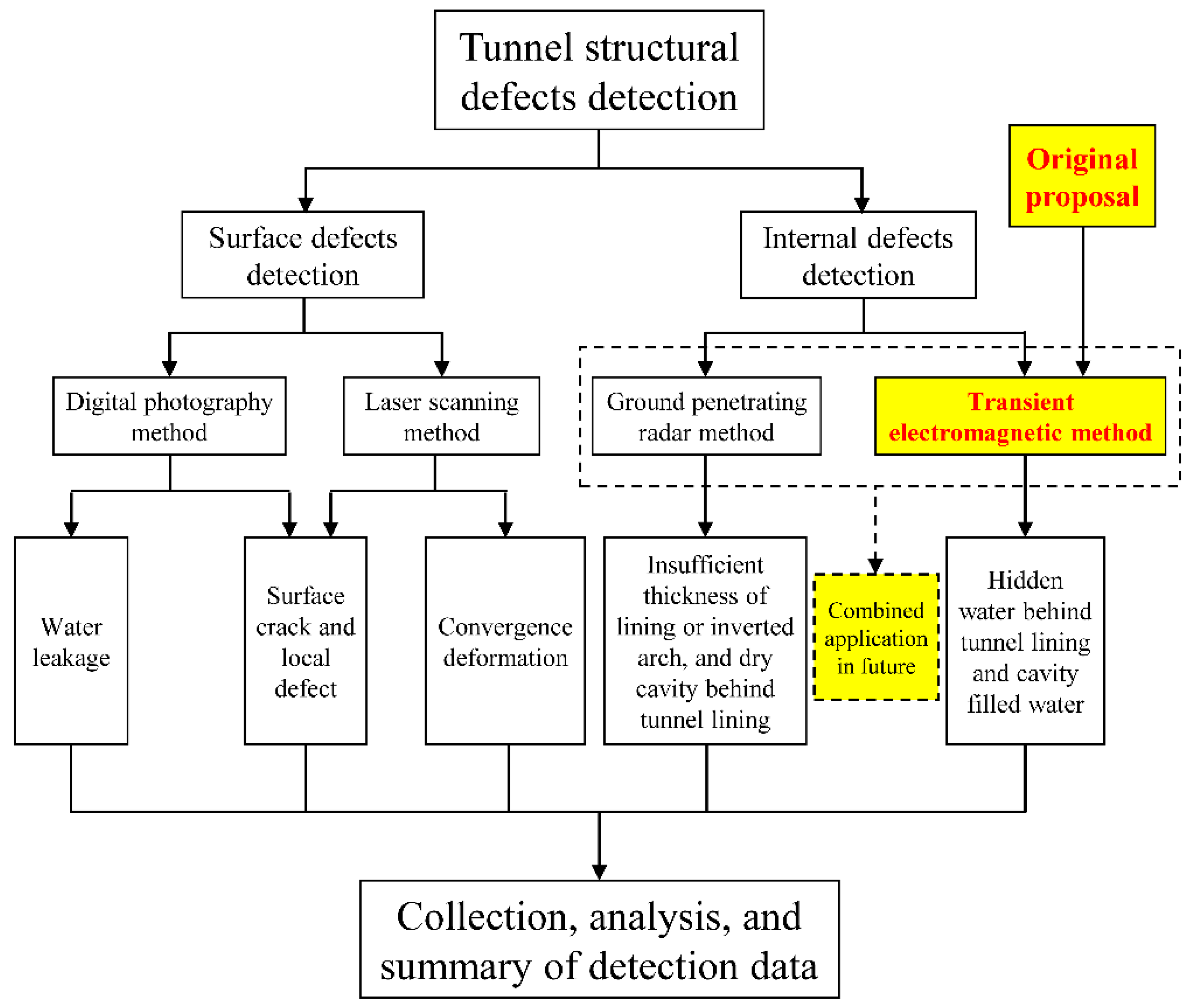
In the detection of tunnel defects, advanced technologies have been applied, including the digital photography method, laser scanning method, and ground penetrating radar method, as illustrated in Figure 5. The digital photography method can distinguish the water leakage at the surface of tunnel linings, but the amount of water leakage cannot be distinguished [10]. The laser scanning method can measure the convergence deformation [11]. The surface crack and local defect of surface defects can be identified by both the digital photography method and the laser scanning method [11,12]. The above detection methods applied in tunnel surface defects can reach 50 km/h, and some can even exceed 80 km/h under the condition of low accuracy. As for internal defects, the ground penetrating radar method has been widely applied [13,14,15]. However, the detection speed of a single line can only reach 5 km/h in the actual field detection, due to the very close distance between the coil and the surface of the tunnel lining structure [13,16]. The ground penetrating radar method can detect the insufficient thickness of the lining or inverted arch, and the dry cavity behind the tunnel lining. However, this method cannot effectively detect the hidden and undiscovered water behind the tunnel lining and the cavity-filled water [13,15,16]. Meanwhile, the detection speed of this method is relatively low at present, and so cannot meet the requirement of the rapid maintenance of a high-speed railway tunnel.
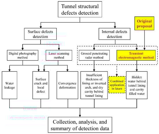
Figure 5.
Detection method of tunnel structural defects.
The surface defects tend to be concentrated on the surface of the lining structures and are easily detected. In contrast, the internal defects are usually located between the lining structure and the surrounding rock, which means that these internal defects are difficult to find. Therefore, the rapid detection of internal defects is a serious challenge for tunnel maintenance engineers.
In view of the limitations and shortcomings of current tunnel defect detection methods, it is urgent to find a new and rapid detection method in order to realize the rapid detection of the hidden and undiscovered water behind the tunnel lining and the cavity-filled water, so that the existing detection method of tunnel structural internal defects can be well supplemented and improved. In this condition, the application of a transient electromagnetic method to the detection of internal defects is fully and profoundly proposed by referring to the rapid detection of aviation TEM, as shown in Figure 5.
2.3. Principle and Process of Vehicle-Mounted Transient Electromagnetic Method
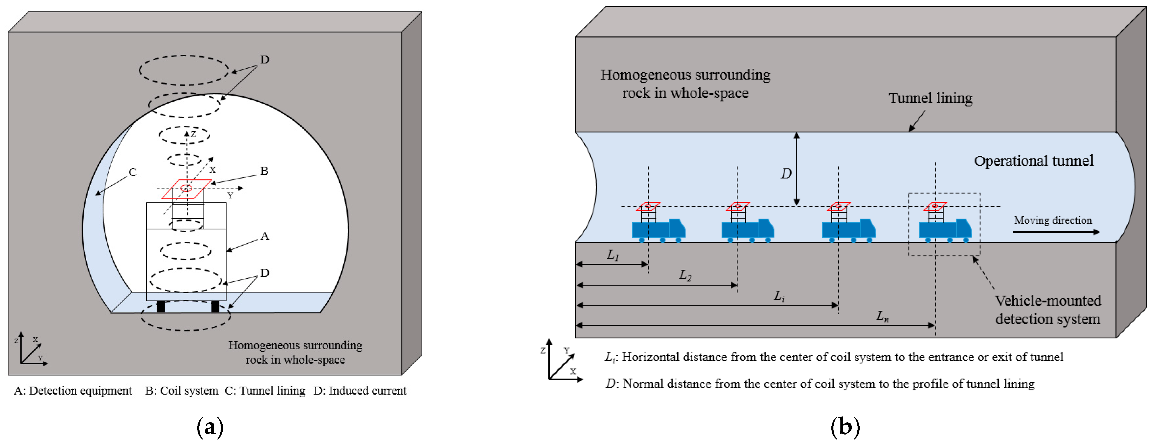
TEM technology can effectively distinguish the surrounding rock media based on the different electrical resistivity between the rock and water, and the development scale of the hidden and undiscovered water can also be assessed to some extent [3,9,17,18]. The principle and process of vehicle-mounted TEM can be shown in Figure 6. The vehicle-mounted TEM measurement system includes the transmitter–receiver coil system and the movable platform, as shown in Figure 6a.
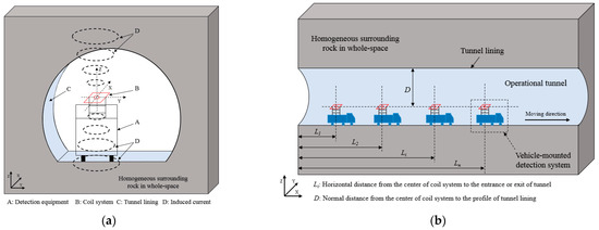
Figure 6.
Principle and process of vehicle-mounted transient electromagnetic method: (a) basic principle; (b) detection process.
In operational tunnels, the detailed detection process of the vehicle-mounted TEM measurement system can be shown in Figure 6b, and the vehicle-mounted TEM measurement system can realize the simultaneous operation of detection and movement. The detection process of the vehicle-mounted TEM measurement system mainly consists of two steps, and the two steps are interlaced with each other [3]. For the first step, the transient pulse signal in the transmitter coil is instantly sent to the whole space of surrounding rock, and the receiver coil captures the second signal caused by the surrounding rock. For the second step, the movable platform moves quickly through the tunnel, and its position condition is recorded. It is important to note that the movable platform is not recommended to be made of metal, to avoid ineffective electromagnetic signals. Based on these two steps, the induction signal and position information of the entire tunnel can be acquired, and so the spatial information map of the tunnel defects in the entire tunnel can be identified and obtained through the fast inversion method.
3. Verification of Theoretical Analysis and Numerical Simulation
3.1. Homogeneous Half-Space Medium
According to the principle of the transient electromagnetic method, the secondary magnetic field of the homogeneous half-space medium is shown in Formula (1). In this case, the nonlinear features of the media are not considered in order to verify the feasibility of the detection method.
where is the secondary magnetic field component in the direction of the spherical coordinate system (A/m), is the magnetic dipole moment (A·m2), and are the components of the spherical coordinate system, is the probability integral and its expression is , is the electromagnetic field time (s), is the judgment coefficient of time or distance of electromagnetic field and its expression is , and is the resistivity of the medium (Ω·m).
Two methods are used to verify the results of the electromagnetic field in a three-dimensional homogeneous half-space model. The first method is an analytical solution based on Formula (1), which is self-programming. The other method is the simulation solution, which uses electromagnetic field common software.
In the analytical solution, the fast Hankel transform of 47 point filter coefficients can be used to solve the integral of the zero-order or first-order Bessel function in the transient electromagnetic field, and can be realized by MATLAB self-programming. In the process of calculation, the radius and turn of the transmitter coil are 20.0 m and 1, respectively. As for the ideal negative step, the maximum current of the transmitter coil is 1.0 A. The resistivity of the medium is 1000 Ω·m, and the radius and turn of the receiver coil is 0.01 m and 100, respectively. It should be noted that the radius of the transmitter coil in the analytical solution needs to be set large enough to ensure the high precision of the secondary magnetic field at the center of the coil. For the receiver coil, since the analytical calculation is linear, the coil form has no more limitations in the analytical calculation.
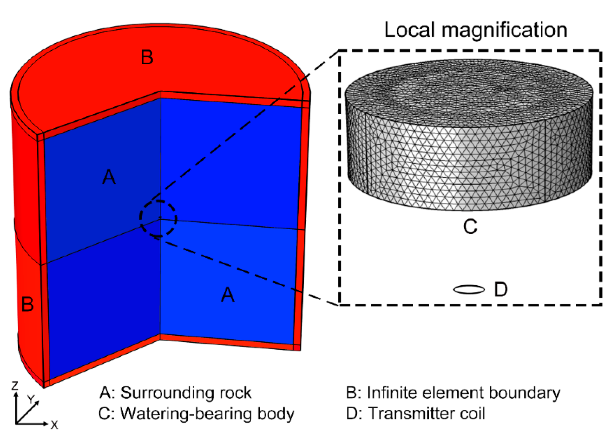
In the simulation solution, a three-dimensional half-space model is adopted in the COMSOL software (Version 5.4), the center of the excitation coil is located at the center point of the three-dimensional model, and the normal direction of the transmitter coil is perpendicular to the X-Y plane of the Cartesian coordinate system [3]. The model is a cylindrical structure with a radius of 400 m and a height of 800 m. The upper part of the model is a surrounding rock medium with a resistivity of 1000 Ω·m, and the lower part is an air medium with a resistivity of 1,000,000 Ω·m. The infinite element is adopted at the boundary of the model, and its thickness is 20 m. The parameters of the coil in the simulation model are the same as the analytical solution method. The detailed model can be shown in Figure 7 [3].
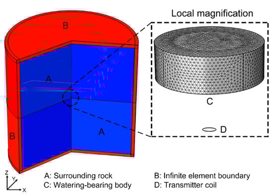
Figure 7.
Layout of finite element model.
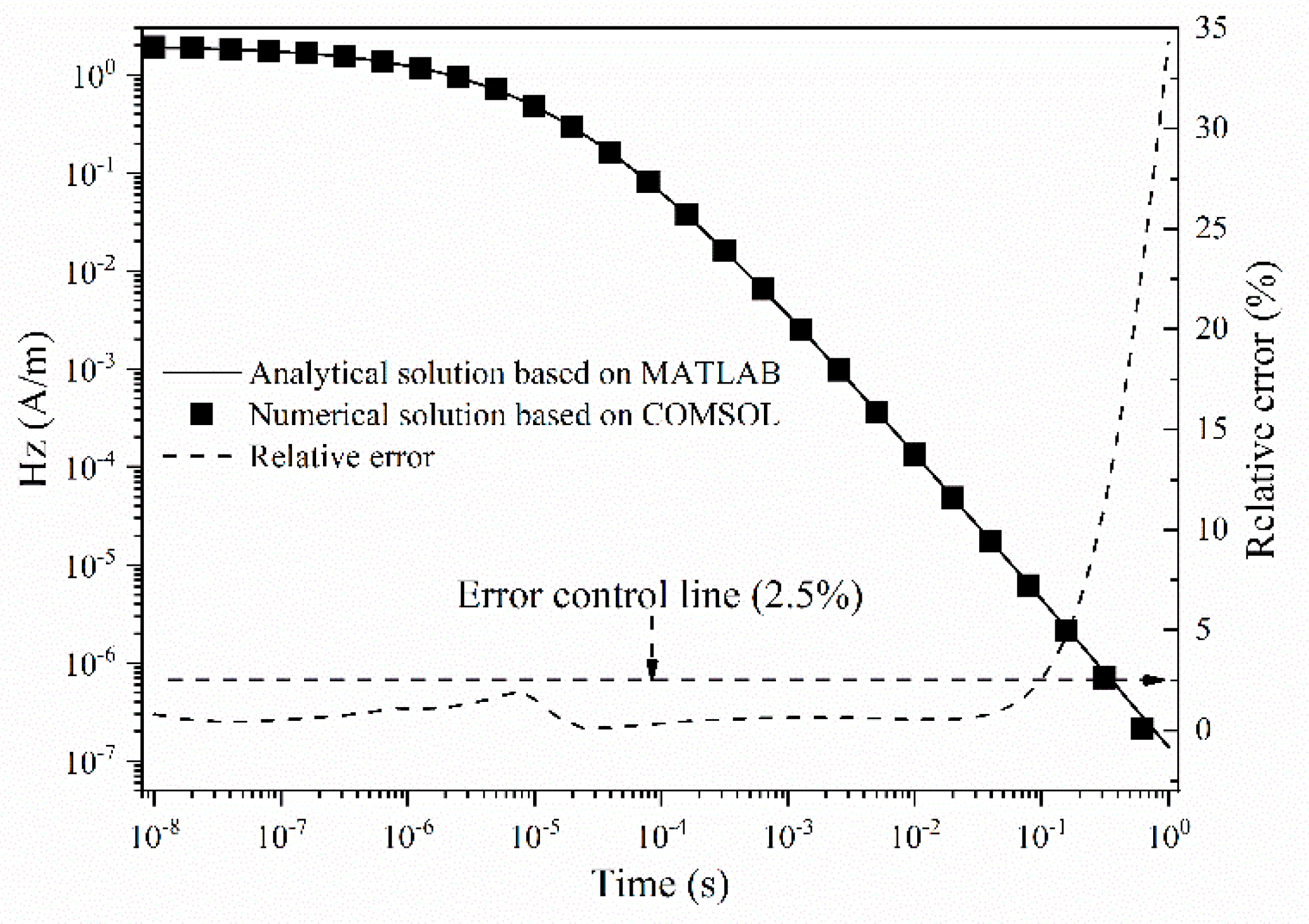
Through the calculation of the two methods, the numerical solution based on COMSOL and the analytical solution based on MATLAB can be obtained, and the results are shown in Figure 8. In order to compare the accuracy of the numerical solution and analytical solution, the relative error between them is also calculated, as shown in Figure 8.
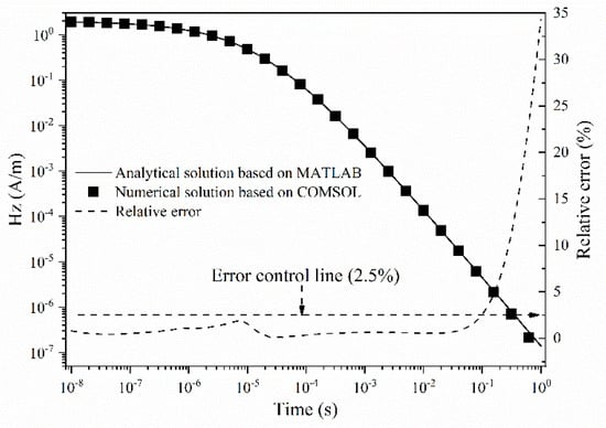
Figure 8.
Calculation results and relative error of two methods.
It can be seen from Figure 8 that the numerical solution curve of the transient electromagnetic field in the three-dimensional half-space medium is consistent with the analytical solution curve. In general, the response curve of the secondary magnetic field exhibits an obvious linear attenuation trend in the middle and late stages. As shown in Figure 8, the relative error of both the numerical solution and the analytical solution is no more than 2.5%, except for the calculation results when the time is greater than 0.1 s. To sum up, the calculation result between the numerical and the analytical solution is consistent under the error tolerance condition. Therefore, the numerical simulation results based on COMSOL are reliable and accurate, and can well reflect the internal physical law of the transient electromagnetic response in the three-dimensional half-space medium to some extent.
3.2. Inhomogeneous Whole-Space Medium
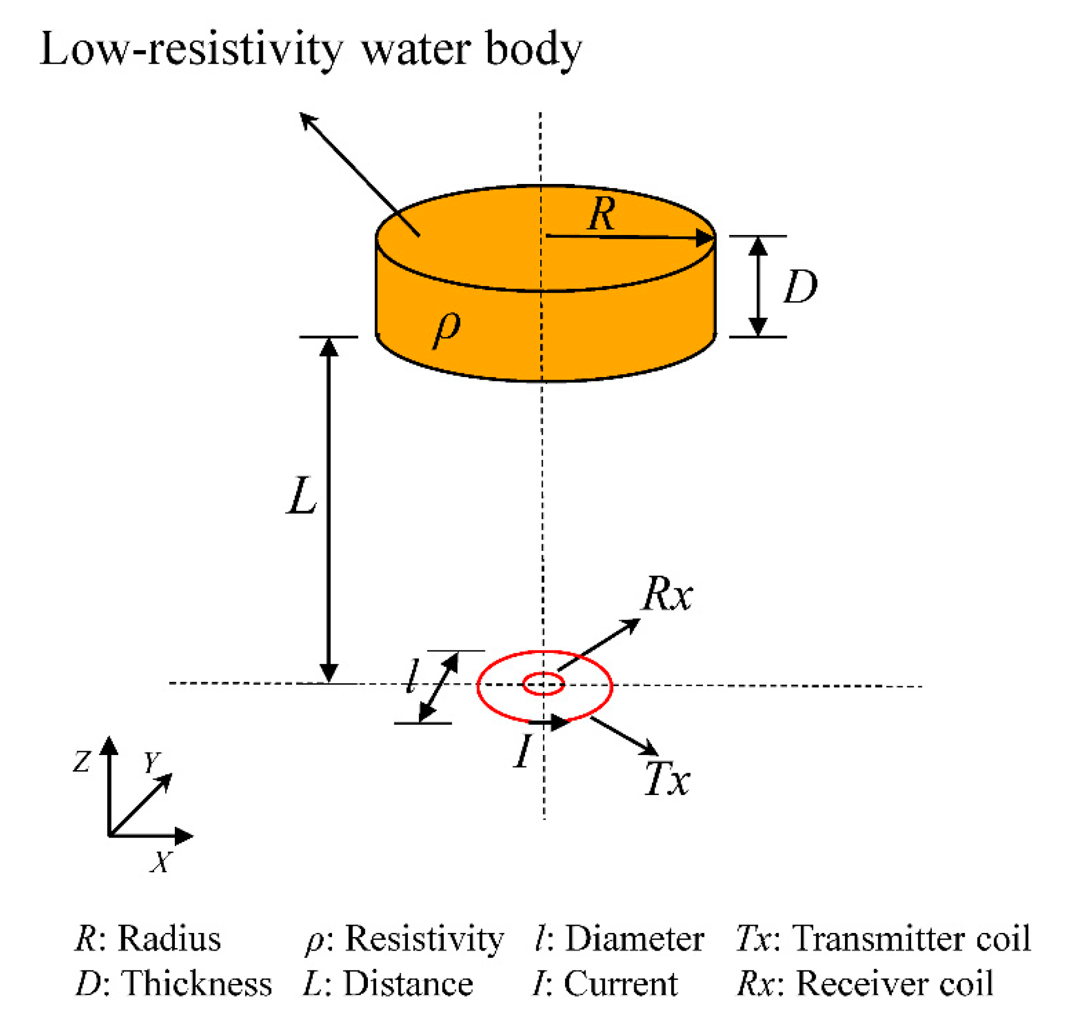
For vehicle-mounted transient electromagnetic detection, the medium exists simultaneously in the front and back of the transmitter coil, which is a whole-space problem. When there is a water body with low resistivity directly in front of the transmitter coil, it can be simplified into a flat cylinder, as shown in Figure 9 [3]. This condition is called inhomogeneous whole-space as opposed to homogeneous whole-space. In this case, the shape of the water body is simplified in order to perform fast three-dimensional forward computation.
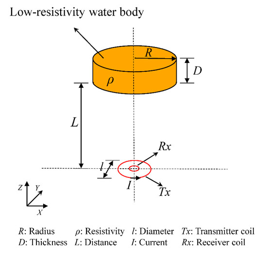
Figure 9.
Layout and dimensions of vehicle-mounted TEM coil and water-bearing body.
As for the inhomogeneous whole-space medium, it is a local medium with a finite size in the whole medium, but it is not a layered medium. Hence, the general form of the electromagnetic field analytical solution is difficult to obtain compared with the layered theory. Based on the conclusions of Section 3.1, the numerical solution based on COMSOL is consistent with the analytical solution based on MATLAB, so the numerical solution based on COMSOL is also used to describe and explain the law of the secondary magnetic field in the inhomogeneous whole-space medium.
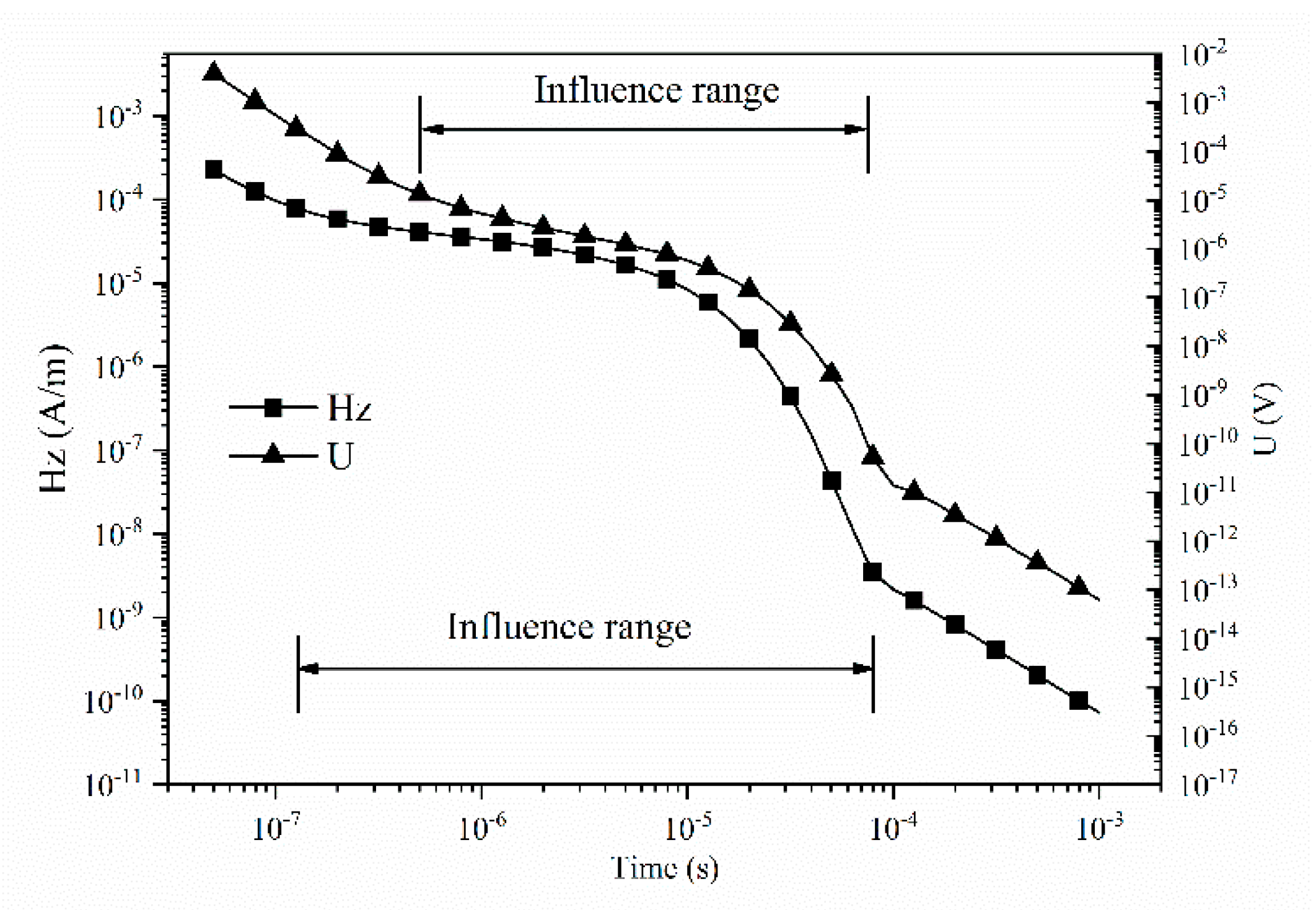
Based on the numerical solution model in Section 3.1, a water body model with low resistivity is added in front of the transmitter coil, as shown in Figure 7 and Figure 9. The upper and lower parts of the transmitter coil are surrounding a rock medium with a resistivity of 1000 Ω·m, and the water body with low resistivity is assumed to be 5 Ω·m [3,6]. The distance between the water body with low resistivity and the coil is 5 m, and the radius and thickness of the water body are 4.0 m and 0.3 m, respectively. Meanwhile, the size of the coil is also redesigned to be combined with the characteristics of vehicle-mounted transient electromagnetic detection [19]. The radius and turn of the transmitter coil are 0.5 m and 20, respectively. As for the ideal negative step, the maximum current of the transmitter coil is 1.0 A. The area and turn of the receiver coil are 0.0001 m2 and 20, respectively. Taking the secondary magnetic field at the center of the transmitting coil and the induced voltage of the receiver coil as the analysis target, the transient electromagnetic response under the condition of three-dimensional inhomogeneous whole-space is carried out, and the calculated results are shown in Figure 10.
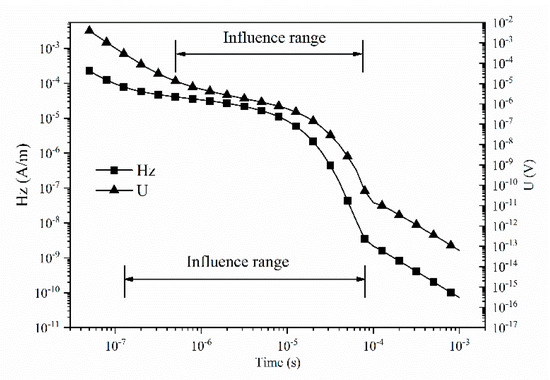
Figure 10.
Response curve under the condition of three-dimensional inhomogeneous whole-space.
As shown in Figure 10, the secondary magnetic field and the induced voltage exhibit a nonlinear attenuation trend in the double logarithmic coordinates. The transient electromagnetic response curve can be qualitatively divided into three stages: early, middle, and late. Taking the response curve of the secondary magnetic field as an example, the response curve shows linear attenuation at the early and late stages, while the attenuation velocity of the response curve increases first and then decreases at the middle stages. By comparing the response curves of the secondary magnetic field and induced voltage, it can be seen that the influence range of nonlinear attenuation is not consistent. On the whole, the influence range of the secondary magnetic field is larger than that of the induced voltage, and the start time of the secondary magnetic field is earlier than that of the induced voltage, which is consistent with the conclusion of many application fields of the transient electromagnetic method.
3.3. Comparison of Homogeneous and Inhomogeneous Whole-Space Medium
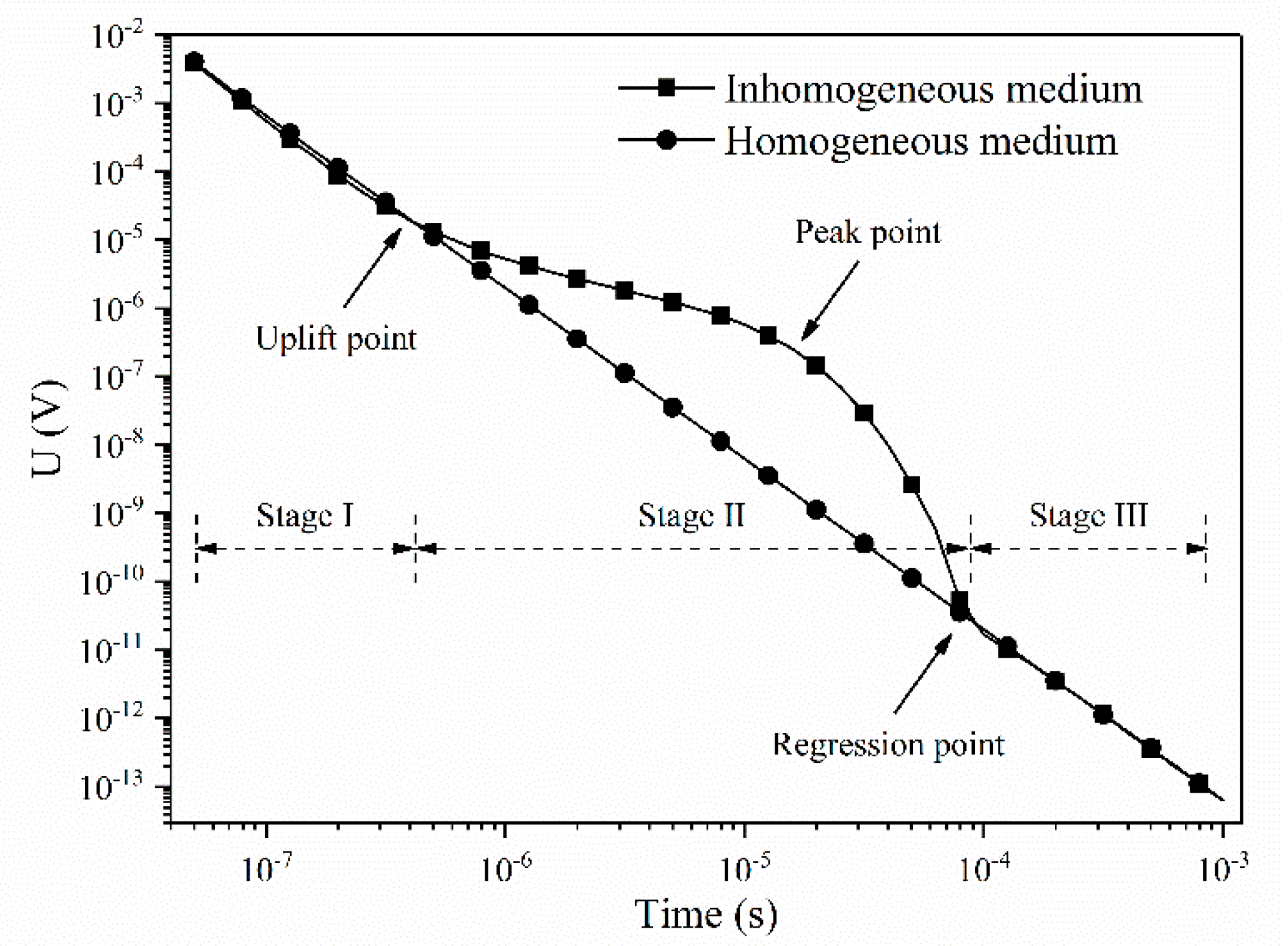
Based on the above analytical and numerical results, the response curve presents different attenuation laws in different media. Taking the induced voltage of the receiver coil as an example, the numerical simulation results of homogeneous and inhomogeneous whole-space media under the three-dimensional condition can be obtained, as shown in Figure 11. As for the homogeneous whole-space medium, the transient electromagnetic response results can be calculated by modifying the resistivity of the water body to the resistivity of surrounding rock.
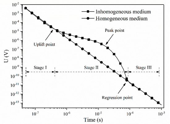
Figure 11.
Comparison of homogeneous and inhomogeneous whole-space medium.
By comparing the response curve of the inhomogeneous and homogeneous whole-space medium, there are obvious differences between the two response curves, and it can be quantitatively divided into three stages according to the response time. In Stage I, the induced voltage amplitude in the inhomogeneous whole-space medium is slightly smaller than that in the homogeneous whole-space medium, the difference between the values is not very large, and both of the response curves almost maintain the same attenuation rate. In Stage II, the induced voltage amplitude in the inhomogeneous whole-space medium is larger than that in the homogeneous whole-space medium, and the difference between the values is dynamic. At the same time, the difference between the inhomogeneous and homogeneous whole-space medium increases first and then decreases, which means that the attenuation rate of the response curve in the inhomogeneous whole-space medium illustrates the same trend. The difference level, defined as the logarithm of the value in the inhomogeneous whole-space medium divided by the value in the homogeneous whole-space medium, is greater than zero, and its maximum value can reach up to 2.11. In Stage III, the induced voltage amplitude in the inhomogeneous whole-space medium is almost equal to that in the homogeneous whole-space medium, and both of the response curves keep the same attenuation rate again.
Judging from the phenomenon depicted in Figure 11, three key points of the response curve in the inhomogeneous and homogeneous whole-space medium can be obtained. The first point is the uplift point, and its time is approximately 0.4 us, which is at the end of Stage I and the beginning of Stage II. The uplift point exhibits that the amplitude of the response curve in the inhomogeneous whole-space medium is about to exceed the amplitude of the response curve in the homogeneous whole-space medium, and it also indicates that the diffusion of the induced eddy begins to transform from the surrounding rock to the water body with low resistivity. The second point is the peak point, and its time is approximately 16 us, which is somewhere in the middle of Stage II. The peak point demonstrates that the amplitude of the response curve in the inhomogeneous whole-space medium reaches the maximum relative to the amplitude of the response curve in the homogeneous whole-space medium at the same time, which means that the induced eddy is mainly concentrated on the water body with low resistivity and its amplitude reaches the relative maximum. The third point is the regression point, and its time is approximately 80 us, which is at the end of Stage II and the beginning of Stage III. The regression point shows that the amplitude of the response curve in the inhomogeneous whole-space medium is about to tend the amplitude of the response curve in the homogeneous whole-space medium, which illustrates that the diffusion of the induced eddy begins to transform from the water body with low resistivity to the surrounding rock.
To summarize, the diffusion law of the secondary magnetic field in the homogeneous half-space medium is investigated through two different methods, including theoretical analysis and numerical simulation. Furthermore, the rationality and accuracy of the numerical simulation are verified. Meanwhile, the electromagnetic response characteristics of the inhomogeneous medium and homogeneous whole-space medium are investigated based on numerical simulation, so the obvious difference between the response curves of the inhomogeneous and homogeneous whole-space medium is also proved.
4. Laboratory Experiment
4.1. Experiment Design
According to the similarity criterion of transient electromagnetic method, the basic similarity criterion is obtained as shown in Formula (2), and the additional similarity criterion is expressed as shown in Formula (3).
where and represent the prototype and model, respectively, and are the conductivity of the prototype and model, respectively, is the geometric similarity ratio between the prototype and the model, and is the time similarity ratio between the prototype and the model.
where and are the induced voltage and emission current in different models, respectively, and are the turn of transmitter coil and receiver coil, respectively, and are the length of transmitter coil and receiver coil, respectively, and and are the ratio factor of electric field and magnetic field between the prototype and the model, respectively.
In the laboratory experiment, the same transient electromagnetic instrument is adopted, so the time of the two models is consistent. The time similarity ratio is equal to 1, and Formula (2) can be simplified as , which indicates that the geometric similarity is the main control condition of basic similarity criterion.
Formula (3) describes the proportional relationship between the observed data of the prototype and the model. Since two ratio factors of electromagnetic field between the prototype and the model are assumed to be a fixed constant, the proportionality coefficient depends on the specific size of the transmitter coil and receiver coil. Therefore, the transmitter coil and receiver coil cannot be designed according to the geometric similarity, which brings significant convenience to the design of two coils in the laboratory experiment.
Based on the above two similarity criteria, the variation law of transient electromagnetic response curve in the prototype can be reflected by the transient electromagnetic response curve in the model, and only a certain coefficient ratio exists between the two conditions. In the door experiment, the geometric similarity ratio is set to 1, so the full-scale physical model experiment can be presented to meet the background field requirements of the site electromagnetic environment. Meanwhile, the shape of the two coils is square, the length of the transmitter coil and receiver coil is set to 500 mm and 250 mm, respectively, and the turn per coil is set to 5.
4.2. Measure Instrument
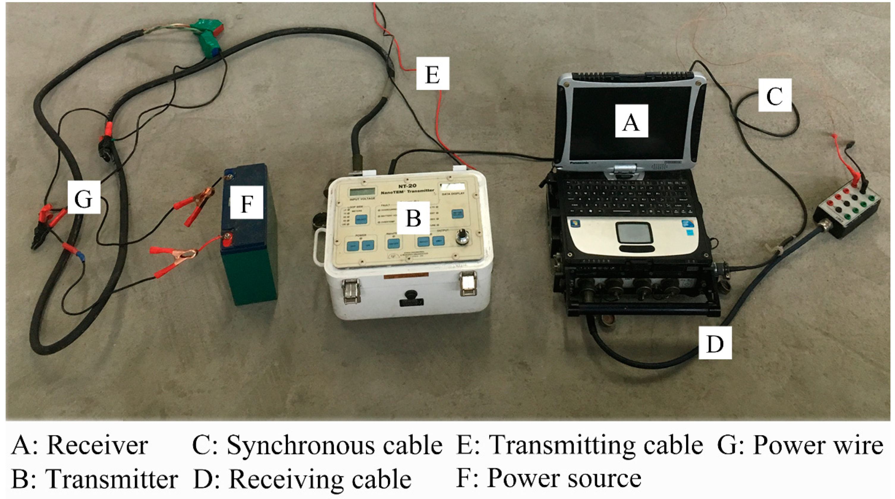
In the laboratory experiment, a set of high-precision transient electromagnetic instruments were selected and determined to measure electromagnetic induction signals, including a NANOTEM transmitter and a SM24 receiver, as shown in Figure 12.

Figure 12.
Indoor transient electromagnetic instrument.
The NANOTEM transmitter produced by the ZONGE Company (Tucson, AZ, USA) is a measurement method in the GDP-32 transient electromagnetic system. The current stability accuracy of the transmitter is less than 0.1% under the condition of low power, and its biggest advantage is that the cut-off time can be less than 1.0 us, which is very suitable for ultra-shallow transient electromagnetic measurement. The SM24 receiver produced by the EMIT Company (Perth, Australia) is the world’s true 24-bit transient electromagnetic receiver, which can record the whole time data and collection sequence. Each interface of the receiver can control four channels and each channel has a separate 24-bit ADC and amplifier, so it can realize the function of multi-component or multi-directional simultaneous measurements to ensure the independence of multiple measurement data. The receiver is compatible with any transmitter and transient electromagnetic probe or user-defined receiver wireframe, which provides a significant basis for the design of the transmitter equipment and the coil. Therefore, it can be seen that the selection of measure instrument in the laboratory experiment is a combination of the most outstanding performances of the NANOTEM transmitter and SM24 receiver.
4.3. Experiment Procedure
The procedure step of laboratory experiment mainly includes coil design, saline water configuration, bag installation, and coil arrangement. The detailed process is shown in Figure 13.
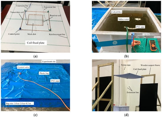
Figure 13.
The detailed process of laboratory experiment: (a) transmitter coil and receiver coil; (b) configured saline water; (c) customized plastic bag; (d) relative position of coil.
Depending on the characteristics of vehicle-mounted transient electromagnetic detection, the size of coils in the laboratory experiment is also redesigned. The length of the transmitter coil and receiver coil is 500 mm and 250 mm, respectively, and the turn per coil is 5. The shapes of the transmitter coil and the receiver coil are fastened by four control points and a mesh disk, and both coils are placed on the plastic fixed plate. Both coils are connected to the transient electromagnetic instrument via an extension line, and the coil fixed plate with certain flexibility is reinforced by the plastic reinforcement line. The detailed layout of two coils is shown in Figure 13a.
The saline water with a concentration of 5% at 25 degrees Celsius is pre-configured, as shown in Figure 13b. Water with a volume of 950 L is added to the cuboid box through a PVC pipe, and sodium chloride solid with a weight of 50 kg is also added. After the solid salt is fully dissolved, the resistance of the solution is measured by the U-type pipe and multimeter, and the resistivity of solution can be further converted. If the resistivity does not meet the requirements, the weight of sodium chloride or the volume of water can be adjusted appropriately to achieve the design value of solution.
The customized plastic bag is laid horizontally on the ground, as shown in Figure 13c. The specified volume of saline water can be injected into the bag through the PVC pipe and control valve. The horizontal dimension of the bag is 3.0 m × 3.0 m (length × width), and the maximum vertical dimension of the bag can reach to 0.3 m (height) when the bag is fully filled with saline water. In this verification experiment, the bag was injected with appropriate saline water to achieve a thickness of 0.2 m.
The coil fixed plate is arranged directly above the bag, as shown in Figure 13d. The coil fixed plate is hoisted on two wooden support frames by four nylon ropes. The distance between the coil fixed plate and the customized plastic bag can be adjusted by the nylon rope, and its maximum value can reach up to 4.0 m. In this verification experiment, the distance between the plate and bag was set as 3.0 m in order to reflect the short-distance characteristic of vehicle-mounted transient electromagnetic method.
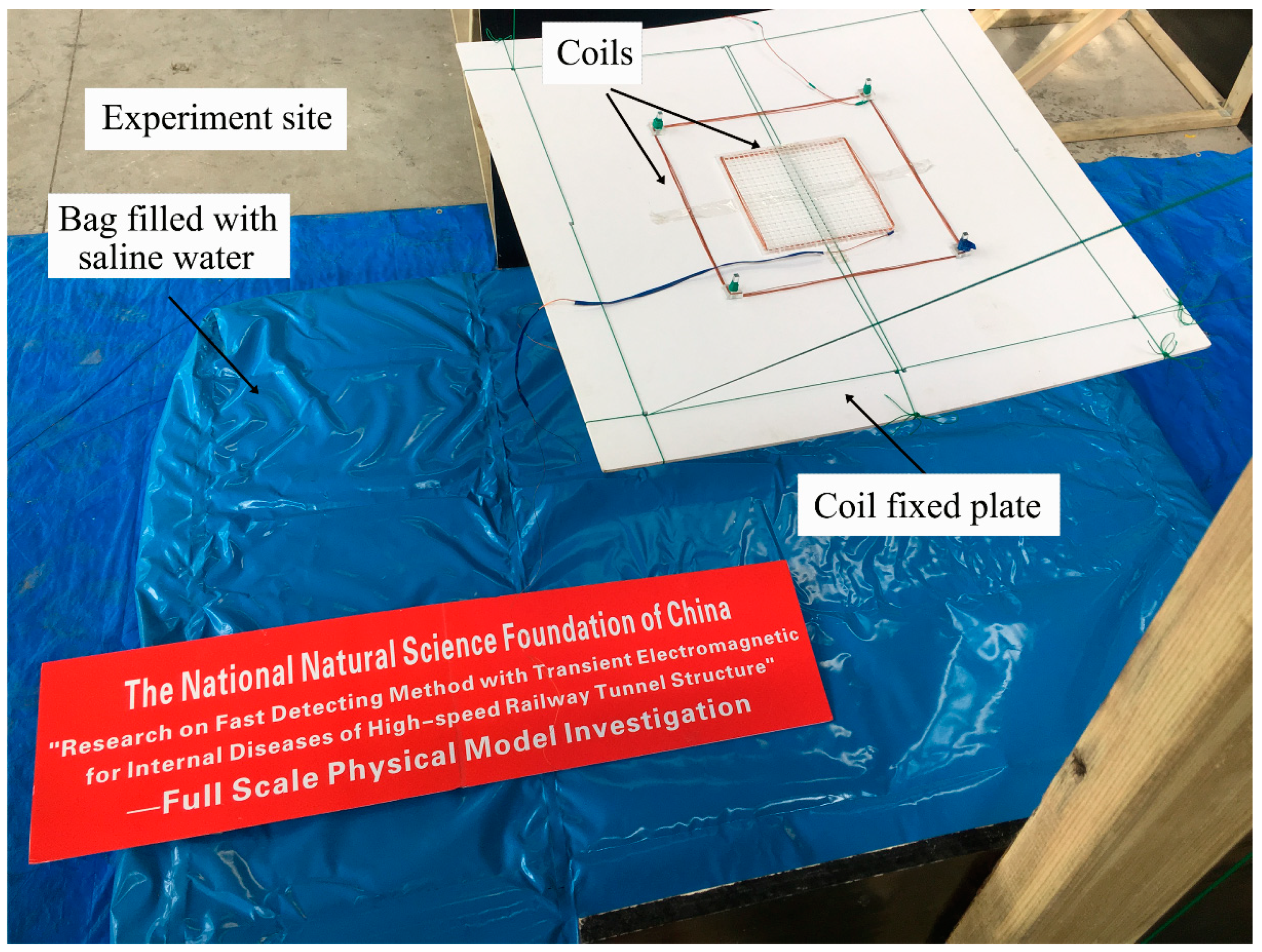
Through the above four steps, combined with the selection of transient electromagnetic instrument, the measurement of transient electromagnetic is carried out in the half-space medium. The final layout of laboratory experiment is illustrated in Figure 14.
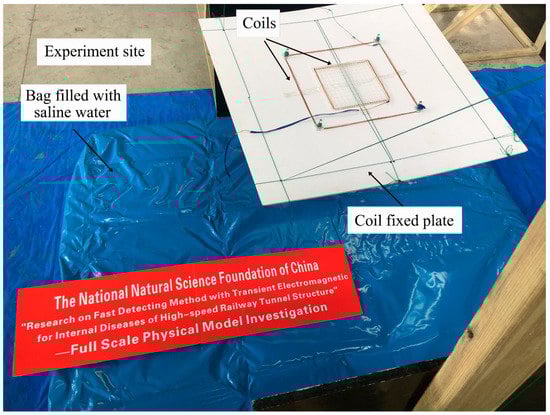
Figure 14.
The final layout of laboratory experiment.
4.4. Experiment Result and Inversion
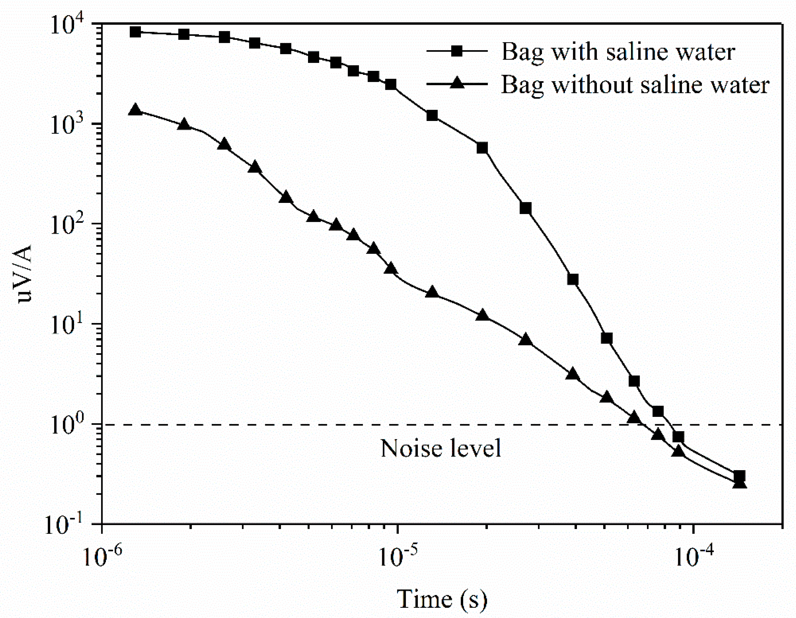
During the experiment, the vertical distance between the plastic fixed plate and customized plastic bag was 3.0 m, and the electromagnetic field responses of two conditions were measured. The first condition is that the height of saline water in the bag is 0.3 m, which indicates that there is a water body with low resistivity in the indoor electromagnetic background field. The second condition is that there is no saline water in the bag, which manifests that the response of the indoor electromagnetic background field is measured. In the laboratory experiment, it is difficult to reproduce field conditions; namely the hidden water behind tunnel linings. Thus, the equivalent method is adopted in order to implement the field simulation. There may be some difference in the numerical accuracy between the results of the laboratory experiment and the actual field situation, but the actual field situation can also be qualitatively verified by the laboratory experiment to some extent. The normalized transient electromagnetic response results under the two conditions are illustrated in Figure 15.
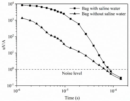
Figure 15.
Normalized transient electromagnetic response results under the two conditions.
As shown in Figure 15, there are obvious differences in the transient electromagnetic response curves under the two conditions. The response curve of the bag without saline water presents linear attenuation in the double logarithmic coordinate, while the response curve of the bag with saline water illustrates nonlinear attenuation. On the whole, the induced voltage amplitude of the bag with saline water is greater than that of the bag without saline water. Meanwhile, the difference between the two response curves increased first and then decreased. Therefore, the response results of the laboratory experiment are close to the results of the theoretical analysis and numerical simulation as a whole.
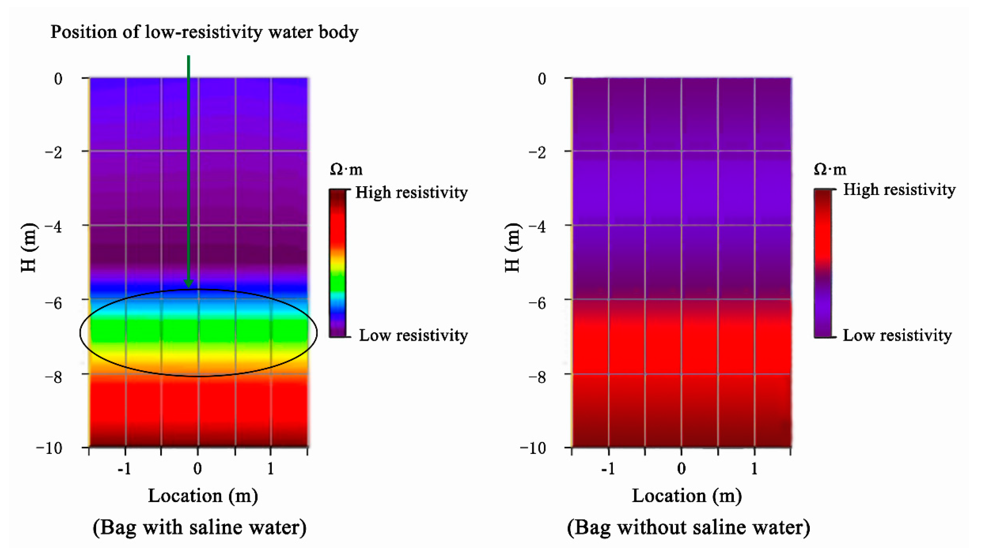
Based on the measurement results of the laboratory experiment, selecting the single point measurement as the analysis object, the transient electromagnetic response signal is inverted by the inversion software of EMIT MAXWELL, and the inversion result can be obtained as shown in Figure 16.

Figure 16.
Apparent resistivity map of laboratory experiment measure results.
By comparing the apparent resistivity in the two conditions, as shown in Figure 16, it can be determined that there is a region with low resistivity in front of the transmitter coil. Therefore, it can be preliminarily determined that there is a potential water body with low resistivity in front of the transmitter coil, and it also conforms to the position relation of the bag with saline water in the laboratory experiment. Due to the interference of the two coils and the performance of the measurement instrument, the early measurement data cannot be directly used for the transient electromagnetics inversion, and the time gate that can be used to invert the measurement data is later than the time gate requirements for theoretical analysis and numerical simulation. Therefore, the results of the apparent resistivity in the vicinity of the transmitter coil cannot be used to evaluate the position of the water body with low resistivity; that is, there is a certain inversion blind zone, and the blind range is approximately 4 m to 5 m. In the laboratory experiment, the vertical distance between the bag with saline water and the transmitter coil is 3.0 m, while the inversion apparent resistivity map illustrates that there is a water body with low resistivity in the range of 5 m to 8 m in front of the transmitter coil. Therefore, the inversion results can qualitatively verify the theoretical research and numerical simulation results of the vehicle-mounted transient electromagnetics method.
5. Discussion
The physical parameters of the two coils and water body with low resistivity were assumed in advance during the laboratory experiment. In the subsequent laboratory experiment, the form of the two coils, including the turn and length, will be quantitatively investigated, and the shape and resistivity of the water body with low resistivity will also be further investigated.
Affected by the performance of the transient electromagnetic instrument and background electromagnetic noise, the measurement results of the laboratory experiment cannot be effectively used for inversion in the early and late time, so the inversion results of the laboratory experiment cannot truly reflect the position relationship between the actual surrounding rock and the water body with low resistivity. There is a certain depth of blind zone in the inversion results, while the position relationship of the short-distance water body with low resistivity can still be qualitatively inferred. However, this qualitative inference also has a certain blindness and subjectivity. If the judgment is incorrect, it may lead to incorrect inversion results.
In order to ensure the applicability of the vehicle-mounted transient electromagnetic method in operating tunnels, optimizing the form of the two coils and improving the performance of the measurement instrument are extremely important. Obviously, these methods can significantly reduce the turn-off time of the instrument and improve the late signal-to-noise ratio of the acquired signal. Simultaneously, the inversion technology of the vehicle-mounted transient electromagnetic method also needs to be further optimized and improved due to different space conditions.
6. Conclusions
The vehicle-mounted transient electromagnetic method is fully and perfectly proposed, and it aims to realize the rapid detection of internal defects of operational tunnels. The main results are summarized as follows.
- (1)
- Based on the investigation of tunnel defects, the internal defects, especially the hidden and undiscovered water behind the tunnel lining, are the main origin of many tunnel defects, and directly affect the normal operation state of the tunnel;
- (2)
- Aimed at the rapid detection of tunnel defects, a new type of detection technology called the vehicle-mounted transient electromagnetic method is proposed. This detection technology is a promising application of a transient electromagnetic method in tunnel defect detection, and its principle is also based on the obvious resistivity difference between tunnel defects and surrounding rocks;
- (3)
- The rationality of the simulation solution of the secondary magnetic field of the homogeneous half-space medium is verified by the fast Hankel transform. Based on the typical whole-space case, the transient electromagnetic response characteristics of the inhomogeneous medium are obviously different from those of the homogeneous medium, especially in the middle stage of the electromagnetic response curve;
- (4)
- Based on the similarity criterion of the electromagnetic field, a set of saline water model experiments are designed. As a whole, the induced voltage amplitude of the bag with saline water is greater than that of the bag without saline water, so the attenuation trend of the electromagnetic response measured in the experiment is consistent with the results of the theoretical analysis and numerical simulation;
- (5)
- According to apparent resistivity inversion results, the low resistivity region revealed in front of the transmitter coil can reflect the existence of a potential water body with low resistivity to some extent. Meanwhile, the distance obtained from the inversion essentially conforms to the distance in the experiment, considering the existence of the inversion blind zone. Therefore, the inversion results can qualitatively verify the rationality of the vehicle-mounted transient electromagnetic method.
Author Contributions
Conceptualization, W.Q.; Formal analysis, H.L.; Funding acquisition, Z.G.; Investigation, J.Y.; Methodology, W.Q., H.L. and Z.G.; Resources, Z.G.; Software, J.Y.; Supervision, W.Q. All authors have read and agreed to the published version of the manuscript.
Funding
This work was supported by The National Natural Science Foundation of China (grand No. 51808298), Jiangsu Province College Students’ innovation and entrepreneurship training program (grand No. 202110304115Y), Natural Sciences Fund for Colleges and Universities in Jiangsu Province (grand Nos. 20KJB560036 and 20KJD560002), and Nantong Science and Technology Plan Project (grand Nos. JC2020122 and JC2020124).
Institutional Review Board Statement
Not applicable.
Informed Consent Statement
Not applicable.
Data Availability Statement
The data used to support the findings of this research are available from the corresponding author upon request.
Acknowledgments
The authors would like to equally thank Wenjing Lu from the Xuzhou Economic Development Zone Industrial School, China, for linguistic assistance during the preparation of this manuscript. The insightful comments and significant suggestions from the anonymous reviewers of Applied Sciences are sincerely appreciated.
Conflicts of Interest
The authors declare that there are no conflicts of interest.
References
- Asakura, T.; Kojima, Y. Tunnel maintenance in Japan. Tunn. Undergr. Space Technol. 2003, 18, 161–169. [Google Scholar] [CrossRef]
- Montero, R.; Victores, J.G.; Martínez, S.; Jardón, A.; Balaguer, C. Past, present and future of robotic tunnel inspection. Autom. Constr. 2015, 59, 99–112. [Google Scholar] [CrossRef]
- Qian, W.; Qi, T.; Liang, X.; Qin, S.; Li, Z.; Li, Y. Vehicle-Borne Transient Electromagnetic Numerical Characteristic Parameter of Water-Bearing Body behind Tunnel Linings. Math. Probl. Eng. 2020, 2020, 8514913. [Google Scholar] [CrossRef] [Green Version]
- Shi, D. Research on Quality Defects and Safety Evaluation Standard of New-Built High-Speed Railway Tunnel Lining. Doctoral Dissertation, Beijing Jiaotong University, Beijing, China, 2018. [Google Scholar]
- JTG H12-2015. Technical Specifications of Maintenance for Highway Tunnel; China Communications Press: Beijing, China, 2015. [Google Scholar]
- Li, Y.; Qi, T.; Lei, B.; Li, Z.; Qian, W. An iterative inversion method using transient electromagnetic data for water-filled cave prediction during tunnel construction. Geophysics 2019, 84, 89–103. [Google Scholar] [CrossRef]
- Swidinsky, A.; Weiss, C.J. On coincident loop transient electromagnetic induction logging. Geophysics 2017, 82, E211–E220. [Google Scholar] [CrossRef]
- Liang, X.; Qi, T.; Jin, Z.; Qian, W. Hybrid support vector machine optimization model for inversion of tunnel transient electromagnetic method. Math. Biosci. Eng. 2020, 17, 3998–4017. [Google Scholar] [CrossRef] [PubMed]
- Li, Z. Research on Vehicle-Borne Transient Electromagnetic Hardware Arrangement and Parameter for Internal Defects of High-Speed Railway Tunnel Structure. Doctoral Dissertation, Southwest Jiaotong University, Chengdu, China, 2021. [Google Scholar]
- Xue, Y.; Cai, X.; Shadabfar, M.; Shao, H.; Zhang, S. Deep learning-based automatic recognition of water leakage area in shield tunnel lining. Tunn. Undergr. Space Technol. 2020, 104, 103524. [Google Scholar] [CrossRef]
- Lei, M.; Liu, L.; Shi, C.; Tan, Y.; Lin, Y.; Wang, W. A novel tunnel-lining crack recognition system based on digital image technology. Tunn. Undergr. Space Technol. 2021, 108, 103724. [Google Scholar] [CrossRef]
- Cui, H.; Ren, X.; Mao, Q.; Hu, Q.; Wang, W. Shield subway tunnel deformation detection based on mobile laser scanning. Autom. Constr. 2019, 106, 102889. [Google Scholar] [CrossRef]
- Zan, Y.; Li, Z.; Su, G.; Zhang, X. An innovative vehicle-mounted GPR technique for fast and efficient monitoring of tunnel lining structural conditions. Case Stud. Nondestruct. Test. Eval. 2016, 6, 63–69. [Google Scholar] [CrossRef] [Green Version]
- Ling, T.H.; Liu, H.R.; Gong, S.W.; Huang, F. Construction and application of a new biorthogonal wavelet basis for a quantitative analysis of GPR signals. J. Appl. Geophys. 2019, 170, 103837. [Google Scholar] [CrossRef]
- Jin, Y.; Duan, Y. A new method for abnormal underground rocks identification using ground penetrating radar. Measurement 2020, 149, 106988. [Google Scholar] [CrossRef]
- Cassidy, N.J.; Eddies, R.; Dods, S. Void detection beneath reinforced concrete sections: The practical application of ground-penetrating radar and ultrasonic techniques. J. Appl. Geophys. 2011, 74, 263–276. [Google Scholar] [CrossRef]
- Marcys, W.G.; Bülent, T. Multi-dimensional interpretation of radiomagnetotelluric and transient electromagnetic data to study active faults in the Mygdonian Basin, Northern Greece. J. Environ. Eng. Geophys. 2016, 21, 121–133. [Google Scholar]
- Li, S.; Sun, H.; Lu, X.; Li, X. Three-dimensional modeling of transient electromagnetic responses of water-bearing structures in front of a tunnel face. J. Environ. Eng. Geophys. 2014, 19, 13–32. [Google Scholar] [CrossRef]
- Li, Z.; Qi, T.; Qin, S.; Qian, W. The research on minimizing the induction between the transmitting and receiving coils in close range transient electromagnetic inspection of groundwater-related defects in the operating tunnels. Math. Biosci. Eng. 2021, 18, 4508–4527. [Google Scholar] [CrossRef] [PubMed]

Publisher’s Note: MDPI stays neutral with regard to jurisdictional claims in published maps and institutional affiliations. |
© 2021 by the authors. Licensee MDPI, Basel, Switzerland. This article is an open access article distributed under the terms and conditions of the Creative Commons Attribution (CC BY) license (https://creativecommons.org/licenses/by/4.0/).