Article

On the Possibility to Use the Charge Imbalance in Patients Undergoing Radiotherapy: A New Online, In Vivo, Noninvasive Dose Monitoring System

1
Istituto Nazionale di Fisica Nucleare, Laboratori Nazionali del Sud, Via S Sofia 62, 95125 Catania, Italy
2
Dipartimento di Fisica ed Astronomia “E. Majorana”, Catania University, 95100 Catania, Italy
3
Centro Siciliano di Fisica Nucleare e Struttura della Materia (CSFNSM), 95125 Catania, Italy
4
AOU Policlinico of the University of Catania, 95123 Catania, Italy
5
Toret Devices s.r.l., 10153 Torino, Italy
6
Extreme Light Infrastructure (ELI)-Beamlines Center, Institute of Physics (FZU), Czech Academy of Sciences, 18221 Prague, Czech Republic
*
Author to whom correspondence should be addressed.
These authors contributed equally to this work.
Appl. Sci. 2021, 11(15), 7005; https://doi.org/10.3390/app11157005
Submission received: 9 May 2021 / Revised: 23 July 2021 / Accepted: 23 July 2021 / Published: 29 July 2021
(This article belongs to the Special Issue Applications of Medical Physics)

Abstract

:
This paper describes a new real-time, in vivo, noninvasive, biasless detector system acting as a beam monitoring and relative dose measurement system. The detector is based on the idea that when a beam current is injected into the body of a patient undergoing a charged particle therapy, the current itself can be collected using a conductive electrode in contact with the patient’s skin. This new approach was studied in vitro using an electrically isolated water tank irradiated with monoenergetic proton beams. The conductive electrode was immersed in water and positioned outside the irradiation field. The detection system performance was evaluated by comparing its response against a SEM (Secondary Emission Monitor) detector, used as a reference beam current monitor, and an Advanced Markus ionization chamber. Short-, mid- and long-term reproducibility, current monitoring capability, field size dependence, electrode position and environment temperature dependence, linearity with dose, and dose rate dependence were investigated. Few preliminary in vivo tests were also performed that demonstrated the possibility to apply the system in clinical practice. The potential of the proposed method is considerable, representing a simple and economical system for online, in vivo, and noninvasive monitoring of the beam current and relative released dose into the patient during treatment, without perturbing the irradiation field. The system presented in this work is protected with both a National Italian (N. 102017000087851) and an International N. WO 2019/025933 patent.

1. Introduction

In vivo dosimetry (IVD) represents a dosimetric procedure adopted in external beam radiotherapy (EBRT) to detect major errors, assess clinically relevant differences between planned and delivered doses, record doses received by individual patients, and to fulfill the legal requirements needed for a radiotherapy session. IVD is an essential element of modern radiation therapy, providing the ability to catch treatment delivery errors, assist in treatment adaptation, and record the actual dose delivered to the patient [1,2]. Moreover, IVD is becoming more strategic considering the new flash radiotherapy modalities [3], where potential errors could become even larger and more dangerous than in conventional approaches. It seems, in fact, worthwhile to investigate whether existing IVD detectors can be used for this purpose after determination of their dosimetric characteristics in very-high-dose-rate fields [4,5].
In vivo dosimetry involves several techniques and diversified approaches. All the dosimetric approaches currently adopted, are based on detectors intercepting and, therefore, somehow perturbing the irradiation field. This is of particular relevance in the case of charged particles radiotherapy, where energy losses and scattering effects are not negligible.
Thermoluminescent [6] or Radiochromic detectors [7] (off-line approach), silicon diodes [8,9,10], diamond detectors [11,12,13], and MOSFETs (Metal-oxide-semiconductor field-effect transistors) [14,15] (online approach) are conventionally used for in vivo dosimetry [16].
Thermoluminescent dosimeters [6] may be small in size and tissue equivalent but they require a long series of pre- and postirradiation processes and a calibration procedure to be used in the clinical practice. They are not off-line detectors nor usable for real-time dosimetry. Radiochromic films show an excellent spatial resolution; they are tissue equivalent, providing 2D dosimetric information. On the other hand, they are passive detectors, not allowing for real-time measurements. Moreover, their response may be affected by improper handling and scanner performances.
Silicon diodes are standard reference dosimeters for a variety of applications in radiotherapy including quality assurance in stereotactic modalities and in vivo dosimetry. Their major drawback lies in their relatively low radiation resistance, especially when used in charged particle beams.
Diamonds detectors present high sensitivity and spatial resolution comparable to that of silicon diode detectors, low leakage current, and high radiation hardness. On the other hand, some drawbacks limit their use such as high costs and, for the natural diamonds case, long delivery time due to suitable stone selection. Moreover, synthetic diamond detectors present some disadvantages (such as the control of type and amount of incorporated impurities) that seriously limit the production of detector-grade crystals and strongly affect the response stability.
The MOSFETs are able to achieve excellent spatial resolution because of their high sensitivity and small sensitive volume. In particular, the MOSkin, a patented dosimetry based on MOSFET technology and recently introduced by CMRP (Centre for Medical Radiation Physics, University of Wollongong, Australia), is also able to produce a real-time readout and provide a reproducible water equivalent depth of dose measurement of 0.07 mm (suitable for measurements of dose delivered on the patient’s skin) [17]. MOSFETs’ main disadvantages are finite lifetime (they can collect about 100 Gy as maximum), angular and energy dependence, and sensitivity change with accumulated dose. Moreover, MOSFETs do not provide real-time beam current monitoring. Their information on the dose is accessible only at the end of patient irradiation [18].
All the abovementioned devices can be positioned directly on the patient’s skin in order to provide information on the dose deposited but they all intercept and perturb the beam. Moreover, only diodes and diamond detectors are able to follow the beam current trend during the treatment in a real-time modality.
In this work, we will discuss the characteristics of an innovative detection approach for relative dose monitoring, based on the use of a simple and commercial electrode as that used in an electrocardiogram. We will call the name of this detector “Electrode”.
A patient undergoing a charged particle radiation treatment absorbs a well-defined quantity of charge and, therefore, is subjected to a net local charge imbalance. The charge disequilibrium generates a potential difference that will produce a current flow through an external, ground-based, floating electrode positioned on the patient’s skin, outside the radiation field. The current generated during the potential discharge is directed to a transimpedance, low-pass, and low-noise amplifier, acting as an high-precision picoamperemeter. The current is hence integrated. The measured charge corresponds to the net-deposited charge in the patient that can finally be connected to the absorbed dose. The Electrode system was characterized under the 62 MeV clinical monochromatic proton beams, available at the CATANA (Centro di AdroTerapia e Applicazioni Nucleari Avanzate) proton therapy facility of the Laboratori Nazionali del Sud (Istituto Nazionale di Fisica Nucleare) in Catania, Italy [19,20]. Moreover, preliminary tests were performed in vivo on patients undergoing ocular proton-therapy treatments. The tests demonstrated the clinical applicability of the approach as a beam current monitoring system and the possibility to use it for in vivo relative dose monitoring. The described “Electrode” technique can be extended to negative-charged beams, such as electrons, thus, covering the entire range of charged radiotherapy beams currently used.

2. Material and Methods

2.1. Low-Noise Acquisition Electronic

Electrode consists of a floating electrode (FIAB, model F2080) connected to a transimpedance, current–voltage converter amplifier, designed and realized by the authors of this paper. The currents collected by the electrode were of the order of nano-Ampere or a fraction of femto-Ampere, and the transimpedance gain was R = V o u t /I i n = 10 9 Ω . The amplified voltage signals were then sampled by a commercial high speed (1 MS/s) ± 10 V digital scope (model NI 9223, National Instruments). The acquisition software, able to monitor and register the currents and perform a preliminary analysis of the acquired signals, was also developed by the authors.
The trans-impedance amplifier contains four principal elements:
  • A current–voltage converter (I–V), based on an OPA128 (Texas Instruments) operational amplifier, coupled with a high-resistance feedback resistor (1 G Ω ) and a 100-pF capacitor, in parallel to the resistance. This configuration limits the maximum cutting frequency to 1.6 Hz; moreover, it allows the control of the autoinduced oscillations in the converter and avoids overshoot phenomena. The I–V converter response is linear in the output range of −10 V ≤ V o u t ≤ +10 V. The conversion range will hence be -10 nA ≤ I i n ≤ +10 nA.
  • A low-pass filter made of a Resistive-Capacitance (RC) network, with a cut frequency of 0.9 Hz and an attenuation of −68 dB at 50 Hz. The filter has two main roles: it protects the OPA128 operational amplifier from possible electrostatic discharges (ESD) induced both by patient and/or medical personnel during the pretreatment phases; it also weakens the 50-Hz noise currents, induced in the patient by the environment’s electromagnetic fields, by a factor 2.500.
  • A couple of Junction gate Field-Effect Transistors (JFET), which protect the OPA128 whenever the I–V converter reaches saturation. If the I–V converter works inside its operational range, the two JFETs are not operative and the leakage currents they introduce are negligible (order of 100 fA).
  • An active, inverting, second-order, low-pass filter. Its main aim is to cut (with a slope of 40 dB per decade) the residual noise at the output of the I–V converter. The inverting characteristic of this filter was designed to compensate the negative voltage sign at the output of the I–V converter. With this solution, the final output voltage will be positive, i.e., of the same sign as the input current.

2.2. Experimental Set-Up

Irradiations were performed at the INFN-LNS clinical proton therapy facility where a 62 ± 0.3 MeV proton beam was available. Details on the irradiation beamline, beam characteristics, and dosimetric procedures can be found elsewhere [19,20,21].
All measurements were performed by positioning the floating electrode inside a 20 × 20 × 20 cm 3 water tank, on the opposite side of the beam entrance window (see Figure 1) outside the irradiation field. The water tank was electrically isolated to avoid charge leakages. The beam spot size was circular, with a 25-mm diameter (Figure 1).
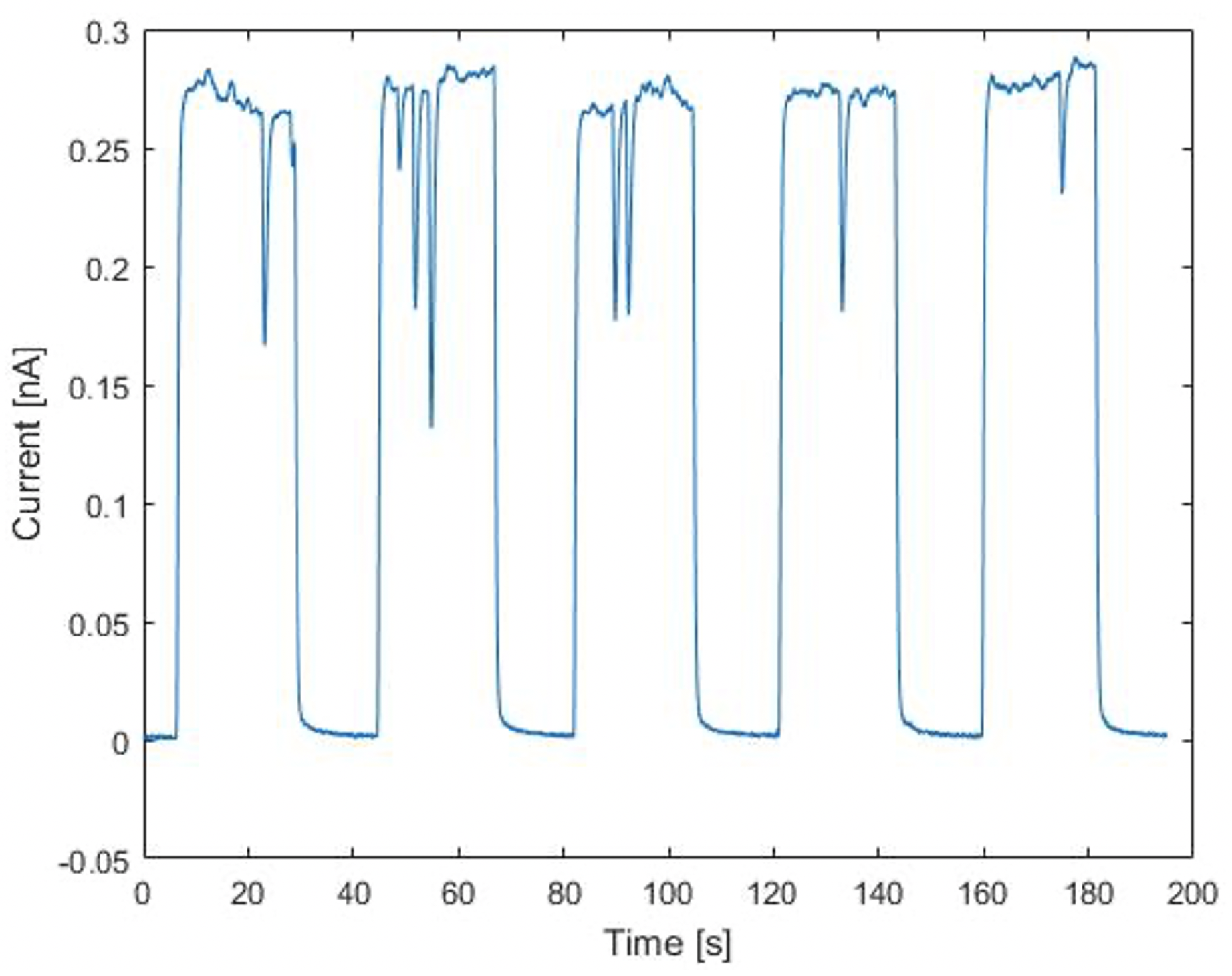
All the experimental measures involved recording the detector signals for five repeated irradiations corresponding with the same released dose. The integrated charge values and the corresponding uncertainties were estimated as the average and standard deviation of the five consecutive measurements, respectively. Figure 2 shows an example of the detector current output in the five irradiations. Each curve corresponds to a dose of 4 Gy, released at the water-tank entrance. The huge variations in the signals are due the proton beam instabilities during the irradiations and could be the cause of the lower observed sensitivity with respect to the calculations.

2.3. Set-Up for In Vivo Irradiation

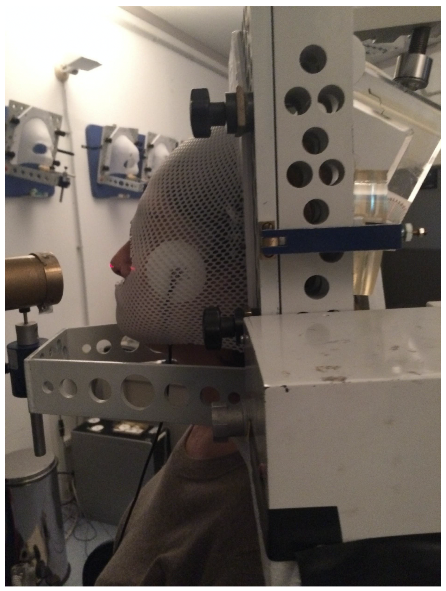
A set of preliminary in vivo tests were also performed on patients undergoing eye melanoma proton-therapy treatments. During the irradiation, the patients were positioned upon an electrically isolated chair and the electrode located on the patient’s skin, below the thermoplastic mask, close to the temporal region but outside the proton irradiation field (see Figure 3). The whole electronic chain and acquisition system were identical to those used in the in-phantom measurements.
During irradiations, both for the in-phantom and in-patient irradiations, the beam current was also monitored by a SEM (Secondary Emission Monitor) detector. It was positioned in vacuum, just before the beam exit window, at about three meters before the water-tank windows. The SEM is a monitoring system, providing a relative measure of the proton beam fluence. The SEM response is independent from the proton dose-rates [12,21] and was used as a beam reference.

3. Results and Discussion

The electrode dosimetric response was studied to investigate its response with respect to the dose released inside the water-tank and the proton beam dose rate. Short- and long-term stability, response dependence as a function of the proton beam field-size, position in the water-tank, and water temperature were also studied.

3.1. Dose and Dose-Rate Dependence

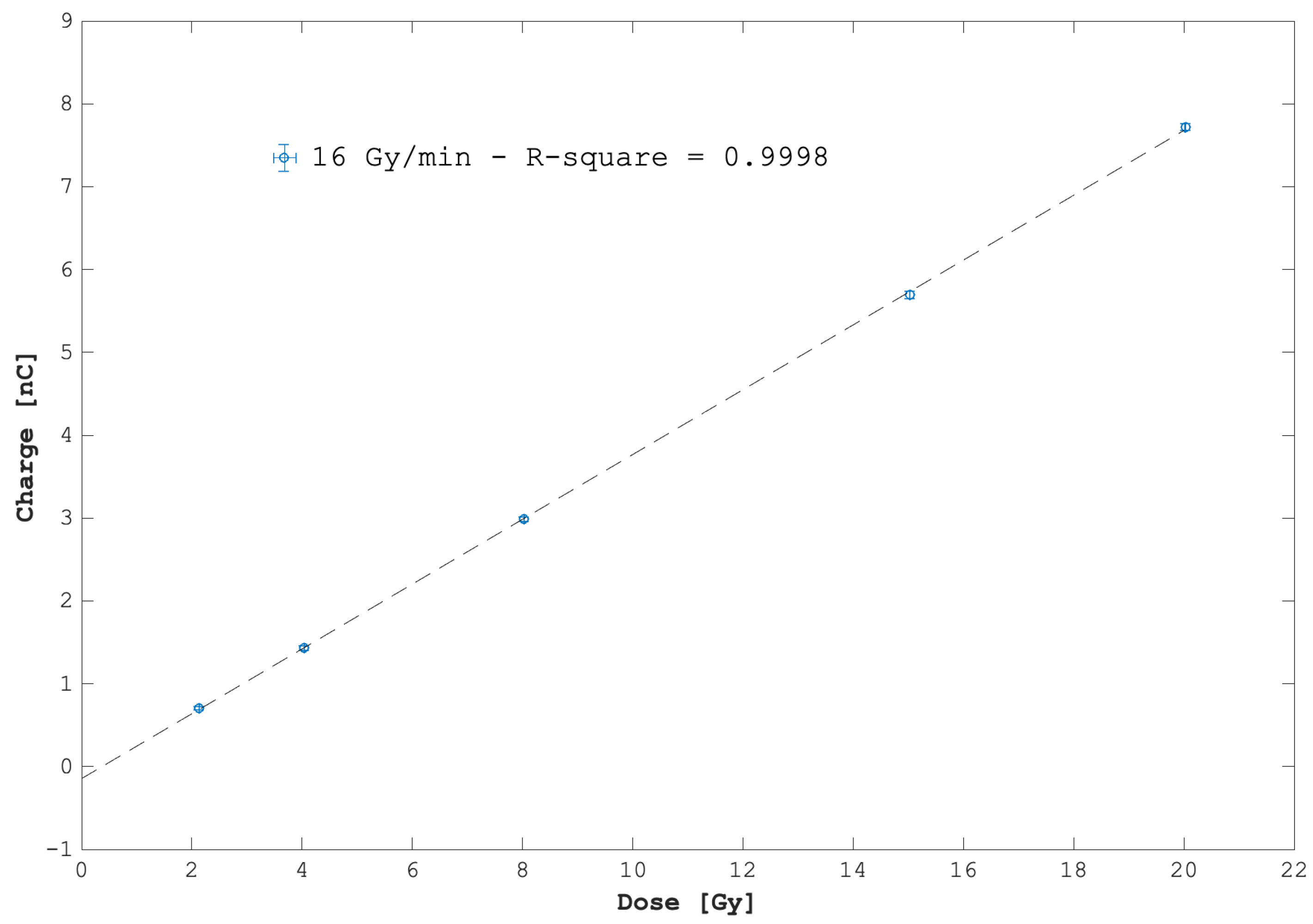
The detector response, as a function of the total dose released by the 62-MeV monochromatic proton beam, was studied in the 2–20 Gy range. The beam dose rate was kept fixed at 16 Gy/min. Considering that the variance associated to each point is not constant in the whole dose range, a weighted least square regression test was used to linearly fit data points. The fit result is reported in Figure 4. The detector response versus the released dose appears linear with an excellent confidence degree. A sensitivity of 0.3912 nC/Gy was derived from the measured data as the slope of the linear fit. Deviations no larger than ±2% were observed in the whole investigated dose range.
The detector sensitivity was also evaluated at six different values of dose-rate, in the range of 10–40 Gy/min. In Figure 5, the percentage discrepancy versus the charge collected at the maximum dose rate (39 Gy/min) is reported. A maximum variation of 3% was found.

3.2. Short-, Mid-, and Long-Term Reproducibility

Short-, mid-, and long-term reproducibility were investigated, and their values are summarized in Table 1. The proton beam dose-rate (16 Gy/min), dose (4 Gy), energy (60 MeV) at the irradiation point (i.e., at the detector position), and a circular beam spot 25 mm in diameter were taken as constants for all the measures.
The short-term reproducibility was investigated, evaluating the detector response in ten repeated irradiations of 4 Gy, then repeated five times within one hour. For each set of the ten measures, the averaged detector sensitivity, expressed in nC/Gy—i.e., as the ratio between measured charge and the corespondent released dose—was calculated. The maximum observed variation in the sensitivity was found to be less than 2% during the whole hour.
Similarly, the mid-term reproducibility was evaluated estimating the detector sensitivity ten times in five consecutive days. The maximum percentage difference observed was about 2.3%. For the long-term reproducibility, the sensitivity was measured ten times within 17 months, using the same irradiation conditions. In this case, the maximum percentage difference was 4.3%.

3.3. Current Monitoring Capabilities

Consider again the five current signals reported in Figure 2. Each curve corresponds to a nominal dose D n o m of 4 Gy released at the entrance of the water-tank. Integrating the current of each signal, we calculated the charge per dose unit (sensitivity) and measured an average value of <Q e x p /D n o m > = 0.367 nC/Gy and a standard deviation of 0.005 nC/Gy.
The expected theoretical sensitivity Q T h /D n o m was calculated from the expression (1):
Q T h D n o m = N p · q e D n o m = S · q e ( d E d x ) 60 MeV
where S is the beam spot surface at isocenter (S = 5.31 ± 0.21 cm 2 ); d E d x 60 MeV is the 60-MeV (energy at the isocenter point) proton massive stopping power in water (10.78 ± 0.01 MeV·cm 2 /g); D n o m is the nominal absorbed dose in water at the entrance of the water phantom; N p is the total number of the incident protons; q e is the elementary charge unit.
A value of Q T h /D n o m = 0.393 ± 0.020 nC/Gy was found, deviating 6.6% from the experimental <Q e x p /D n o m > result. This demonstrated the ability of the developed system to estimate the total charge received and, hence, of the dose absorbed at the entrance of the water tank. We quantitatively analyzed the SEM and Electrode signals, comparing their main characteristics: signal rise- and fall-time (defined as the time intervals needed to the signal for raising from 10% to 90% and for falling from 90% to 10% of its maximum, respectively), Full Width at Half Maximum (FWHM), and the curve integrals of each signal. Results are summarized in Table 2.
Despite the rise-time differences, mainly due to the RC time constants of the Electrode front-end read-out circuit (see Section 2.1), the percentage difference between the FWHMs and total integrals was less than 0.02% and 0.4%, respectively.

3.4. Field-Size Dependence

For circular beams with an homogenous lateral distribution, as those used in the current work, a proportionality of the detector signal with the square of the beam radius is expected. In order to verify such a dependence, the collected charge was measured using irradiation fields of different diameters (5 mm, 10 mm, 15 mm, 20 mm, 25 mm, and 36 mm). A second-order polynomial fit was applied and an r 2 value equal to 0.9978 was obtained, confirming the expected behavior of the detector response.

3.5. Position and Temperature Dependence

The Electrode response as a function of its position with respect to the beam entrance and the water temperature was evaluated.
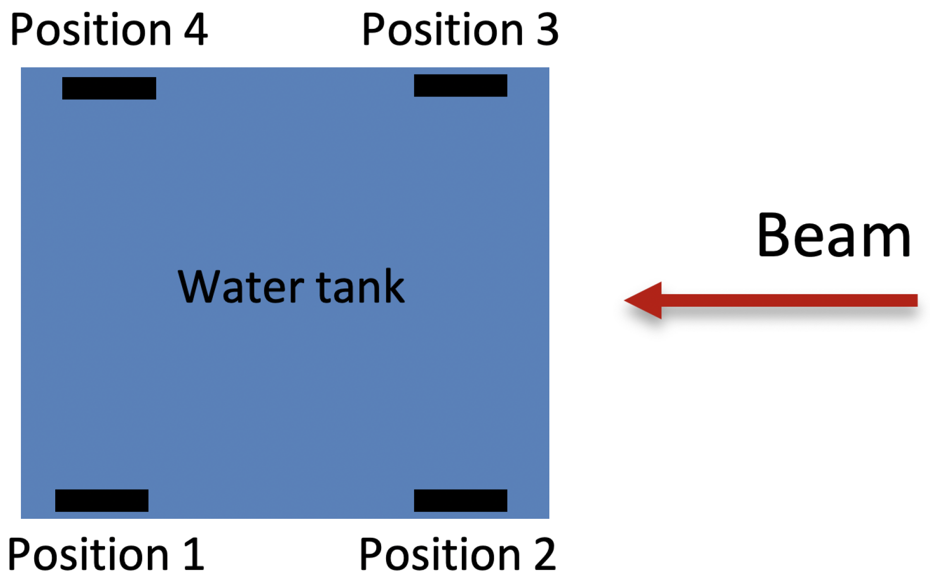
In order to study the position dependence, the detector was irradiated in four different positions, as shown in Figure 6 where a sketch of the water tank (view from the top) and the Electrode positions are presented. In each position, ten consecutive irradiations, corresponding to a released dose of 4 Gy at the entrance position of the water tank, were performed. A maximum percentage difference of 5.3% was found for the detector response in the four positions.
The detector dependence with respect to the temperature was investigated in the temperature range of 20–40 °C. Differences lower than 3% between the lowest and highest values were observed.

4. Preliminary In Vivo Tests

Some in vivo tests were performed on one patient undergoing eye proton-therapy irradiations at the CATANA facility [19,20,21].
In each irradiation session (of the four required by the clinical protocols), the patient received a dose of 15-Gy Cobalt-equivalent, released with a clinical Spread Out Bragg Peak obtained from a 62-MeV proton beam and a plastic modulator. The proton beam field was tailored on the tumor shape by means of a brass collimator designed by the treatment planning system [21]. In Table 3, the treatment duration, the collected charge, and the nominal delivered dose in each of the four sessions are reported.
The average charge measured in the four sessions was 3.25 ± 0.10 nC; the small percentage error (around 3%) demonstrates the good repeatability of the detector response in the case of patient irradiations.
Figure 7, finally, demonstrates how the system can be successfully used to monitor the beam current during treatment. It shows the detector response corresponding to the treatment session number 3 of Table 3. Around the second 85, the beam (orange dots) suddenly stopped for some technical reasons, restarting around the second 90. At the same time, the detector signal (black dots) dropped off, indicating the beam stop and the missing irradiation.

5. Conclusions and Perspectives

The suitability of a new online, noninvasive, biasless detector for relative dose monitoring in patients undergoing charged particle radiotherapy treatments was investigated. The device, a floating electrode connected on the patient’s skin, collects the charge delivered by the beam and returns a current signal proportional to the total charge deposited by the beam. The system was firstly characterized in vitro, irradiated inside a dosimetric water-tank with a clinical monochromatic 60 MeV proton beam. Short-, mid-, and long-term reproducibilities were studied and their values resulted better than 4.3%. The system resulted was independent from the temperature (5% maximum difference in the 20–40 °C range) and its response was proportional to the irradiation field area with a good confidence degree (R2 = 0.9978). The characterization evidenced a very good linearity with the dose absorbed in the water tank, in the 2–20 Gy range, with R 2 = 0.9999 and a deviation from linearity of less than 2%.
The device’s response was also independent from the proton beam dose rate in the 10–40 Gy/min range, where a maximum percentage difference of 3% was found.
Preliminary in vivo tests highlighted the capability of the device in acting as beam monitoring during a patient proton-therapy treatment and its ability in the verification of the correct dose delivered among the various fractions of the treatment. The set of performed tests, even if preliminary, show the capability of the system in operating as a beam monitoring device. The acquired results appear statistically robust, where no standard deviation bigger of 4.3% was observed in the sets of the repeated measures. On the other way, the system characterization must be completed, including additional tests. For example, the system response with respect to different beams’ energies must be studied in order to exclude (or determine) potential dependencies with the proton linear energy transfer (or LET). Additionally, materials other then water but similar to biological tissue composition must be investigated. The in vivo characterization, that obviously suffers from a lack of sufficient data, must be repeated with several more measures in order to reach a good statistical significance.
Improvement of the Electrode read-out circuits are ongoing to minimize the current leakage during in vivo irradiations. Its characterization under electrons and carbon ion beams is under way as well.

6. Patents

The device described in this work is protected by both a National Italian (N. 102017000087851) and an International N. WO 2019/025933 patent.

Author Contributions

The Idea of this device is from G.A.P.C., design and experimental implementation was performed by G.A.P.C. and G.P. (Giada Petringa); the low-noise, front-end electronic was developed by N.A. and A.M.; the clinical implementation was organized and followed by L.R., V.S., C.S. and G.C.; experimental sessions were organized and led by G.A.P.C., G.P. (Giada Petringa), and R.C.; data analysis and data interpretation were performed by G.A.P.C., G.P. (Giada Petringa) and P.L. A.D.D. F.P. and G.P. (Giuseppe Pittà) have realized a research prototype in industrial perspective. All authors have read and agreed to the published version of the manuscript.

Funding

This research was funded by the Tecnology Transfer Committee of the Istituto Nazionale di Fisica Nucleare (INFN) in the framework of the ELECTRODE project (2017–2018). The realization of the device was also supported by the DE.TEC.TOR. Company and by the Committee for the Interdisciplinari Researches of INFN.

Institutional Review Board Statement

This study was conducted irradiating one patient that personally signed an informed consent.

Informed Consent Statement

Informed consent was obtained from all subjects involved in the study.

Data Availability Statement

Data are not publicly available.

Conflicts of Interest

The authors declare that this device is protected by a national and International patent and that it could be commercialized in the future. At the moment of writing the described device is not commercialized and no conflict of interest is present.

References

  1. Olaciregui-Ruiz, I.; Beddar, S.; Greer, P.; Jornet, N.; McCurdy, B.; Paiva-Fonseca, G.; Mijnheer, B.; Verhaegen, F. In vivo dosimetry in external beam photon radiotherapy: Requirements and future directions for research, development, and clinical practice. Phys. Imaging Radiat. Oncol. 2020, 15, 108–116. [Google Scholar] [CrossRef] [PubMed]
  2. Mijnheer, B.; Beddar, B.; Izewska, J.; Reft, C. In vivo dosimetry in external beam radiotherapy. Med. Phys. 2013, 40, 070903. [Google Scholar] [CrossRef] [PubMed]
  3. Bourhis, J.; Jeanneret Sozzi, W.; Gonçalves Jorge, P.; Gaide, O.; Bailat, C.; Duclos, F.; Patin, D.; Ozsahin, M.; Bochud, F.; Germond, J.; et al. Treatment of a first patient with FLASH-radiotherapy. Radiother. Oncol. 2019, 139, 18–22. [Google Scholar] [CrossRef] [PubMed]
  4. Gonçalves Jorge, P.; Jaccard, M.; Petersson, K.; Gondré, M.; Durán, M.T.; Desorgher, L.; Germond, J.F.; Liger, P.; Vozenin, M.C.; Bourhis, J.; et al. Dosimetric and preparation procedures for irradiating biological models with pulsed electron beam at ultra-high dose-rate. Radiother. Oncol. 2019, 139, 34–60. [Google Scholar] [CrossRef] [PubMed]
  5. Schüler, E.; Trovati, S.; King, G.; Lartey, F.; Rafat, M.; Villegas, M.; Maxim, P.G. Experimental platform for ultra-high dose rate FLASH irradiation of small animals using a clinical linear accelerator. Int. J. Radiat. Oncol. Biol. Phys. 2017, 97, 195–203. [Google Scholar] [CrossRef]
  6. Kortov, V. Materials for thermoluminescent dosimetry: Current status and future trends. Radiat. Meas. 2007, 42, 576–581. [Google Scholar] [CrossRef]
  7. Niroomand-Rad, A.; Blackwell, C.R.; Coursey, B.M.; Gall, K.P. Radiochromic film dosimetry: Recommendations of AAPM Radiation Therapy Committee Task Group 55. Med. Phys. 1998, 25, 2093–2115. [Google Scholar] [CrossRef] [PubMed] [Green Version]
  8. Oliveira, F.F.; Amaral, L.L.; Costa, A.M.; Netto, T.G. In vivo dosimetry with silicon diodes in total body irradiation. Radiat. Phys. Chem. 2014, 95, 230–232. [Google Scholar] [CrossRef]
  9. Dixon, R.L.; Ekstrand, K.E. Silicon diode dosimetry. Int. J. Appl. Radiat. Isot. 1982, 33, 1171–1176. [Google Scholar] [CrossRef]
  10. Diode In-Vivo Dosimetry for Patient Receiving External Beam Radiation Therapy; Report of Task Group 62 of the Radiation Therapy Committee Published for the American Association of Physicists in Medicine by Medical Physics Publishing; AAPM Report No. 87; American Association of Physicists in Medicine: Alexandria, VA, USA, 2005.
  11. Ravichandran, R.; Binukumar, J.P.; Al Amri, I. Diamond detector in absorbed dose measurements in high-energy linear accelerator photon and electron beams. J. Appl. Clin. Med. Phys. 2016, 2, 291–303. [Google Scholar] [CrossRef] [PubMed] [Green Version]
  12. Cirrone, G.A.P.; Cuttone, G.; Rafaele, L.; Sabini, M.G.; De Angelis, C.; Onori, S.; Pacilio, M.; Bucciolini, M.; Bruzzi, M. Natural and CVD type diamond detectors as dosimeters in hadrontherapy applications. Nucl. Phys. B Proc. Supp. 2003, 125, 179–183. [Google Scholar] [CrossRef]
  13. Bucciolini, M.; Banci Buonamici, F.; Mazzocchi, S.; De Angelis, C.; Onori, S.; Cirrone, G.A.P. Diamond detector versus silicon diode and ion chamber in photon beams of different energy and field size. Med. Phys. 2003, 30, 2149–2154. [Google Scholar] [CrossRef] [PubMed]
  14. Manigandan, D.; Bharanidharan, G.; Aruna, P.; Devan, K.; Elangovan, D.; Patil, V.; Tamilarasan, R.; Vasanthan, S.; Ganesan, S. Dosimetric characteristics of a MOSFET dosimeter for clinical electron beams. Phys. Medica 2009, 25, 141–147. [Google Scholar] [CrossRef] [PubMed]
  15. Cirrone, G.A.P.; Cuttone, G.; Lojacono, P.A.; Lo Nigro, S.; Patti, V.I.; Pittera, S.; Raffaele, L.; Sabini, M.G.; Salamone, V.; Valastro, L.M. Preliminary investigation on the use of the MOSFET dosimeter in proton beams. Physica Medica 2006, 22, 29–32. [Google Scholar] [CrossRef]
  16. Development of Procedures for In Vivo Dosimetry in Radiotherapy; Technical Report Series No. 8; International Atomic Energy Agency: Wien, Austria, 2013.
  17. Di Venanzio, C.; Marinelli, M.; Milani, E. Characterization of synthetic single crystal diamond Schottky diode for radiotherapy electron beam dosimetry. Med. Phys. 2013, 40, 021712. [Google Scholar] [CrossRef] [PubMed] [Green Version]
  18. Alnawaf, H.; Butson, M.; Yu, P.K.N. Measurement and effects of MOSKIN detectors on skin dose during high energy radiotherapy treatment. Australas. Phys. Eng. Sci. Med. 2012, 35, 321–328. [Google Scholar] [CrossRef] [PubMed]
  19. Cirrone, G.A.P.; Cuttone, G.; Lojacono, P.A.; Nigro, S.L.; Mongelli, V.; Patti, I.V.; Privitera, G.; Raffaele, L.; Rifuggiato, D.; Sabini, M.G.; et al. A 62-MeV proton beam for the treatment of ocular melanoma at Laboratori Nazionali del Sud-INFN. IEEE Trans. Nucl. Sci. 2004, 51, 860–865. [Google Scholar] [CrossRef]
  20. Cuttone, G.; Cirrone, G.A.P.; Di Franco, G.; La Monaca, V.; Lo Nigro, S.; Ott, J.; Pittera, S.; Privitera, G.; Raffaele, L.; Reibaldi, A.; et al. CATANA protontherapy facility: The state of art of clinical and dosimetric experience. Eur. Phys. J. Plus 2011, 126, 65. [Google Scholar] [CrossRef]
  21. Cirrone, G.A.P.; Cuttone, G.; Raffele, L.; Salamone, V.; Avitabile, T.; Privitera, G.; Corrado, S.; Amico, A.; La Rosa, G.; Leanza, R.; et al. Clinical and Research Activities at the CATANA Facility of INFN-LNS: From the Conventional Hadrontherapy to the Laser-Driven Approach. Front. Oncol. 2017, 7, 223. [Google Scholar] [CrossRef] [PubMed] [Green Version]
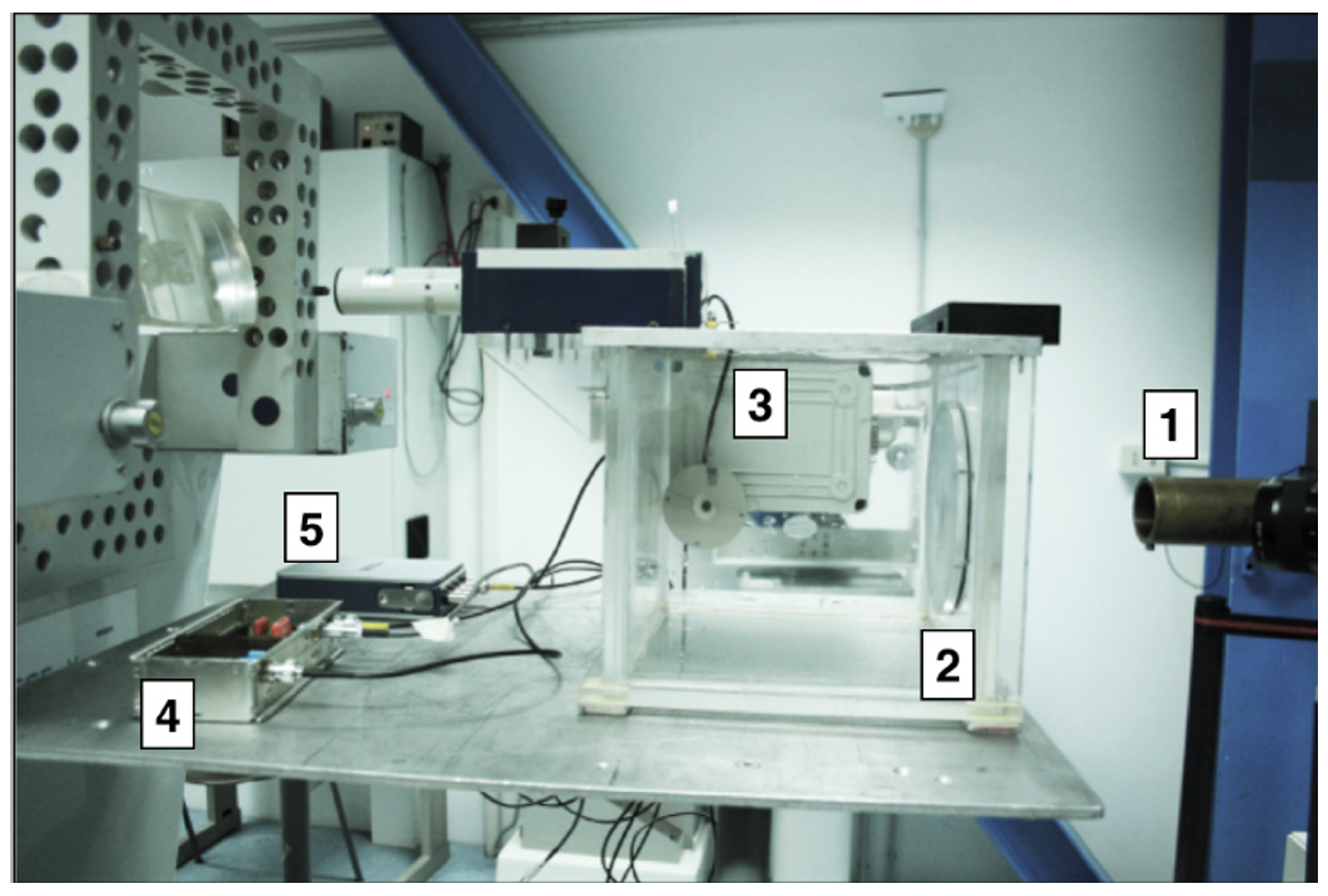
Figure 1. Experimental set-up adopted for the experimental measurements: (1) circular, 25 mm in diameter, brass collimator; (2) the water tank; (3) the electrode, positioned inside its holder and immersed in water outside the proton field; (4) the transimpedance amplifier; (5) the NI 9223 digital scope.
Applsci 11 07005 g001
Figure 2. Detector current output for five consecutive proton irradiations. Each positive signal corresponds to a nominal dose of 4 Gy released at the water-tank entrance.
Applsci 11 07005 g002
Figure 3. A patient just before the proton therapy session with the electrode system positioned under the thermoplastic mask.
Applsci 11 07005 g003
Figure 4. Detector response as a function of the released dose in water. The linear fit shows an excellent confidence degree expressed by the R2 parameter.
Applsci 11 07005 g004
Figure 5. Percentage variations, with respect to the value measured at the maximum dose rate (39 Gy/min) of the collected charge for growing values of beam dose—rate.
Applsci 11 07005 g005
Figure 6. Four different irradiation configurations, each for one electrode position in the water phantom (view from the top).
Applsci 11 07005 g006
Figure 7. Proton beam signal (orange dots) measured by secondary electron monitoring (SEM) and the corresponding signal acquired by the electrode (black dots) positioned on the patient’s skin (see Figure 3). It is interesting to note that the sudden and unexpected beam stop during irradiation (at around second 85) and its next recovery (at around second 90) is perfectly followed by the electrode signal.
Applsci 11 07005 g007
Table 1. Short-, mid-, and long-term reproducibility expressed as percentage variations of the detector sensitivities for the whole set of measurements.
Short-term reproducibility≤2%
Mid-term reproducibility≤2.3%
Long-term reproducibility≤4.3%
Table 2. Comparisons of the main parameters of the curves reported in Figure 2.
Rise Time (s)Fall Time (s)FWHM (s)Charge Integral (nC)
SEM0.43 ± 0.020.37 ± 0.0252.03 ± 0.0249.32 ± 0.01
ELECTRODE0.80 ± 0.020.65 ± 0.0252.03 ± 0.0249.50 ± 0.01
Difference [%]46430.020.36
Table 3. Irradiation parameters and results obtained during the patient irradiation session.
SessionTime (s)Charge (nC)Nominal Dose (cGy)
1403.32 ± 0.061366
2423.14 ± 0.061366
3353.19 ± 0.061366
4443.35 ± 0.061366
Publisher’s Note: MDPI stays neutral with regard to jurisdictional claims in published maps and institutional affiliations.