Article

Dielectrophoretic Manipulation of Cell Transfection Efficiency during Electroporation Using a Center Needle Electrode

by
Eivina Radzevičiūtė
1,
Arūnas Murauskas
2,
Paulius Ruzgys
3,
Saulius Šatkauskas
3,
Irutė Girkontaitė
1,
Jurij Novickij
2 and
Vitalij Novickij
2,*
1
Department of Immunology, State Research Institute Centre for Innovative Medicine, 08406 Vilnius, Lithuania
2
Faculty of Electronics, Vilnius Gediminas Technical University, 08412 Vilnius, Lithuania
3
Biophysics Group, Vytautas Magnus University, 44248 Kaunas, Lithuania
*
Author to whom correspondence should be addressed.
Appl. Sci. 2021, 11(15), 7015; https://doi.org/10.3390/app11157015
Submission received: 25 May 2021 / Revised: 2 July 2021 / Accepted: 28 July 2021 / Published: 29 July 2021
(This article belongs to the Special Issue Electroporation Systems and Applications)

Abstract

:
Long duration electric pulses are frequently used to facilitate DNA electrotransfer into cells and tissues, while electroporation pulses can be combined with electrophoresis to maximize the transfection efficiency. In this work, we present the dielectrophoresis (DEP)-assisted methodology for electrotransfer of plasmid DNA (3.5 kbp pmaxGFP) into mammalian cells (CHO-K1). A prototype of an electroporation cuvette with center needle electrode for DEP-assisted transfection is presented resulting in a 1.4-fold of transfection efficiency increase compared to the electroporation-only procedure (1.4 kV/cm × 100 µs × 8). The efficiency of transfection has been compared between three DEP frequencies of 1, 100, and 1 MHz. Lastly, the effects of exposure time (1, 3, and 5 min) during the DEP application step have been determined. It is concluded that the proposed methodology and exposure setup allow a significant improvement of transfection efficiency and could be used as an alternative to the currently popular electrotransfection techniques.

1. Introduction

Non-viral DNA delivery systems can involve electroporation (EP), which is a pulsed power technique based on the application of pulsed electric field (PEF) to trigger increased permeabilization of cell membrane [1,2]. It is a physical process depending on the cell type and pulse parameters, however, when tuned right, it enables controlled cellular uptake of exogenous materials [3]. In the case of plasmid DNA transfer, the EP protocols typically employ long micro or even millisecond range pulses [4,5].
Partly, the positive effect of longer pulses is due to the electrophoretic component [6,7], which is more significant with the increase of pulse duration. As a side effect, long high voltage pulses are accompanied with electrochemical reactions in the vicinity of the electrodes [8], thus generation of reactive oxygen species (ROS) [9], pH fronts [10], and possible DNA denaturation can occur [11]. Finally, the long duration of the pulse (when increased inappropriately) may result in loss of cell viability [12]. In order to overcome the problems and exploit the significant positive effects of electrophoresis, a separate electrotranfection methodology called the HV/LV pulsing was developed [13,14]. A combination of short “cell permeabilizing” high voltage (HV) pulses with long (ms range) “electrophoretic” but low voltage (LV) pulses, results in a significant improvement of transfection efficiency [13,15]. Nevertheless, in pursuit to improve the transfection efficiency even further, a study of other pulse parameters and various combinations is constantly performed.
A successful effort to combine nanosecond pulsed electric fields (nsPEFs) with long pulses has been reported [16]. It was shown that the pretreatment but not posttreatment with nsPEFs was critical to significantly influence the gene expression [16]. However, when other cell lines and nanosecond pulse parameters were used, nsPEFs had no major contribution to the gene electrotransfer even when combined with longer pulses [17]. Later, Salomone et al. have used endosomolytic peptide, CM18-Tat11 to facilitate transfection using nanosecond pulses, which showed positive results [18]. Recently, we have also shown that high frequency sub-microsecond range protocols, which are equivalent (efficiency-wise) to microsecond range procedures can be derived using MHz pulsing sequencies [19]. However, as a drawback, such protocols require state-of-art electroporators for pulse delivery, thus further optimization of the methodology is performed and trade-offs are expected.
Another polarization-based technology, which enables spatial manipulation of cells and molecules is dielectrophoresis. Dielectrophoresis (DEP) is a phenomenon of a motion of a polar or polarizable particle, e.g., a biological cell when subjected to a non-uniform electric field [20]. Electroporation is common to be combined with DEP. In the context of cell fusion, DEP is used to increase the cell density and thus, improve the efficacy of electrofusion [21]. DEP can be also successfully applied for transfection. A dielectrophoretically-assisted electroporation platform was proposed by Wang et al. [22]. Punjiya et al. presented a flow through device for simultaneous dielectrophoretic cell trapping and AC electroporation [23]. The idea of DEP-assisted electrotransfection was extensively covered by others, as well. However, mostly using DEP entrapment and microfluidic systems [24]. One of the main reasons is the DEP force scaling with electrode dimensions.
The DEP force is defined as [25]:
F = (m∇)E
where ∇ is the gradient of the electric field E and the particle dipole moment m is equal to:
m = pυE
where υ is the volume and p is the effective polarizability of the particle, generally referred to as the Clausius-Mosotti factor [26]. From Equations (2) and (3), the translational (DEP) force can be re-written as:
F = pυ(E∇)Epυ∇|E|2
which implies that if the field is uniform (∇E = 0), the DEP force is also equal to 0. Therefore, no DEP can be induced in a commercial parallel plate electrode cuvette, when the field is mostly homogeneous. Therefore, classical DEP devices are limited by restrictions on the micro-channels to achieve large enough electric field gradients [27]. Therefore, the DEP force can be manipulated by the polarizability of the cell, effect volume, square of the applied electric field magnitude, and the geometry of electrodes, but only the last two parameters can be effectively changed to produce a non-uniform electric field for sufficient DEP force affecting electrotransfer. All factors combined, it is still challenging to present a reusable high-throughput device when the effective volume is limited and there are risks of clogging the channel.
Therefore, in this work, we decided to integrate a center needle electrode into a commercial electroporation cuvette to form a simple, reusable electrotransfection chamber. The aim of the study is to show the applicability of non-micro scale DEP and to develop protocols complexity-wise as simples as the current electrotransfection procedures. The schematic representation of the setup and treatment methodology is shown in Figure 1.
We decided to employ conventional square-wave electroporation using protocols similar to European Standard Operating Procedures for Electrochemotherapy (ESOPE), which are also popular in electrotransfection. Therefore, in this study, they were used as a reference. Furthermore, the conventional EP was accompanied by DEP, which was induced in the cuvette before and after EP. The needle electrode was introduced to generate an electric field gradient required for DEP. Finally, we have employed square-wave DEP, which due to the waveform involves high frequency harmonics. It is beneficial for our study, since the RMS value of square wave pulses (when compared to sine of the same frequency) is √2 times higher. Previously, Contreras-Dávila et al. have shown that the application of square wave more than doubles the DEP entrapment capability compared to the sine [28]. As a result, the lower peak-to-peak voltage can be used to trigger equivalent effects [28,29]. It is beneficial in the electrotransfection context, since the high electric field region can be reduced near the center electrode to prevent electroporation.

2. Materials and Methods

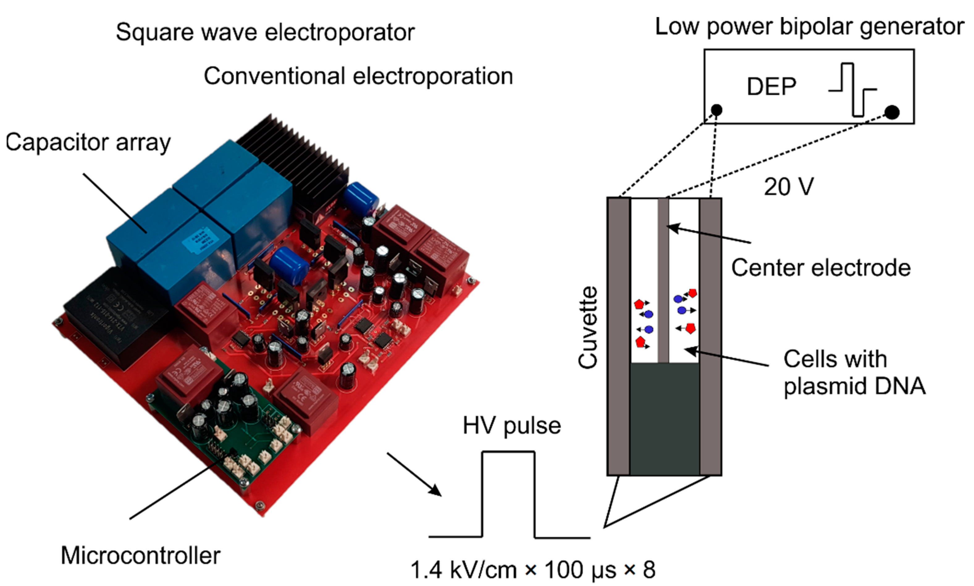
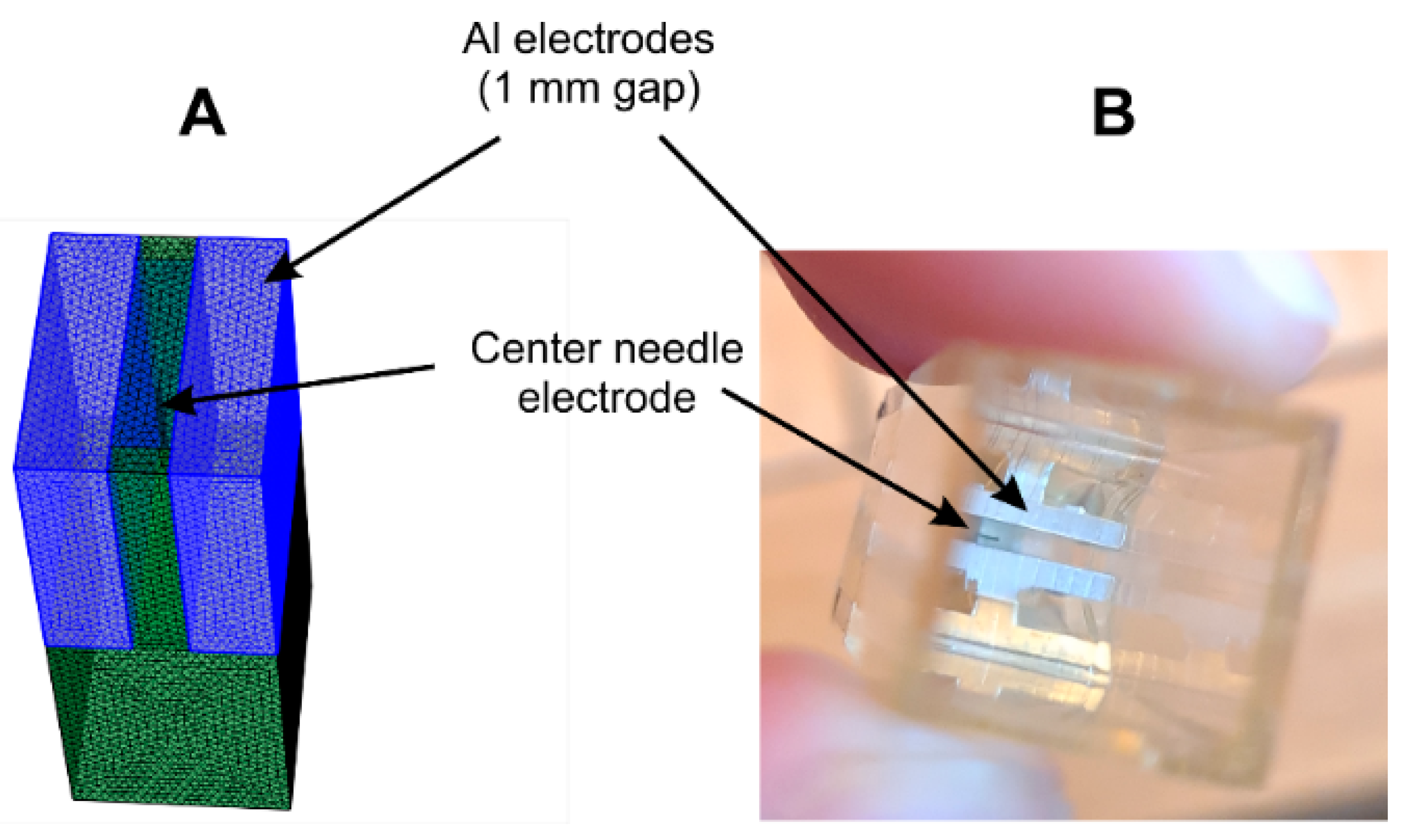
2.1. Dielectrophoresis-Assited Electroporation Setup

The square wave high voltage pulse generator was used for electroporation [30]. A commercially available electroporation cuvette with 1 mm gap aluminum electrodes (Biorad, Hercules, CA, USA) was used as a load. As a protocol, a 1.4 kV/cm × 100 µs × 8 pulse sequence was delivered at 1 Hz (PEF only). A 0.1 mm diameter needle stainless steel electrode has been integrated in the center of the cuvette for DEP induction and driven by the alternating current square 20 Vpp (peak-to-peak) wave. The treatment times included 1, 3, and 5 min DEP protocols. Four pulse protocols were compared: (1) PEF only; (2) DEP only; (3) PEF + DEP; and (4) DEP + PEF to cover all the possible combinations. Moreover, DEP is a frequency dependent phenomenon, therefore, three frequencies have been chosen in this study: DEP1: 1 kHz, DEP2: 100 kHz, and DEP3: 1 MHz, to account for the changes in the Clausius-Mossotti factor [31].

2.2. Preparation of Cells

Chinese Hamster Ovary cells CHO-K1 were maintained in RPMI 1640 medium supplemented with 2 mM glutamine, 100 U/mL penicillin, 100 mg/mL streptomycin, and 10% of fetal calf serum (FCS). The CHO-K1 cells were acquired from American Type Culture Collection (ATCC, Manassas, VA, USA). All applicable international, national and/or institutional ethical guidelines were followed. All of the cell culture reagents were obtained from Gibco, Thermo Fisher Scientific, Waltham, MA, USA. The cells were cultured at 37 °C, 5% CO2. The day before electroporation the cells were plated into 6-well tissue culture plates 0.3 × 10⁶ cells per well. The next morning the cells were trypsinized, centrifuged, and resuspended in the buffer for electroporation (242 mM saccharose, 5.5 mM Na2HPO4, 3 mM NaHPO4, 1.7 mM MgCl2, pH 7.1) at concentration 6 × 10⁶/mL and incubated on ice before the pulse treatment.

2.3. Transfection of Cells

Samples (27 µL) of ice-cold cell suspension and 3 µL of plasmid DNA (2 mg/mL in H2O, purified with HiPure Expi Plasmid Gigaprep Kit (Thermo Fisher Scientific, Waltham, MA, USA) were mixed in 1.5 mL tube (Eppendorf, Hamburg, Germany) and transferred into an electroporation cuvette with 1 mm gap aluminum electrodes (Biorad, Hercules, CA, USA). The efficiency of transfection was evaluated using 3.5 kbp (pmaxGFP) plasmid. After electroporation or the combination with DEP treatment the cells were transferred into a 48-well plate and incubated on ice for 10 min, followed by 0.5 mL addition of the cell culture media. Afterwards, the cells were kept for 24 h at 37 °C, 5% CO2.
The next day the cells were again trypsinized, centrifuged at 200× g, and resuspended in 100 µL of PBS. Then, the transfected (GFP positive cells) were evaluated using a flow cytometer (BD Accuri C6, BD Biosciences, Franklin Lakes, NJ, USA). For discrimination of dead/apoptotic cells, the samples were additionally stained with 7-amino-actinomycin D (7-AAD) (BDPharmingen, Boston, MA, USA).

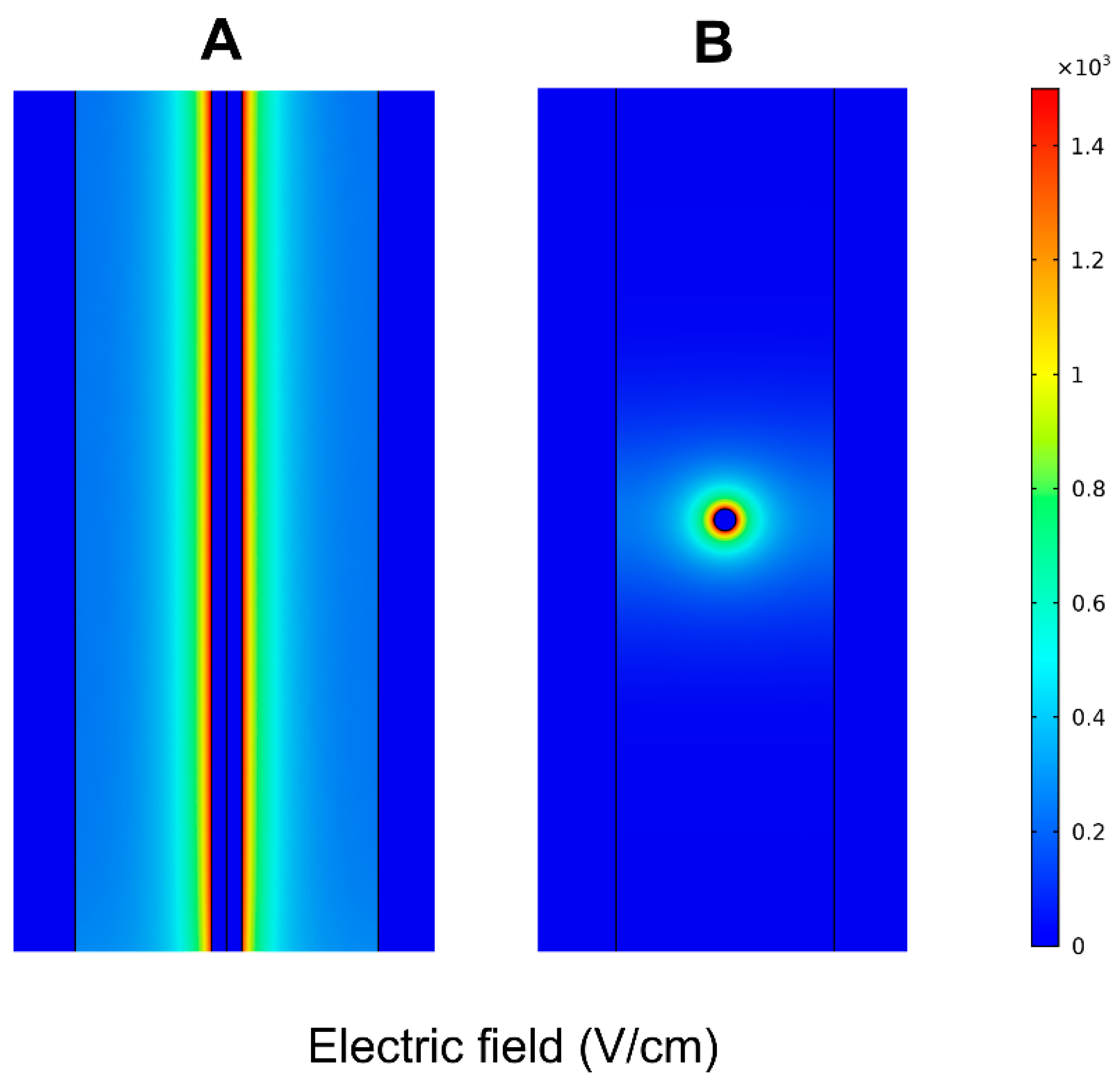
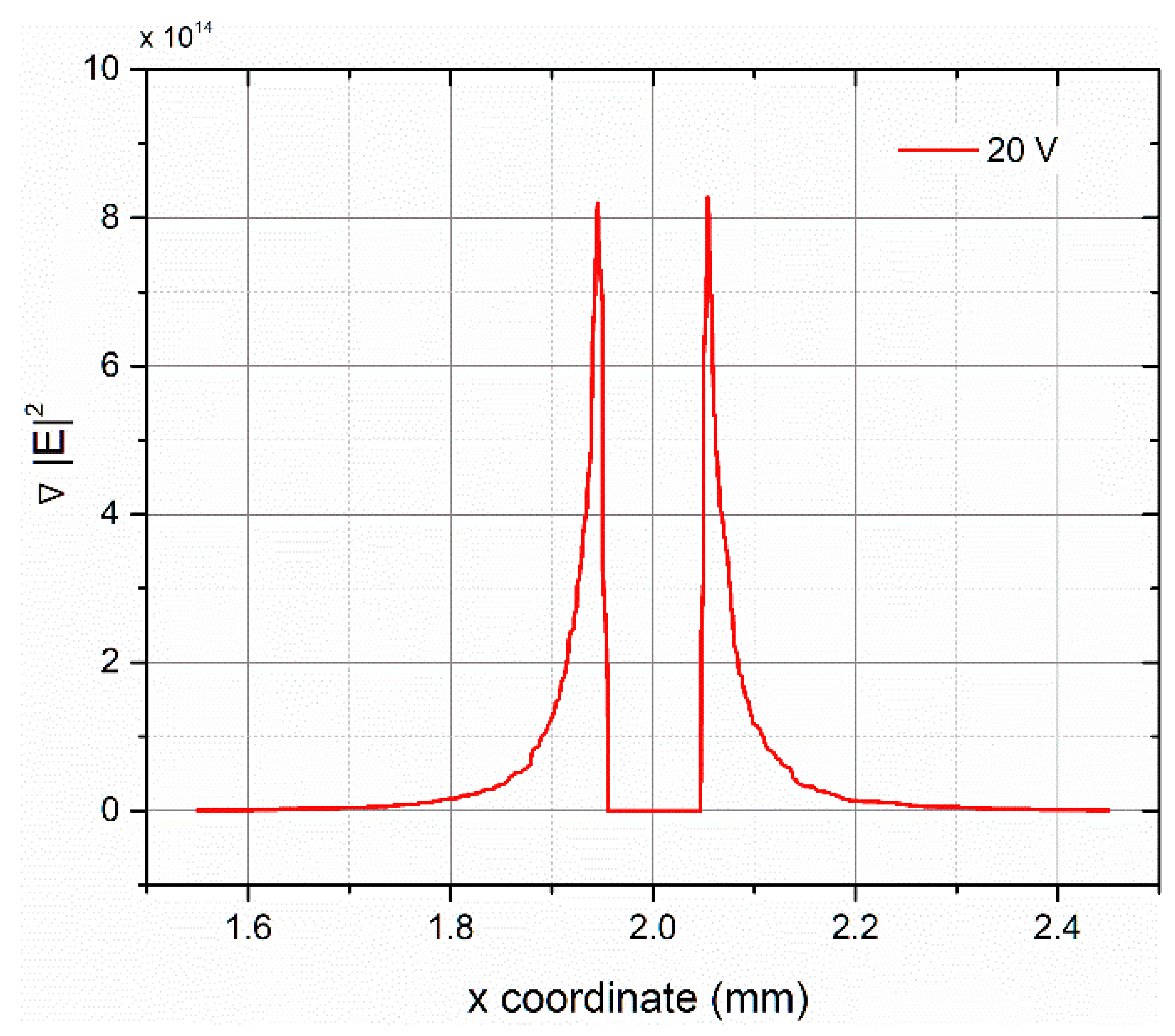
2.4. Finite Element Method Analysis

In order to estimate the electric field gradient and resultant electric field amplitude during application of the DEP pulses, the finite element method (FEM) model of the proposed cuvette design was developed in COMSOL (Comsol Multiphysics, Stockholm, Sweden). The parameters of the model are summarized in Table 1.
A 3D simulation model was introduced and an extremely fine mesh was used with minimal and maximal element size ranging from 0.002 to 0.2 mm, respectively. The maximum element growth rate of 1.3 was selected and the curvature factor of 0.2. The resultant mesh and the actual prototype of the cuvette are shown in Figure 2.
The stationary electric currents (EC) physics module was used, where the parallel plate aluminum electrodes were selected as ground electrodes, while the 20 V potential was applied to the center needle electrode.

2.5. Statistical Analysis

For treatments comparison, the one-way analysis of variance (ANOVA; p < 0.05) was used. If ANOVA showed significant effects, multiple tests were applied to evaluate the difference Tukey HSD (p < 0.05 was considered significant). All of the experiments have been performed at least in triplicate.

3. Results

The application of a voltage potential across a distance induces an electric field inside the cuvette. In the case of DEP, it is advantageous to have an electric field as high as possible to induce the highest force. However, the electric field amplitude should be below the electroporation threshold to prevent any effects of DEP on permeabilization and/or viability of cells. Therefore, the FEM analysis was performed to characterize the possible effects of DEP pulsing sequence. The spatial distribution of electric field inside the cuvette when 20 V of potential is applied is shown in Figure 3.
It can be seen that the induced electric field is non-homogeneous. Most of the volume is subjected to the sub-threshold electric field (<0.6 kV/cm). The higher electric field is generated only in close proximity with the electrode.
In order to generate a significant DEP force, the gradient of electric field should be maximized. A value for the factor ∇|E|2 of around 1013 V2/m3 is required to produce a detectable DEP force [32]. The ∇|E|2 factor inside the proposed cuvette was estimated and the results are presented in Figure 4.
It can be seen that the peak value exceeds 8 × 10¹⁴, which should be sufficient to induce dielectrophoretic motion. The gradient can be further improved by the introduction of additional needle electrodes inside the cuvette.
However, within the scope of this paper, it was important to show the proof of concept and the capability to control transfection efficiency via DEP sequence in a traditional cuvette.
Finally, the proposed cuvette was tested experimentally in transfection experiments. The electroporation sequences were applied separately (without DEP) and with various parameters DEP. The results are summarized in Figure 5.
As it can be seen in Figure 5A, the PEF only treatment resulted in a 27% ± 5% transfection efficiency. The value was used as a reference for comparison of the DEP-assisted treatments and is marked as a dashed line in the graphs (PEF only). The DEP only independently on the frequency did not induce detectable transfection.
The combination of DEP sequences with electroporation showed significant effects on the treatment outcome. Depending on the order of application (PEF + DEP or DEP + PEF) the efficacy of the treatment was either improved or inhibited, e.g., when 1 MHz DEP3 sequence was applied after PEF, the number of transfected cells increased 1.4-fold (from 27% to 37%). If the same DEP3 sequence was applied before PEF, the treatment efficacy was inhibited 1.3-fold (from 27% to 20%). Similar tendencies were observed for 1 and 100 kHz sequences. During the PEF + DEP protocol, the frequency response was statistically significant (p < 0.05) between DEP1 and DEP3 (1 kHz and 1 MHz, respectively). When the DEP + PEF methodology was employed, the DEP2 and DEP3 (100 kHz and 1 MHz) sequences showed statistically significant differences versus each other.
Furthermore, the effects of exposure time during the DEP application step were studied and the results are summarized in Figure 5B. It can be seen that independently on the time of the exposure (1, 3 or 5 min) the differences between DEP-assisted protocols are not significant (p > 0.05) or lost within the standard deviation of experimental data. It implies that 1 min is sufficient to produce a saturated response.
Finally, considering that 1 MHz DEP (DEP3) is the highest intensity treatment (due to high repetition of pulses), the viability of the cells after PEF + DEP3 treatments was compared. The results normalized to the untreated control are summarized in Table 2.
It can be seen that the pulsed treatment resulted in almost 30% reduction of the cells viability compared to the untreated control. Nevertheless, the DEP component had no effect on the cell viability. In all of the cases (independently on the treatment time), the combination of PEF + DEP had no statistically significant (p < 0.05) differences versus PEF only treatment.

4. Discussion

In this work, we have investigated the feasibility of dielectrophoresis to be induced in a conventional electroporation cuvette and the possibilities to affect the efficiency of transfection as an alternative to the HV/LV methodology (which relies on electrophoresis). It was shown that depending on the order of application (PEF + DEP or DEP + PEF) the transfection efficiency can be either improved or inhibited, which is an excellent and anticipated result. Considering the positive results, the electric field gradient and spatial distribution can be further improved by the introduction of an additional array of needle electrodes in the cuvette. With an increase of the number of needle electrodes, the next step could be using the 2- or 5-mm gap cuvettes, which would increase the volume and potentially allow even large numbers of cells to be processed. Based on our study, it can be concluded that the field gradient factor ∇|E|2 of 1014 is sufficient to induce detectable changes in the electrotransfer of DNA. Increasing it further may improve the processing time, however, we speculate that it is unlikely to change the efficacy of the treatment (refer to Figure 5B), while improvement of the spatial E field distribution should be the priority. Moreover, within the framework of our study, the DEP force and spatial distribution of the cells inside the cuvette were not simulated. The reason behind this is the inability for experimental confirmation of such simulations in the mL range cuvette. After electroporation the parameters such as cell size, conductivity, and extracellular medium conductivity dynamically change due to the biophysics of the electropermeabilization process. It implies that the Clausius-Mossotti factor becomes unpredictable, i.e., the range of applicable values due to electroporation enable both pDEP and nDEP to be equally plausible. Therefore, in order to perform spatial cell simulation, a microfluidic chip has to be developed for tuning of the simulation parameters. In our study, DEP characterization was limited to the use of ∇|E|2, which is a common practice since it does not depend on cell radius or Clausius-Mossotti factor and thus, no significant approximations are required. Furthermore, we employed square wave DEP, which involves high frequency harmonics in the signal. The effect of the harmonics of a square waveform contributes to a generation of a stronger DEP force (due to the RMS value) and additional DEP forces at its corresponding frequencies [28]. The application of square waves is easier and cheaper in terms of engineering, it is also advantageous in the context of electroporation since many commercial bipolar electroporators can be easily adapted for DEP-assisted electrotransfection.
Moreover, we have used a low conductivity buffer (0.1 S/m) to perform the experiments. However, the polarizability factor or the real part of the Clausius-Mossotti factor will be altered in buffers of different conductivities. The reason to use a low conductivity buffer was to maximize the DEP forces index, which for CHO cells increase with the decrease of conductivity [31]. Salimi et al. have also shown that in mediums with conductivity close to 0.1 S/m the real part of Re [p] for CHO cells is positive with a peaking DEP force index in the frequency of 106–107 [31]. Our results in part support the data, i.e., during the PEF + DEP protocols the highest transfection efficiency was reached when (1 MHz) the DEP3 sequence was used. Considering the available knowledge [29,31], the application of square waves, low conductivity buffer, and DEP frequencies including MHz pulsing allows maximizing the DEP force. Such an approach increased the number of transfected cells 1.4-fold (when compared to PEF only), which is competitive even against the HV/LV methodology [14,33]. However, multi-parametric studies including the effects of buffer conductivity might be useful in the future, especially in the context of mesenchymal cells, which are sensitive to the buffer composition [34]. Further optimization is possible both electrode-wise and pulse parameter-wise.
The straightforward advantage of the DEP-assisted methodology over HV/LV pulsing is the lack of directional electrophoresis (due to bipolar pulse shape) and thus the electrochemical reactions in the vicinity of the electrodes should be significantly minimized. Therefore, DNA denaturation should be minimized too.
In our work, we have used an applicator with two different metals (steel and aluminum) forming an electrochemical cell, which we believe is a limitation of the applicator and might have a negative impact on the cells during longer incubation times. However, considering the stability of the negative controls and good repeatability of the transfection experiments, the electrochemical effects are negligible for the proposed protocols. Nevertheless, optimization of electrodes material is recommended for future studies if incubation times exceeding 20–30 min are expected.
One of the most interesting phenomena determined during the study was the reduction of the transfection efficiency when DEP was preceding PEF pulses. Such a phenomenon is non-occurrent during HV/LV pulsing. We speculate that the reason behind the phenomenon may lie in the differences of the cross-over frequencies/polarizability of the CHO cells and DNA in AC fields [35,36]. After PEF, the Clausius-Mossotti factor and cell radius change dramatically (due to electroporation). Therefore, PEF + DEP and DEP + PEF can deliver different experimental outcomes, which is the case in our work. In order to confirm this hypothesis, a microfluidic system should be developed, which is a matter of future work.
The electroendocytosis as a mechanism might have an effect of the treatment outcome, as well [37,38]. It is a phenomenon of the uptake of the macromolecules into cells, following exposure to pulsed low electric fields, which does not involve an electric breakdown of the membrane (electroporation) [39]. Typically, electroendocytosis is performed in DC fields, however, effects of bipolar pulses triggering electroendocytosis were also reported [40]. Based on the experimental data in our study, electroendocytosis itself should not be dominating since the DEP only treatment (independently on the exposure time) did not result in any detectable transfection.
Finally, it should be noted that a similar strategy can be employed using microfluidic devices. However, due to re-usability, simplicity of the structure, and compatibility of the commercial electroporation devices, the application of cuvettes is dominating the area. Therefore, the proposed improvement of a commercial cuvette is a straightforward, practical, and effective way to improve electrotransfection efficiency without the need to alter pulsed power generators. In order to study biophysics and confirm the hypotheses formed in this work, including investigation of the type of the DEP (pDEP or nDEP), the application of microfluidics devices is inevitable and the cuvette is not applicable. Considering the results and motivating applied aspects of the proposed DEP-assisted methodology, it is a matter of future work.

5. Conclusions

The dielectrophoresis-assisted electrotransfection methodology was proposed in the study, which allows significant improvement of transfection efficiency. The lack of directional electrophoresis (due to the bipolar pulse shape during the DEP phase) can be highlighted as one of the most important factors supporting the actuality of the method. Lastly, we have presented a simple design and improvement of a traditional electroporation cuvette with a center needle electrode, which allows transfection of large numbers of cells and is not limited by channel size or clogging such as many microfluidic systems. It is cheap, re-usable, and compatible with mass production.

Author Contributions

V.N., P.R., S.Š., and I.G. conceived the experiments and methodology; V.N., A.M., and J.N. developed the experimental setup and applicators; E.R. and A.M. performed the experiments; V.N. and P.R. interpreted the results; V.N., E.R., A.M., and S.Š. wrote the manuscript. All authors reviewed the manuscript and provided valuable comments on the work. All authors have read and agreed to the published version of the manuscript.

Funding

This research was funded by the Research Council of Lithuania, grant number S-MIP-19-13.

Institutional Review Board Statement

Not applicable.

Informed Consent Statement

Not applicable.

Data Availability Statement

Data available from the corresponding author V.N. on request.

Conflicts of Interest

The authors declare no conflict of interest. The funders had no role in the design of the study, in the collection, analyses or interpretation of data; in the writing of the manuscript, or in the decision to publish the results.

References

  1. Sung, Y.K.; Kim, S.W. Recent advances in the development of gene delivery systems. Biomater. Res. 2019, 23, 1–7. [Google Scholar] [CrossRef]
  2. Bono, N.; Ponti, F.; Mantovani, D.; Candiani, G. Non-Viral in vitro gene delivery: It is now time to set the bar! Pharmaceutics 2020, 12, 183. [Google Scholar] [CrossRef] [PubMed] [Green Version]
  3. Shi, J.; Ma, Y.; Zhu, J.; Chen, Y.; Sun, Y.; Yao, Y.; Yang, Z.; Xie, J. A review on electroporation-based intracellular delivery. Molecules 2018, 23, 3044. [Google Scholar] [CrossRef] [Green Version]
  4. Covello, G.; Siva, K.; Adami, V.; Denti, M.A. An electroporation protocol for efficient DNA transfection in PC12 cells. Cytotechnology 2014, 66, 543–553. [Google Scholar] [CrossRef] [PubMed] [Green Version]
  5. Kubiniec, R.T.; Liang, H.; Hui, S.W. Effects of pulse length and pulse strength on transfection by electroporation. Biotechniques 1990, 8, 16–20. [Google Scholar]
  6. Šatkauskas, S.; André, F.; Bureau, M.F.; Scherman, D.; Miklavčič, D.; Mir, L.M. Electrophoretic component of electric pulses determines the efficacy of in vivo DNA electrotransfer. Hum. Gene Ther. 2005, 16, 1194–1201. [Google Scholar] [CrossRef] [PubMed] [Green Version]
  7. Pavlin, M.; Flisar, K.; Kandušer, M. The role of electrophoresis in gene electrotransfer. J. Membr. Biol. 2010, 236, 75–79. [Google Scholar] [CrossRef] [PubMed]
  8. Mahnič-Kalamiza, S.; Miklavčič, D. Scratching the electrode surface: Insights into a high-voltage pulsed-field application from in vitro & in silico studies in indifferent fluid. Electrochim. Acta 2020, 363, 137187. [Google Scholar] [CrossRef]
  9. Szlasa, W.; Kiełbik, A.; Szewczyk, A.; Rembiałkowska, N.; Novickij, V.; Tarek, M.; Saczko, J.; Kulbacka, J. Oxidative Effects during Irreversible Electroporation of Melanoma Cells—In Vitro Study. Molecules 2020, 26, 154. [Google Scholar] [CrossRef]
  10. Li, Y.; Wu, M.; Zhao, D.; Wei, Z.; Zhong, W.; Wang, X.; Liang, Z.; Li, Z. Electroporation on microchips: The harmful effects of pH changes and scaling down. Sci. Rep. 2015, 5, 17817. [Google Scholar] [CrossRef] [Green Version]
  11. Olaiz, N.; Signori, E.; Maglietti, F.H.; Soba, A.; Suárez, C.; Turjanski, P.; Michinski, S.D.; Marshall, G. Tissue damage modeling in gene electrotransfer: The role of pH. Bioelectrochemistry 2014, 100, 105–111. [Google Scholar] [CrossRef]
  12. Haberl, S.; Kandušer, M.; Flisar, K.; Hodžić, D.; Bregar, V.B.; Miklavcič, D.; Escoffre, J.M.; Rols, M.P.; Pavlin, M. Effect of different parameters used for in vitro gene electrotransfer on gene expression efficiency, cell viability and visualization of plasmid DNA at the membrane level. J. Gene Med. 2013, 15, 169–181. [Google Scholar] [CrossRef]
  13. Satkauskas, S.; Bureau, M.F.; Puc, M.; Mahfoudi, A.; Scherman, D.; Miklavčič, D.; Mir, L.M. Mechanisms of in vivo DNA electrotransfer: Respective contributions of cell electropermeabilization and DNA electrophoresis. Mol. Ther. 2002, 5, 133–140. [Google Scholar] [CrossRef]
  14. Kandušer, M.; Miklavčič, D.; Pavlin, M. Mechanisms involved in gene electrotransfer using high- and low-voltage pulses — An in vitro study. Bioelectrochemistry 2009, 74, 265–271. [Google Scholar] [CrossRef]
  15. Sadik, M.M.; Yu, M.; Zheng, M.; Zahn, J.D.; Shan, J.W.; Shreiber, D.I.; Lin, H. Scaling relationship and optimization of dou-ble-pulse electroporation. Biophys. J. 2014, 106, 801–812. [Google Scholar] [CrossRef] [PubMed] [Green Version]
  16. Guo, S.; Jackson, D.L.; Burcus, N.I.; Chen, Y.J.; Xiao, S.; Heller, R. Gene electrotransfer enhanced by nanosecond pulsed elec-tric fields. Mol. Ther. Methods Clin. Dev. 2014, 1, 14043. [Google Scholar] [CrossRef] [PubMed]
  17. Chopinet, L.; Batista-Napotnik, T.; Montigny, A.; Rebersek, M.; Teissie, J.; Rols, M.-P.; Miklavčič, D. Nanosecond electric pulse effects on gene expression. J. Membr. Biol. 2013, 246, 851–859. [Google Scholar] [CrossRef] [Green Version]
  18. Salomone, F.; Breton, M.; Leray, I.; Cardarelli, F.; Boccardi, C.; Bonhenry, D.; Tarek, M.; Mir, L.M.; Beltram, F. High-yield nontoxic gene transfer through conjugation of the CM 18-Tat11 chimeric peptide with nanosecond electric pulses. Mol. Pharm. 2014, 11, 2466–2474. [Google Scholar] [CrossRef] [PubMed]
  19. Novickij, V.; Balevičiūtė, A.; Ruzgys, P.; Šatkauskas, S.; Novickij, J.; Zinkevičienė, A.; Girkontaitė, I. Sub-microsecond elec-trotransfection using new modality of high frequency electroporation. Bioelectrochemistry 2020, 136, 107594. [Google Scholar] [CrossRef] [PubMed]
  20. Pethig, R. Dielectrophoresis: Status of the theory, technology, and applications. Biomicrofluidics 2010, 4, 1–35. [Google Scholar] [CrossRef] [Green Version]
  21. Hu, N.; Yang, J.; Joo, S.W.; Banerjee, A.N.; Qian, S. Cell electrofusion in microfluidic devices: A review. Sens. Actuators B Chem. 2013, 178, 63–85. [Google Scholar] [CrossRef]
  22. Wang, C.H.; Lee, Y.H.; Kuo, H.T.; Liang, W.F.; Li, W.J.; Lee, G. Bin Dielectrophoretically-assisted electroporation using light-activated virtual microelectrodes for multiple DNA transfection. Lab Chip 2014, 14, 592–601. [Google Scholar] [CrossRef]
  23. Punjiya, M.; Nejad, H.R.; Mathews, J.; Levin, M.; Sonkusale, S. A flow through device for simultaneous dielectrophoretic cell trapping and AC electroporation. Sci. Rep. 2019, 9, 1–11. [Google Scholar] [CrossRef] [Green Version]
  24. Fox, M.B.; Esveld, D.C.; Valero, A.; Lüttge, R.; Mastwijk, H.C.; Bartels, P.V.; Van Den Berg, A.; Boom, R.M. Electroporation of cells in microfluidic devices: A review. Anal. Bioanal. Chem. 2006, 385, 474–485. [Google Scholar] [CrossRef] [Green Version]
  25. Pethig, R.; Lee, R.S.; Talary, M.S. Cell physiometry tools based on dielectrophoresis. JALA J. Assoc. Lab. Autom. 2004, 9, 324–330. [Google Scholar] [CrossRef] [Green Version]
  26. Lo, Y.J.; Lin, Y.Y.; Lei, U.; Wu, M.S.; Yang, P.C. Measurement of the Clausius-Mossotti factor of generalized dielectrophoresis. Appl. Phys. Lett. 2014, 104, 083701. [Google Scholar] [CrossRef]
  27. Pesch, G.R.; Lorenz, M.; Sachdev, S.; Salameh, S.; Du, F.; Baune, M.; Boukany, P.E.; Thöming, J. Bridging the scales in high-throughput dielectrophoretic (bio-)particle separation in porous media. Sci. Rep. 2018, 8, 1–12. [Google Scholar] [CrossRef]
  28. Contreras Davila, G.; Gomez-Quinones, J.I.; Perez-Gonzalez, V.H.; Martinez-Duarte, R. Assessing the Advantages of Using Square Wave Signals for Particle Trapping in Carbon-Electrode Dielectrophoresis. ECS Trans. 2016, 72, 105. [Google Scholar] [CrossRef] [Green Version]
  29. Gilmore, J.; Islam, M.; Duncan, J.; Natu, R.; Martinez-Duarte, R. Assessing the importance of the root mean square (RMS) value of different waveforms to determine the strength of a dielectrophoresis trapping force. Electrophoresis 2017, 38, 2561–2564. [Google Scholar] [CrossRef] [Green Version]
  30. Novickij, V.; Grainys, A.; Butkus, P.; Tolvaišienė, S.; Švedienė, J.; Paškevičius, A.; Novickij, J. High-frequency submicrosecond electroporator. Biotechnol. Biotechnol. Equip. 2016, 30, 607–613. [Google Scholar] [CrossRef] [Green Version]
  31. Salimi, E.; Braasch, K.; Butler, M.; Thomson, D.J.; Bridges, G.E. Dielectric model for Chinese hamster ovary cells obtained by dielectrophoresis cytometry. Biomicrofluidics 2016, 10, 014111. [Google Scholar] [CrossRef] [PubMed] [Green Version]
  32. Pethig, R.; Markx, G.H. Applications of dielectrophoresis in biotechnology. Trends Biotechnol. 1997, 15, 426–432. [Google Scholar] [CrossRef]
  33. Čepurniene, K.; Ruzgys, P.; Treinys, R.; Šatkauskiene, I.; Šatkauskas, S. Influence of plasmid concentration on DNA electro-transfer in vitro using high-voltage and low-voltage pulses. J. Membr. Biol. 2010, 236, 81–85. [Google Scholar] [CrossRef] [PubMed]
  34. Ferreira, E.; Potier, E.; Logeart-Avramoglou, D.; Salomskaite-Davalgiene, S.; Mir, L.M.; Petite, H. Optimization of a gene electrotransfer method for mesenchymal stem cell transfection. Gene Ther. 2008, 15, 537–544. [Google Scholar] [CrossRef]
  35. Regtmeier, J.; Thanh, T.D.; Eichhorn, R.; Anselmetti, D.; Ros, A. Dielectrophoretic manipulation of DNA: Separation and polarizability. Anal. Chem. 2007, 79, 3925–3932. [Google Scholar] [CrossRef]
  36. Asbury, C.L.; Diercks, A.H.; Van Den Engh, G. Trapping of DNA by dielectrophoresis. Electrophoresis 2002, 23, 2658–2666. [Google Scholar] [CrossRef]
  37. Cervia, L.D.; Yuan, F. Current Progress in Electrotransfection as a Nonviral Method for Gene Delivery. Mol. Pharm. 2018, 15, 3617–3624. [Google Scholar] [CrossRef]
  38. Antov, Y.; Barbul, A.; Mantsur, H.; Korenstein, R. Electroendocytosis: Exposure of cells to pulsed low electric fields enhances adsorption and uptake of macromolecules. Biophys. J. 2005, 88, 2206–2223. [Google Scholar] [CrossRef] [Green Version]
  39. Rosemberg, Y.; Korenstein, R. Incorporation of macromolecules into cells and vesicles by low electric fields: Induction of en-docytotic-like processes. Bioelectrochem. Bioenerg. 1997, 42, 275–281. [Google Scholar] [CrossRef]
  40. Abd-Elghany, A.A.; Mir, L.M. Endocytosis rate increase provoked by bipolar asymmetric electric pulses. Biotechnol. Biochem. Res. 2015, 3, 61–76. [Google Scholar]
Figure 1. The schematic representation of the dielectrophoresis-assisted electroporation methodology.
Applsci 11 07015 g001
Figure 2. The mesh (A) and the photograph of the prototype (B) of the dielectrophoresis-assisted electroporation cuvette.
Applsci 11 07015 g002
Figure 3. Spatial distribution of electric field inside the electroporation cuvette with the center needle electrode, where (A) side-view; (B) top-view.
Applsci 11 07015 g003
Figure 4. Spatial dependence of ∇|E|2 inside the cuvette.
Applsci 11 07015 g004
Figure 5. The effects of electroporation and dielectrophoresis on electrotransfection efficiency, where (A) dependence of the number of GFP positive cells on various combinations of both treatments; asterisk (*) corresponds to statistically significant (p < 0.05) difference versus PEF only treatment; and (B) effects of exposure time during the DEP application step, where statistical significance was evaluated between different DEP-assisted treatments (DEP1–DEP3).
Applsci 11 07015 g005
Table 1. FEM model parameters.
SymbolParameters
NameValueUnits
σmMedium conductivity0.1S/m
εmMedium permittivity80-
gCuvette gap1mm
VApplied voltage20V
dCenter electrode diameter0.1mm
Table 2. Viability of the cells evaluated using 7-AAD staining.
ProtocolViabilityp-Value
PEF (1.4 kV/cm × 100 µs × 8)71 ± 15%p < 0.05 *
PEF + DEP3, 1 min76 ± 8%p > 0.05 **
PEF + DEP3, 3 min72 ± 13%p > 0.05 **
PEF + DEP3, 5 min75 ± 7%p > 0.05 **
*—Evaluated versus untreated control; **—evaluated versus PEF only treatment.
Publisher’s Note: MDPI stays neutral with regard to jurisdictional claims in published maps and institutional affiliations.

