Article

Three-Dimensional Thematic Map Imaging of the Yacht Port on the Example of the Polish National Sailing Centre Marina in Gdańsk

1
Department of Geodesy and Oceanography, Gdynia Maritime University, 81-347 Gdynia, Poland
2
Department of Transport and Logistics, Gdynia Maritime University, 81-225 Gdynia, Poland
3
Department of Navigation and Hydrography, Polish Naval Academy, 81-127 Gdynia, Poland
*
Author to whom correspondence should be addressed.
Appl. Sci. 2021, 11(15), 7016; https://doi.org/10.3390/app11157016
Submission received: 4 July 2021 / Revised: 27 July 2021 / Accepted: 27 July 2021 / Published: 29 July 2021

Abstract

:
The theory of cartographic projections is a tool which can present the convex surface of the Earth on the plane. Of the many types of maps, thematic maps perform an important function due to the wide possibilities of adapting their content to current needs. The limitation of classic maps is their two-dimensional nature. In the era of rapidly growing methods of mass acquisition of spatial data, the use of flat images is often not enough to reveal the level of complexity of certain objects. In this case, it is necessary to use visualization in three-dimensional space. The motivation to conduct the study was the use of cartographic projections methods, spatial transformations, and the possibilities offered by thematic maps to create thematic three-dimensional map imaging (T3DMI). The authors presented a practical verification of the adopted methodology to create a T3DMI visualization of the marina of the National Sailing Centre of the Gdańsk University of Physical Education and Sport (Poland). The profiled characteristics of the object were used to emphasize the key elements of its function. The results confirmed the increase in the interpretative capabilities of the T3DMI method, relative to classic two-dimensional maps. Additionally, the study suggested future research directions of the presented solution.

1. Introduction

The purpose of using cartographic projections and creating maps is to present a convex surface approximating to the shape of the Earth (sphere or rotational ellipsoid) on a flat two-dimensional surface [1]. The mapping functions enable the transition from angular coordinates of longitude and latitude to orthogonal coordinates on the plane [2]. Attributes containing selected spatial information such as the course of borders, height in the adopted reference system, or the manner of land use are assigned to the planar coordinates [3]. A key feature of cartographic mapping is the mutual assignment of points on the Earth’s surface and the map’s surface [4]. As a result, a unique assignment of each point on the surface of the original to exactly one point on the surface of the image is obtained [5]. An inherent feature of all mapping is the occurrence of mapping distortions. Hence, when creating maps, the available projections are analyzed and the mapping is carefully selected, which in turn represents the desired region of the Earth in the least disturbed manner [6,7].
Maps, due to various content and purpose, are divided according to various criteria. Thanks to mathematical properties, mappings dedicated to the needs of specific areas of human activity are known, e.g., navigation [8,9], or land surveying [10]. In turn, in order to present local and global processes, thematic maps are created [11]. The catalog of thematic map applications is constantly growing alongside the development of technology and human needs [12]. An important theoretical aspect of creating maps is spatial visualization semiotics [13]. Semantic, syntactic, and pragmatic components determine how to build and connect cartographic elements on the map and their relationship with the recipient. Technological development over the past few decades has largely eliminated the use of classic paper maps. Currently, the standard use of maps is electronic imaging, often available on-line [14]. The first signals of a diametrical change in cartography were noticed as early as the 1990s [15].
Rapid technological development observed in recent years is also reflected in measurement technologies used to obtain source data for creating maps. Particularly noteworthy are the measurement methods that implement mass data acquisition in a short time, such as laser scanning [16], bathymetric surveys [17], satellite GNSS measurements [18] or photogrammetric flight missions by unmanned aerial vehicles [19]. The large amount of data collected during these measurement methods calls for generalization, e.g., in the form of three-dimensional models [20]. Nevertheless, even after applying cartographic generalization procedures, the presentation of all objects at once is a complex problem. This especially applies to areas with a high degree of urbanization, where significant infrastructure facilities are located at points with the same horizontal coordinates, but at different heights.
Generally, maps differ in both the content and component parts. Simple maps consist of several elements, while more complex maps (e.g., topographical) contain more elements. Every map is a set of strictly defined graphical elements. Some of the signs are subordinated to cartographic rules and depict some real world objects. Other elements of the map are not cartographic and are thus subject to different rules or do not represent any real life objects. Ref. [21] mentions an example of the map title and legend. Those descriptive elements are controlled by natural language rules, and their location on the map is controlled by aesthetic rules of the map creator. Thematic maps belong to the group of geographical maps. Friendly [22] states that they are effective in discovering and exploring spatial data. The theme is related to the chosen phenomena (e.g., economic, demographical or cultural). According to Slocum et al. [12] and Tyner [7], in many cases thematic maps are defined by the special technique used for the map’s creation. Those techniques are, among others, dot and flow maps, diagrams, proportional symbols or isolines [23]. Subjects related to the preparation, development and production of thematic maps are well addressed in global literature [3,14]. The division of thematic maps, according to their purpose, is shown in Figure 1.
It should be emphasized that thematic maps are made in a two-dimensional space based on strictly defined cartographic principles, requiring the creator to have a basic knowledge of geography. Simplified forms of presentation used on maps (cartographic signs, markings, coordinate system and others) constitute the main limitations of their use by average map users.
In addition to the issue of generalization of content presented on maps, the need to visualize three-dimensional data is increasingly noteworthy. In this case, the existing mapping convention is not enough. Ref.[24] gives an analysis on user perception, where he states that the flexibility of representation of 3D map is greater compared with that of traditional planar maps. Human perception of the world and how 3D representations appeal to the brain causes relatively high intuitiveness and natural ease of understanding [25]. Musliman et al. [26] state that 3D human vision perceptions are processed faster because more brain neurons are used in the process. Three-dimensional projections resemble the real world more than traditional 2D mappings and are thus more natural and easier to decode by the human brain [27]. Additionally, the studies of GeoVEs prove the usefulness of 3D representation [28].
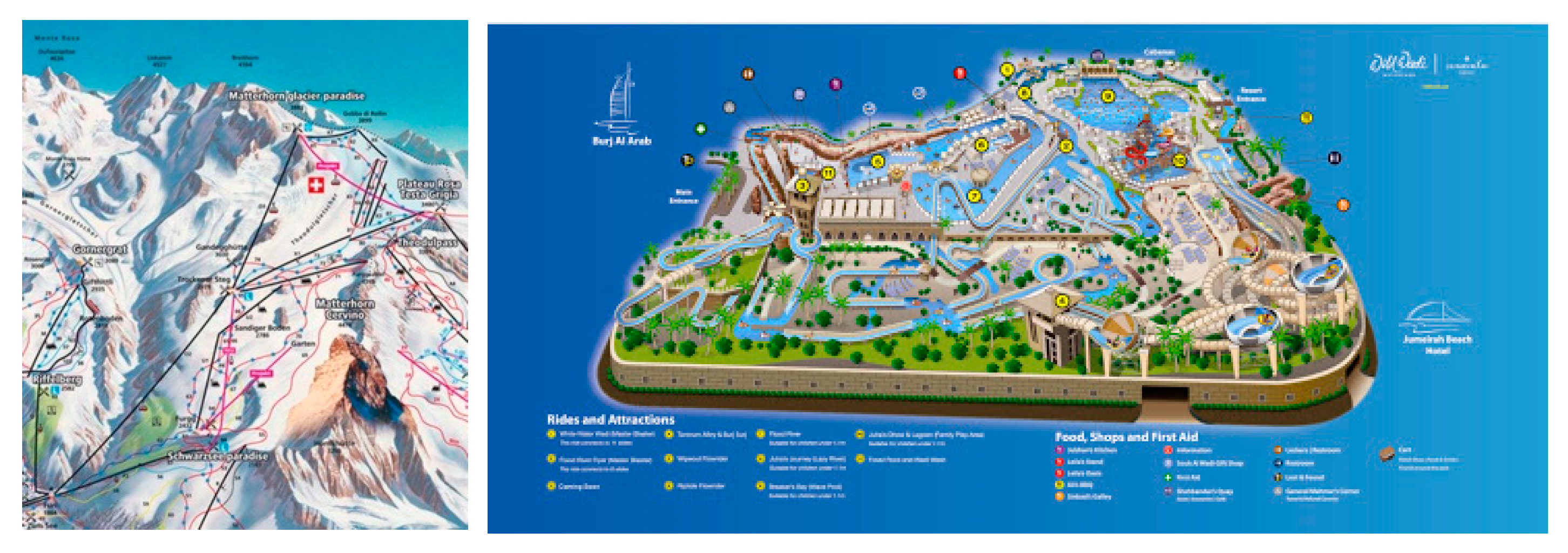
One of the specific types of thematic three-dimensional maps are projections in the form of plans for informational purposes (Figure 2). Their main feature is the visualization of a specific area in a 3D perspective, where all objects are presented in near-real shapes and dimensions and where the source data for the mapping has been obtained by various surveying techniques. A model example is Google Earth’s Street View. They are often used as a cartographic presentation of the area and objects in the area such as tourist guides, ski resorts maps, as well as plans of yacht ports. These types of maps play an important role in everyday life because, apart from the information they include, they allow the user to create a spatial orientation of a human relative to the surrounding space. Hence, they are often used for navigation purposes, i.e., moving in a defined direction or towards a specific target.
In addition to the issue of generalization of the content presented on maps, the need to visualize three-dimensional data is increasingly important. In this case, the existing mapping convention is not enough. The motivation to conduct the study was the need to jointly present the results of the measurement campaign carried out in April 2019 at the National Sailing Centre (NSC) of the Gdansk University of Physical Education and Sport (Poland) [29]. Taking into account the measurement methods used and the various types of spatial information generated, the authors set themselves the task of verifying the following research hypothesis: “it is possible to create a new type of map imaging that adapts selected features and functions of the thematic map to three-dimensional space”. The visualization presented in the paper maintains the uniqueness of the coordinates of flat points based on the cartographic projection used. An important added value of the study is the increase in the number of dimensions from two to three and the use of semiotic thematic maps to present one image spatial and descriptive data of various types.

2. Materials and Methods

The research data used to create three-dimensional thematic map imaging (T3DMI) were GNSS (Global Navigation Satellite System) technology measurements, terrestrial laser scanning (TLS) point cloud and bathymetric survey performed using an unmanned surface vehicle (USV) equipped with a single beam echosounder (SBES). Observations recorded by the devices had separate coordinate systems, hence it was necessary to harmonize the spatial data into one reference system. The transformation parameters were determined after identifying the coordinates of points representing the location of the same object in different data sets. After processing the source data, a perspective view was used to display them in the three-dimensional Euclidean space. Its advantage is obtaining a depth effect by assigning size to objects conditioned by their distances from the projection center. Depending on the adopted solution, the perspective projection can be created based on one, two or three points in space [30]. Unlike orthogonal projection, there are significant distance distortions in the perspective view. The mathematical foundations of both solutions are presented, among others in Carlbom and Paciorek [31] and Naus [32].

2.1. Measurement Data

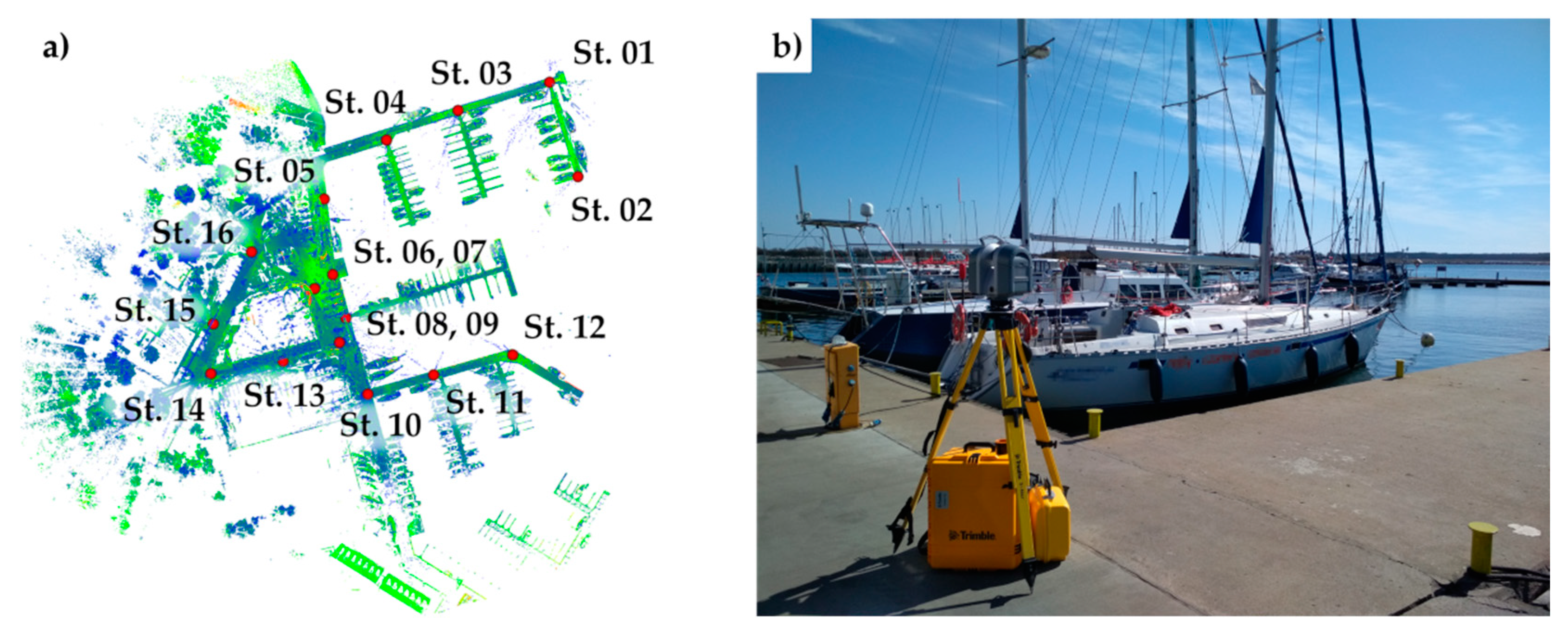
The terrestrial laser scanning method was used to obtain spatial data about the land objects of the marina of the NSC and objects on the water surface. The three-dimensional representation of infrastructural elements supplemented the bathymetric data. The instrument used, the Trimble TX8 scanner, was equipped with an optical module that enabled picture-taking of the environment and a designation of a color to individual measured points at the stage of data processing. 16 scanner stations were established in the marina area (Figure 3). For each point from the point cloud, the horizontal and vertical angles and the distance between the target and the device were measured. Based on the obtained observations, the coordinates of individual points in the local coordinate system of the station were calculated. It is worth noting that each measuring station had a separate coordinate system with an origin point in the laser emission and reception center. The planar orientation of the coordinate system resulted from the method (direction) of mounting the instrument on a tripod.
Each of the scans registered at the stations had a local coordinate system. To create a uniform point cloud for the entire marina, one of the local systems was adopted as the global system for all the point clouds. To perform this operation, it was necessary to replicate the same elements of the real world in the three-dimensional space of adjacent point clouds. The transformation control points were the coordinates of the centers of spherical markers (polystyrene spheres) located in the marina, ensuring optimal visibility from the measurement stations. Coordinates of points (centers of spheres) in local coordinate systems of the stations were used to determine the transformation parameters of every point cloud. The effect of the registration (connection) of point clouds was a coherent and geometrically correct set of spatial data representing the measured object. Registration error of 16-point clouds did not exceed 1 cm. The resulting spatial data set was a numerical representation of the marina technical infrastructure (Figure 4).
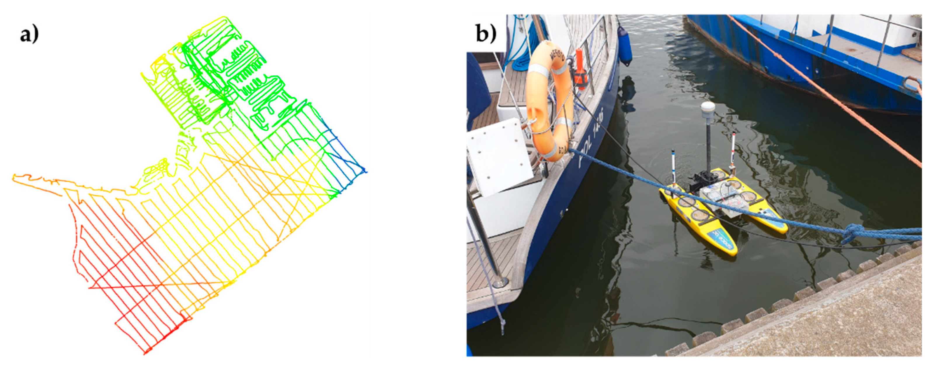
The second equally important spatial data set were bathymetric observations recorded by a single-beam echosounder SonarMite mounted on an unmanned surface vessel. Depth readings received a spatial and temporal assignment based on the positioning results of the Trimble R10 GNSS receiver. Satellite measurements carried out by the receiver were performed in the GNSS RTK differential mode using the VRSNet.pl active geodetic network. Bathymetric measurements were carried out in both manual and automatic mode, including setting the drone to follow given profiles. The method of manual navigation of the USV was used in the case of narrow and hard-to-reach areas of the marina basin. Bathymetric data recording locations are shown in Figure 5.
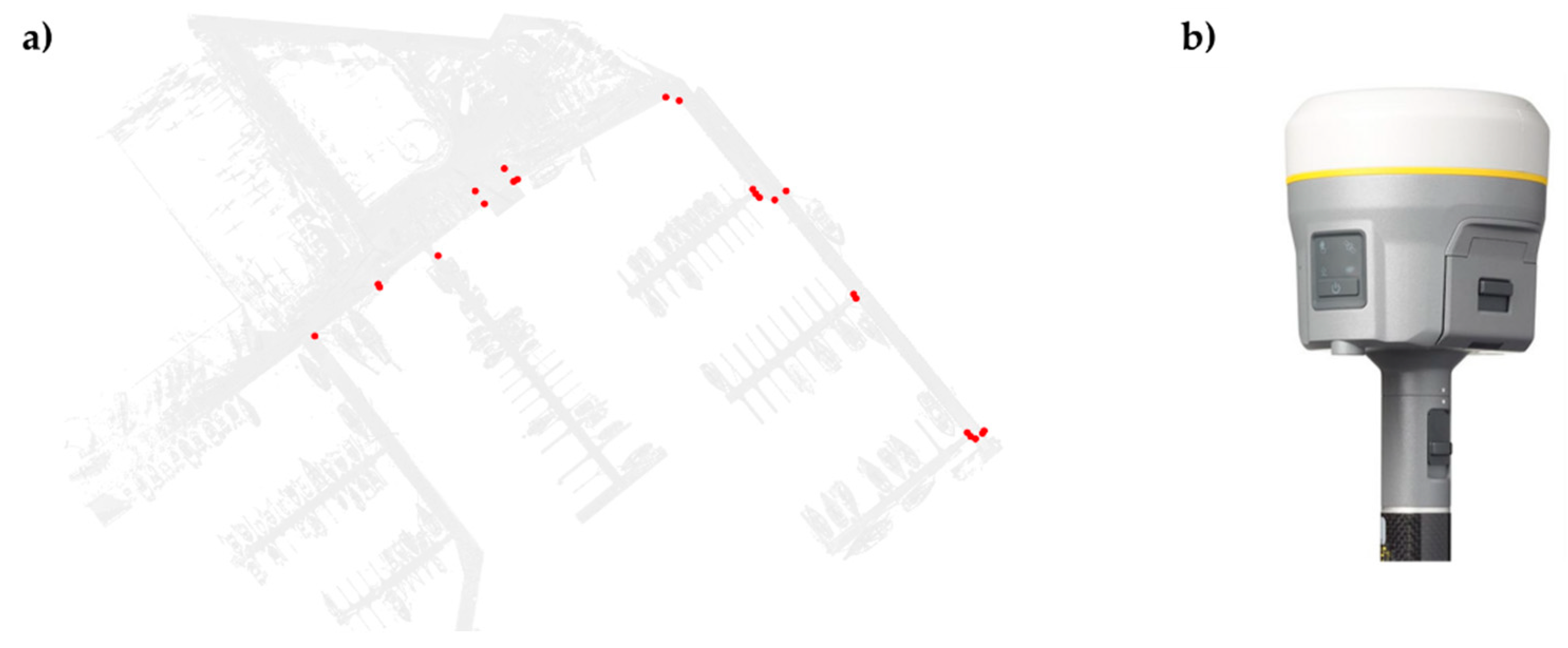
The GNSS RTK differential measurement method was also used to measure characteristic marina landmarks. The determined vertices coordinates of the border of selected elements of the quay infrastructure were reference points for the registered TLS point cloud. To determine the transformation parameters (scale parameter, rotation angle, and translation vector), selected quay elements measured with a GNSS receiver were identified in the point cloud space. The purpose of the operation, unlike the registration of TLS point clouds described above, was georeferencing the obtained spatial data set. The location of the measured control points of the characteristic points of the marina quay is shown in Figure 6.

2.2. Data Processing

The spatial data obtained in the measurement process had to be referenced to a single uniform coordinate system. This process, also known as harmonization, is an important element of geospatial analysis in the current state-of-the-art measuring techniques. The study used the Polish national plane coordinate system PL-2000. The PL-2000 system is a modification of the Gauss-Krüger projection, in which the mapping functions have the following form [33]:
x = k 0 N [ A + ( 1 T + C ) A 3 / 6 + ( 5 18 T + T 2 + 72 C 58 e 2 ) A 5 / 120 ]
y = k 0 { M M 0 + N tan φ [ A 2 / 2 + ( 5 T + 9 C + 4 C 2 ) ] A 4 / 24              + ( 61 58 T + T 2 + 600 C 330 e 2 ) A 6 / 720 }
where:
e 2 = e 2 / ( 1 e 2 ) ,
N = a / ( 1 e 2 sin 2 ϕ ) 1 / 2 ,
T = tan 2 ϕ ,
C = e 2 cos 2 ϕ ,
A = ( λ λ 0 ) cos ϕ ,
M = a [ ( 1 e 2 / 4 3 e 4 / 64 5 e 6 / 256 ) ϕ ( 3 e 2 / 8 + 3 e 4 / 32 + 45 e 6 / 1024 + ) sin 2 ϕ           + ( 15 e 4 / 256 + 45 e 6 / 1024 + ) sin 4 ϕ ( 35 e 6 / 3072 + ) sin 6 ϕ + ]
Modification of the original projection coordinates consists of changing the coefficient of scale change k0 from 1 to 0.999923 and the use of four meridional zones with a width of 3° and longitude of axial meridians λ0 of 15° E, 18° E, 21° E and 24° E, respectively. To distinguish the eastern coordinates in individual zones, the value of 500,000 m + (λ0/3°) ⋯ 1,000,000 m is added to the coordinate values. The Gauss-Krüger projection is shown in Figure 7.
The length and ellipsoidal width of the Geocentric curvilinear coordinates obtained by the GNSS RTK measurement were transformed into the PL-2000 system. Ellipsoidal heights were corrected for undulation of the PL-geoid-2011 geoid, which complements and refines the global geopotential model EGM2008 [34]. Selected characteristic points of the NCŻ AWFiS marina were assigned coordinates, taking into account georeference (Figure 6) and coordinates in the local coordinate system of the point cloud (Figure 3 and Figure 4). Based on the ICP method [35] and the SVD algorithm [36], the parameters of the transformation of the TLS point cloud coordinates were determined. The transformation matrix coefficients included the change in the scale of s, the translation vector T, and the rotation angle θ. The obtained parameter values were, respectively, s = 0.999998, TT = [6,550,742.821 m, 6,026,644.338 m, 1.878 m], θ = 291.8782°. The procedure of transformation of the TLS point cloud from the local coordinate system into the PL-2000 and normal height systems was carried out using the formula:
P = R Z ( ϑ ) P + T
where:
  • P , P —point coordinates vectors before and after transformation, respectively,
  • R Z ( ϑ ) —rotation matrix by the angle θ around the vertical axis OZ of the coordinate system,
  • T —translation vector.
Bathymetric data, in the form of depth measured with a single-beam echosounder, obtained positional data based on the coordinates determined by the Trimble R10 receiver. As in the case of determining the location of the characteristic points of the NSC marina quay, the receiver used the RTK GNSS differential measurement method. The known vertical offset between the GNSS receiver and the transducer, as well as the known depth of the SBES transducer, enabled the determination of the bottom elevation in the normal heights system. Thus, the second set of measured spatial data was harmonized to the coordinate system of the previous dataset. The next stage of bathymetric data processing was the preparation of a numerical seabed model using the Nearest Neighbor method [37]. Based on this method, the marina isobaths were also generated.
An inseparable element of the maps is a grid of images showing meridians and parallels. Based on this grid, the coordinates can be read and the impact of projection distortions on the content of the map can be assessed. To present the georeference of spatial data in the T3DMI visualization, a grid image of meridians and parallels with an interval of 5 arc seconds was used. The property of points located on the same meridian is a constant longitude value. Similarly, for the parallel, the latitude value is constant. Based on these relationships, the Gauss-Krüger projection and PL-2000 coordinate system formulas were used on the generated grid lines coordinates. The obtained points were assigned a zero-height value. Such a procedure was justified due to the presentation of the coastal sea basin, therefore the height values in the object’s area are close to zero. Therefore, there is no problem of a significant vertical distance between ground level and height reference level.

3. Results and Discussion

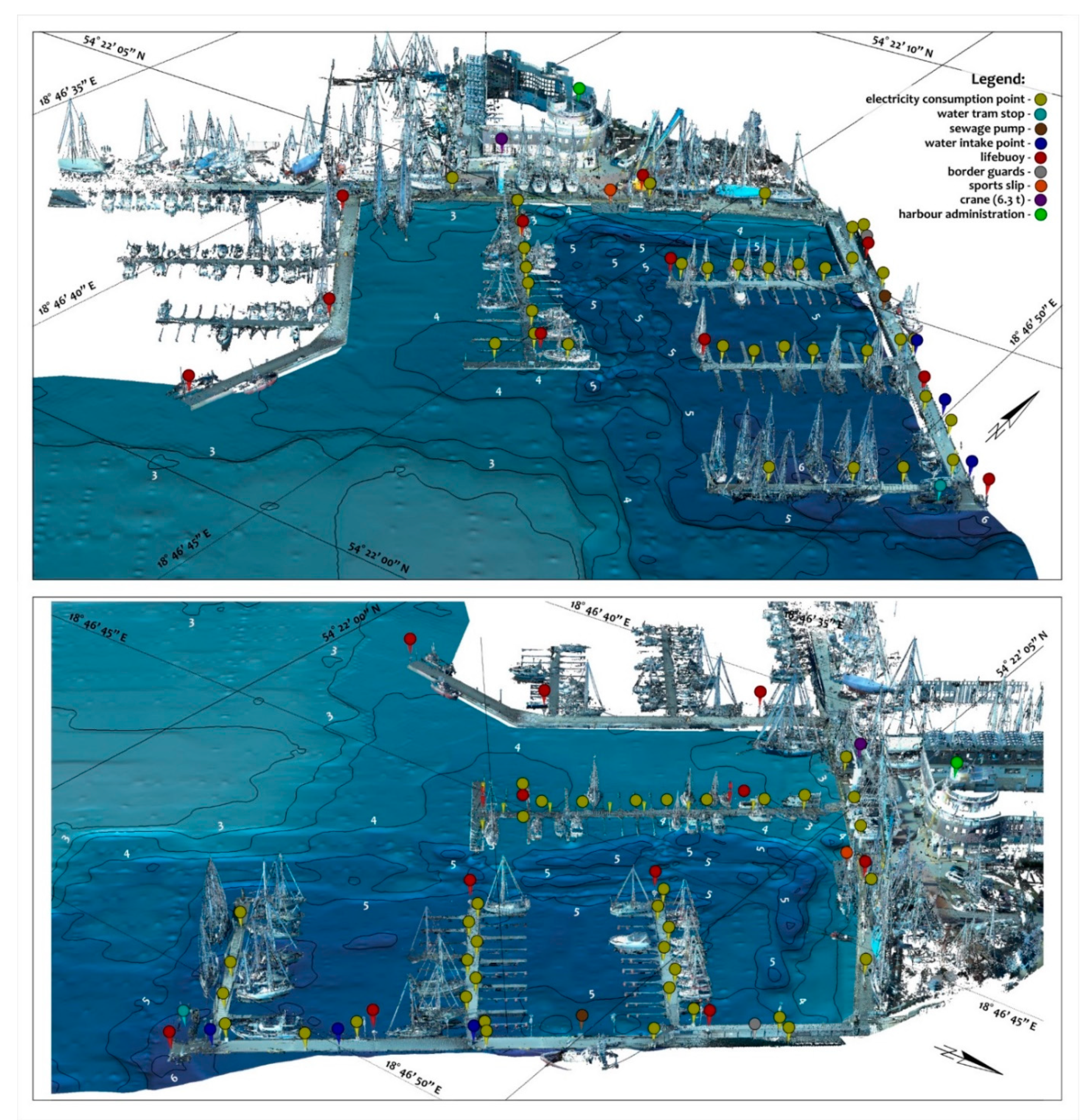
The result of the procedure for the harmonization of the laser scanning and bathymetric survey spatial data is shown in Figure 8. Due to the thematic nature of the study, the T3DMI visualization has been provided with an appropriate legend, presenting important objects from the viewpoint of the marina’s management. The grid of meridian and parallel images allow for the orientation of the presented content. The numerical model of the bottom of the basin has been enriched with labeled isobaths.
The above form of data presentation significantly increases the possibilities of interpretation. Three-dimensional space of the mapping and its content are adapted to current needs. The unique features of the presented type of 3D space imaging show a much higher degree of realism in their projection. The use of state-of-the-art measurement techniques ensured a high reliability of the source data and faithful representation of objects. As a result, the elements presented in the T3DMI image do not come from manual insertion in a graphics program, but from measurement. The exception here are labels indicating the location of selected marina points. Another feature of T3DMI imaging is the presence of elements that are unusual for other mappings. In this case, they are scanned parts of the yachts. The grid of meridians and parallels situated below the surveyed data provides the mapping user with geographical orientation in space. The above elements can also be a valuable material for presenting the environment in other navigational applications, e.g., car or tourist.
A feature of the T3DMI is the user-customizable view. Depending on needs of the viewer, the orthogonal or perspective projection is available. The top orthogonal view of the T3DMI model, combined with the parametric lines of the coordinate system and after adding the optional element of a linear scale, permits the creation of an image which corresponds with classic thematic maps [13]. The added value of the T3DMI to a two-dimensional map is the possibility of changing to a perspective view with the desired position of the projection center [38]. Adding the possibility of placing additional descriptive objects in the three-dimensional space of the model, the user gains the option of creating projections focused on a specific aspect of space. In both cases, based on the three-dimensional model, the obtained graphic datasets can be used in analog paper form or electronic graphic files.
When discussing the features and benefits of T3DMI, it is important to mention the related matter of Virtual Reality (VR). The rapid development of the technology of measuring devices, hardware computer components, firmware, and software has contributed to the creation of a new way of presenting graphic data— to replace monitors with VR headsets. Combined with the appropriate inertial sensors, a user obtains a unique experience that significantly differs from viewing the screen of a typical monitor. Many researchers were involved in the comparison and evaluation of VR sets, eg. Papachristos et al. [39] or Froehlich and Azhar [40].
Throughout the literature, there are publications which present the methodology behind creating three-dimensional models and displaying them in VR technology. Walmsley and Kersten [41] presented the results of the study using a combination of TLS and photogrammetric technologies. An important element of the study was the creation of models based on point clouds. As a result, three-dimensional visualizations of the object were obtained, whereby the user can virtually relocate in the area with the use of a VR headset. In another study, Edler et al. [42] presented the application of this technology in a revitalized post-industrial area. An important element of the work was the use of GIS data to reconstruct the terrain model. The work [43] is also noteworthy, where an important direction in the development of VR technology was observed, consisting of adding sound to the visual data.
In the context of state-of-the-art, it should be noted that T3DMI is a three-dimensional model, so it can also be used for real-time presentation of the temporal situation of the area in VR technology. This is a potential direction for future work. An important limitation of real-time visualization is the large size of point clouds, which makes it advisable to create three-dimensional models, as presented in [41]. The added value of the T3DMI is the presence of the bathymetric model and the georeferencing of all spatial data included in the model.

4. Conclusions

The study proved the effectiveness of the proposed methods for spatial imaging of the terrain surface and the bottom of the marina. In many cases, classic maps, due to their two-dimensional nature, do not allow for a clear representation of several elements on a single image. This problem is particularly notable from the perspective of the current and future development of measuring devices collecting spatial data. The authors in the study combined the current state of knowledge and technology to create three-dimensional thematic map visualization (T3DMI).
The resulting harmonized dataset, consisting of the TLS point cloud, bathymetric survey, and the bottom model with isobaths is a comprehensive representation of both the seabed and land objects. The three-dimensional numerical properties of the data enable wide access to spatial information about the marina. Working in the georeferenced point cloud space not only allows for the calculation of geometric measures (distance, area, volume) but also the reading of the values of horizontal and vertical orthogonal coordinates. An additional grid of images of meridians and parallels indicate the values of the curvilinear coordinates of latitude and longitude.
Given the feature of a wide spectrum of thematic map applications, T3DMI imaging has been profiled for the information needs of the NSC marina. The location of the key objects for marina management was defined using selected projections. The use of a perspective view is a new quality of map imaging that serves as a kind of three-dimensional thematic map. It should be clearly emphasized here that the classic map definition only applies to two-dimensional imaging, hence the terming T3DMI as a map would be incorrect. The combined representation of separate elements of the real world in the form of a single spatial dataset is a new quality of imaging.
Further research directions of the proposed solution could be the creation of an interactive database, which should be updated at regular intervals. An important functional element would be providing access to the database in the form of a mobile application. Using the example of the T3DMI of the marina described in the publication, the user would be able to assess the possibility and safety of mooring to the quay. The application could have additional functionality in the form of free berths. An important limitation for internet data transmission is the large size of point clouds. However, the preparation and implementation of three-dimensional models in the database would significantly minimize this problem.
The added value of the study is to suggest a new way of presenting both the Earth’s surface and natural or anthropogenic objects. The solution presented by the authors combines both theoretical and practical aspects of the issue. The process of creating T3DMI visualization uses, among other mathematical properties of cartographic projections, the theory of height systems, three-dimensional coordinate transformations, and advanced methods of spatial modeling. The spatial dataset can be used as a universal basis for creating other products dedicated to the individual needs of recipients. Given the rapid development of measurement technologies, the presented methodology of spatial data processing is an important direction in object visualization, using selected features of cartographic mappings.

Author Contributions

Conceptualization, C.S. and P.S.D.; Methodology, P.S.D.; Software, P.S.D.; Validation, C.S., M.S. and A.M.; Formal Analysis, P.S.D.; Investigation, P.S.D.; Resources, A.M., M.S. and P.S.D.; Data Curation, A.M., M.S. and P.S.D.; Writing—Original Draft Preparation, P.S.D.; Writing—Review & Editing, P.S.D., C.S., M.S. and A.M.; Visualization, P.S.D.; Supervision, C.S. and A.M.; Project Administration, C.S.; Funding Acquisition, C.S. All authors have read and agreed to the published version of the manuscript.

Funding

This research was funded from the statutory activities of Gdynia Maritime University, grant number WN/2021/PZ/05.

Institutional Review Board Statement

Not applicable.

Informed Consent Statement

Not applicable.

Data Availability Statement

Not applicable.

Conflicts of Interest

The authors declare no conflict of interest.

References

  1. Bagrow, L. History of Cartography; Routledge: New York, NY, USA, 2017. [Google Scholar]
  2. Bugayevskiy, L.M.; Snyder, J. Map Projections: A Reference Manual; CRC Press: Boca Raton, FL, USA, 1995. [Google Scholar]
  3. Robinson, A.H. Elements of Cartography; John and Wiley and Sons: Hoboken, NJ, USA, 1995. [Google Scholar]
  4. Maling, D.H. Coordinate Systems and Map Projections; Elsevier: Amsterdam, The Netherlands, 2013. [Google Scholar]
  5. Hooijberg, M. Practical Geodesy: Using Computers; Springer Science & Business Media: Berlin/Heidelberg, Germany, 2012. [Google Scholar]
  6. Peterson, G.N. GIS Cartography: A Guide to Effective Map Design; CRC Press: Boca Raton, FL, USA, 2014. [Google Scholar]
  7. Tyner, J.A. Principles of Map Design; Guilford Publications: New York, NY, USA, 2014. [Google Scholar]
  8. Monmonier, M. Rhumb Lines and Map Wars: A Social History of the Mercator Projection; University of Chicago Press: Chicago, IL, USA, 2010. [Google Scholar]
  9. Morgaś, W.; Kopacz, Z. Conversion of geodetic coordinates into flat (2-dimensional) coordinates PL-UTM for the purposes of navigation. Sci. J. Pol. Nav. Acad. 2017, 208, 45–60. [Google Scholar]
  10. Deakin, R.E.; Hunter, M.N.; Karney, C.F.F. The Gauss-Krüger projection. In Proceedings of the 23rd Victorian Regional Survey Conference, Warrnambool, Australia, 10–12 September 2010; pp. 1–20. [Google Scholar]
  11. Dent, B.D.; Torguson, J.S.; Holder, T.W. Cartography: Thematic Map Design; McGraw Hill Higher Education: Boston, MA, USA, 2009. [Google Scholar]
  12. Slocum, T.A.; MacMaster, R.B.; Kessler, F.C.; Howard, H.H. Thematic Cartography and Geovisualization, 3rd ed.; Pearson Prentice Hall: Hoboken, NJ, USA, 2009. [Google Scholar]
  13. Żyszkowska, W. Levels and properties of map perception. Pol. Cartogr. Rev. 2017, 49, 17–26. [Google Scholar] [CrossRef] [Green Version]
  14. Kraak, M.J.; Ormeling, F. Cartography: Visualization of Spatial Data; Guilford Press: New York, NY, USA, 2011. [Google Scholar]
  15. DiBiase, D. Visualization in the earth sciences. Earth Miner. Sci. 1990, 59, 13–18. [Google Scholar]
  16. Dabrowski, P.S.; Specht, C. Spatial expansion of the symmetrical objects point clouds to the lateral surface of the cylinder—Mathematical model. Measurement 2019, 134, 40–47. [Google Scholar] [CrossRef]
  17. Specht, M.; Specht, C.; Mindykowski, J.; Dąbrowski, P.; Maśnicki, R.; Makar, A. Geospatial Modeling of the Tombolo Phenomenon in Sopot using Integrated Geodetic and Hydrographic Measurement Methods. Remote Sens. 2020, 12, 737. [Google Scholar] [CrossRef] [Green Version]
  18. Dąbrowski, P.S.; Specht, C.; Felski, A.; Koc, W.; Wilk, A.; Czaplewski, K.; Karwowski, K.; Jaskólski, K.; Specht, M.; Chrostowski, P.; et al. The Accuracy of a Marine Satellite Compass under Terrestrial Urban Conditions. J. Mar. Sci. Eng. 2020, 8, 18. [Google Scholar] [CrossRef] [Green Version]
  19. Specht, C.; Lewicka, O.; Specht, M.; Dąbrowski, P.; Burdziakowski, P. Methodology for Carrying Out Measurements of the Tombolo Geomorphic Landform Using Unmanned Aerial and Surface Vehicles near Sopot Pier, Poland. J. Mar. Sci. Eng. 2020, 8, 384. [Google Scholar] [CrossRef]
  20. Specht, C.; Dąbrowski, P.; Dumalski, A.; Hejbudzka, K. Modeling 3D Objects for Navigation Purposes Using Laser Scanning. TransNav: Int. J. Mar. Navig. Saf. Sea Transp. 2016, 10. [Google Scholar] [CrossRef]
  21. Vasilev, S. Who is Who’ on the Map? In Proceedings of the 1st International Trade Fair of Geodesy, Cartography, Navigation and Geoinformatics GEOS 2006, Prague, Czech Republic, 1–3 March 2007. [Google Scholar]
  22. Friendly, M. 1995. Milestones in the History of Thematic Cartography, Statistical Graphics, and Data Visualization. In Proceedings of the 13th International Conference on Database and Expert Systmes Applications (DEXA 2002), Aix-en-Provence, France, 2–6 September 2002; pp. 59–66. [Google Scholar]
  23. Tennekes, M. Tmap: Thematic Maps in R. J. Stat. Softw. 2018, 84, 1–39. [Google Scholar] [CrossRef] [Green Version]
  24. Góralski, R. Three-Dimensional Interactive Maps Theory and Practice, A Submission Presented in Partial Fulfilment of the Requirements of the University of Glamorgan/Prifysgol Morgannwg for the Degree of Doctor of Philosophy. 2009. Available online: https://core.ac.uk/reader/9653382 (accessed on 4 May 2020).
  25. Van Driel, N.J. Three dimensional display of geologic data. In Three Dimensional Applications in Geographical Information Systems; Raper, J., Ed.; CRC Press: Boca Raton, FL, USA, 1989. [Google Scholar]
  26. Musliman, I.A.; Abdul-Rahman, A.; Coors, V. 3D Navigation for 3D-GIS—Initial Requirements. In Innovations in 3D Geo Information Systems; Abdul-Rahman, A., Zlatanova, S., Coors, V., Eds.; Springer: Berlin/Heidelberg, Germany, 2006. [Google Scholar]
  27. Schilling, A.; Coors, V.; Giersich, M.; Aasgaard, R. Introducing 3D GIS for the Mobile Community—Technical Aspects in the Case of TellMaris; IMC Workshop on Assistance, Mobility, Applications: Stuttgart, Germany, 2003. [Google Scholar]
  28. Kraak, M.J. Visual exploration of virtual environments. In Virtual Reality in Geography; Unwin, D., Fisher, P., Eds.; Taylor & Francis: Abingdon, UK, 2002. [Google Scholar]
  29. Makar, A.; Specht, C.; Specht, M.; Dąbrowski, P.; Szafran, M. Integrated Geodetic and Hydrographic Measurements of the Yacht Port for Nautical Charts and Dynamic Spatial Presentation. Geosciences 2020, 10, 203. [Google Scholar] [CrossRef]
  30. Mitchell, W.J.; McCullough, M. Digital Design Media; John Wiley & Sons: Hoboken, NJ, USA, 1995. [Google Scholar]
  31. Carlbom, I.; Paciorek, J. Planar geometric projections and viewing transformations. ACM Comput. Surv. (CSUR) 1978, 10, 465–502. [Google Scholar] [CrossRef] [Green Version]
  32. Naus, K. Electronic navigational chart as an equivalent to image produced by hypercatadioptric camera system. Pol. Marit. Res. 2015, 22, 3–9. [Google Scholar] [CrossRef] [Green Version]
  33. Snyder, J.P. Map Projections—A Working Manual; US Government Printing Office: Washington, DC, USA, 1987; Volume 1395.
  34. Pavlis, N.K.; Holmes, S.A.; Kenyon, S.C.; Factor, J.K. An earth gravitational model to degree 2160: EGM2008. EGU Gen. Assem. 2008, 10, 13–18. [Google Scholar]
  35. Pomerleau, F.; Colas, F.; Siegwart, R.; Magnenat, S. Comparing ICP variants on real-world data sets. Auton. Robot. 2013, 34, 133–148. [Google Scholar] [CrossRef]
  36. Kalman, D. A singularly valuable decomposition: The SVD of a matrix. Coll. Math. J. 1996, 27, 2–23. [Google Scholar] [CrossRef]
  37. Olivier, R.; Hanqiang, C. Nearest neighbor value interpolation. Int. J. Adv. Comput. Sci. Appl. 2012, 3, 25–30. [Google Scholar] [CrossRef] [Green Version]
  38. Wolf, P.R.; Dewitt, B.A.; Wilkinson, B.E. Elements of Photogrammetry with Applications in GIS; McGraw-Hill Education: New York, NY, USA, 2014. [Google Scholar]
  39. Papachristos, N.M.; Vrellis, I.; Mikropoulos, T.A. A comparison between oculus rift and a low-cost smartphone VR headset: Immersive user experience and learning. In Proceedings of the 2017 IEEE 17th International Conference on Advanced Learning Technologies (ICALT), Timisoara, Romania, 3–7 July 2017; IEEE: New York, NY, USA, 2017; pp. 477–481. [Google Scholar]
  40. Froehlich, M.A.; Azhar, S. Investigating virtual reality headset applications in construction. In Proceedings of the 52nd Associated Schools of Construction Annual International Conference, Provo, UT, USA, 13–16 April 2016; Volume 52, pp. 13–16. [Google Scholar]
  41. Walmsley, A.P.; Kersten, T.P. The IMPERIAL Cathedral in Königslutter (Germany) as an immersive experience in virtual reality with integrated 360 panoramic photography. Appl. Sci. 2020, 10, 1517. [Google Scholar] [CrossRef] [Green Version]
  42. Edler, D.; Keil, J.; Wiedenlübbert, T.; Sossna, M.; Kühne, O.; Dickmann, F. Immersive VR experience of redeveloped post-industrial sites: The example of “Zeche Holland” in Bochum-Wattenscheid. KN-J. Cartogr. Geogr. Inf. 2019, 69, 267–284. [Google Scholar] [CrossRef] [Green Version]
  43. Hruby, F. The sound of being there: Audiovisual cartography with immersive virtual environments. KN-J. Cartogr. Geogr. Inf. 2019, 69, 19–28. [Google Scholar] [CrossRef] [Green Version]
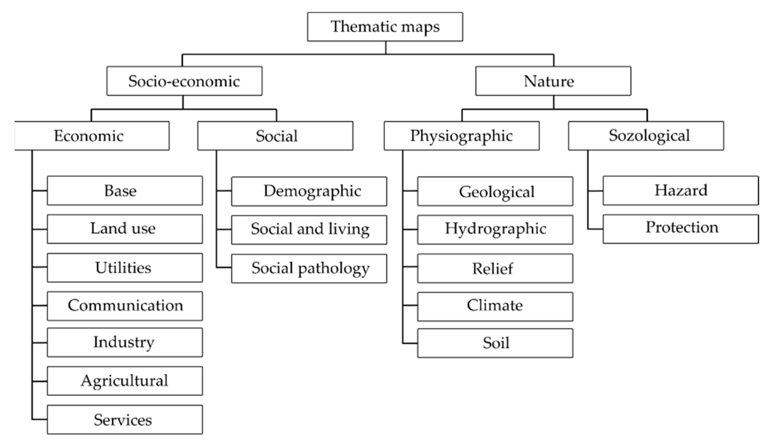
Figure 1. The division of thematic maps.
Applsci 11 07016 g001
Figure 2. Examples of three-dimensional plans (sources: https://www.europe-mountains.com/, http://www.dubaiattractions.biz/ accessed on 3 May 2020).
Applsci 11 07016 g002
Figure 3. Location of 16 stations on the background of the point cloud (a) and the Trimble TX-8 laser scanner during a measurement (b).
Applsci 11 07016 g003
Figure 4. Perspective view of the registered point cloud of the marina.
Applsci 11 07016 g004
Figure 5. Depth measurement locations (a) and devices used in the bathymetric survey (b).
Applsci 11 07016 g005
Figure 6. Characteristic control points of the marina quay (a) measured by the GNSS RTK method with the Trimble R10 receiver (b) (source: www.geotronics.com.pl accessed on 4 May 2020).
Applsci 11 07016 g006
Figure 7. Gauss-Krüger projection of the world (a) and Central and Eastern Europe for the 19° E meridian (b).
Applsci 11 07016 g007
Figure 8. Three-dimensional map imaging (T3DMI) visualization of the National Sailing Centre (NSC) marina.
Applsci 11 07016 g008
Publisher’s Note: MDPI stays neutral with regard to jurisdictional claims in published maps and institutional affiliations.