Article

Bending Properties of Lightweight Copper Specimens with Different Infill Patterns Produced by Material Extrusion Additive Manufacturing, Solvent Debinding and Sintering

by
Joamin Gonzalez-Gutierrez
1,2,*,
Santiago Cano
1,
Josef Valentin Ecker
3,
Michael Kitzmantel
4,
Florian Arbeiter
5,
Christian Kukla
6,* and
Clemens Holzer
1
1
Department of Polymer Engineering and Science, Institute of Polymer Processing, Montanuniversitaet Leoben, Otto Gloeckel-Str. 2, 8700 Leoben, Austria
2
Functional Polymers Unit, Material Research and Technology Department, Luxembourg Institute of Science and Technology, 5 rue Bommel, 4940 Hautcharage, Luxembourg
3
Center of Digitalisation, Research and Development, Fill GmbH, Zukunftsstraße 2, 4942 Gurten, Austria
4
RHP-Technology GmbH, Austrian Research and Technology Center, 2444 Seibersdorf, Austria
5
Department of Polymer Engineering and Science, Institute of Material Science and Testing of Polymers, Montanuniversitaet Leoben, Otto Gloeckel-Str. 2, 8700 Leoben, Austria
6
Industrial Liaison Department, Montanuniversitaet Leoben, Peter Tunner-Str. 27, 8700 Leoben, Austria
*
Authors to whom correspondence should be addressed.
Appl. Sci. 2021, 11(16), 7262; https://doi.org/10.3390/app11167262
Submission received: 12 July 2021 / Revised: 30 July 2021 / Accepted: 4 August 2021 / Published: 6 August 2021
(This article belongs to the Special Issue Multi-Material Additive Manufacturing)

Abstract

:

Featured Application

Additive manufacturing of lightweight structures in copper.

Abstract

Material extrusion additive manufacturing (MEX) is a versatile technology for producing complex specimens of polymers, ceramics and metals. Highly-filled filaments composed of a binder system and a high-volume content of sinterable powders are needed to produce ceramic or metal parts. After shaping the parts via MEX, the binder is removed and the specimens are sintered to obtain a dense part of the sintered filler particles. In this article, the applicability of this additive manufacturing process to produce copper specimens is demonstrated. The particular emphasis is on investigating the production of lightweight specimens that retain mechanical properties without increasing their weight. The effect of infill grades and the cover presence on the debinding process and the flexural properties of the sintered parts was studied. It was observed that covers could provide the same flexural strength with a maximum weight reduction of approximately 23%. However, a cover on specimens with less than 100% infill significantly slows down the debinding process. The results demonstrate the applicability of MEX to produce lightweight copper specimens.

1. Introduction

Additive manufacturing (AM) has the potential to be a flexible production method that can be used for the fabrication of personalized products with low weight, tailored mechanical, electrical, thermal, and medicinal properties for numerous applications [1]. For these reasons, AM has gained importance in academic and industrial research in the last 20 years. Among the materials used in AM, metals are still the most important ones [2]. One metal that could benefit from being processed by AM is pure copper.
Copper and its alloys have a very high thermal and electrical conductivity, making them good candidates for thermal and electrical management systems [3]. Additionally, copper and its alloys have antibacterial and antiviral properties [4,5]. Combining these properties with the design freedom that AM brings can result in the possibility of manufacturing efficient heat exchanger devices and complex electrically conductive paths in electronics [3] and fixtures that can prevent the spread of diseases [5]. The most common techniques used for the additive manufacturing of metals are powder bed fusion (PBF) techniques. It has been observed that using PBF with copper is challenging due to its high thermal conductivity, leading to a very high thermal dissipation during processing, which causes residual stresses [6,7]. Copper also has a high reflectivity to laser light, making selective laser melting (SLM) of pure copper problematic, and is mainly used in copper alloys with lower thermal conductivity and lower reflectivity [3,7,8,9]. This limitation is sometimes overcome by using laser beams with greater power (1000 W). By doing so, densities up to 99.9% from the theoretical can be obtained with SLM [10]. Another possibility is to coat the powder with polymers followed by a debinding and sintering step [11], but the density and purity of the final part can be lower than expected [12]. The fabrication of copper parts by electron beam melting (EBM) works quite well since the absorption and reflection of electrons are different from those of photons [3,13]. Thus, most of the energy transferred by the electrons is absorbed within the copper particles. The energy deposited is sufficient to consolidate pure copper with very high thermal conductivity (400 W m/K) [3,14]. The high thermal conductivity of copper requires heating the powder bed to minimize defects caused by the severe thermal energy dissipation during the melting process. However, due to the high sintering activity of copper powder, there is a danger that the loose powder cannot be removed if the pre-heating is conducted at a high temperature or for a very long time [3]. In addition, there is a high capital cost of beam-based AM equipment and the infrastructure needed to handle explosive powders safely. These complexities have led to the development of other binder-based AM processing routes for copper specimen fabrication [7,11].
Copper parts can be indirectly, additively manufactured by other non-beam methods, such as material jetting (MJT), vat photopolymerization (VPP), binder jetting (BJT) and material extrusion (MEX) [11,15], followed by the removal of the organic binder and the sintering of the debound parts. The most common ones are BJT and MEX. Binder Jetting is an AM method where a liquid binding agent is selectively deposited to join particles temporarily. The non-bound powder acts as a support material for overhangs, and it is removed by compressed air. The shaped part is cured for better handling and taken to a sintering furnace where the binder is pyrolyzed and the particles sintered through atomic diffusion [16]. Binder jetting is a scalable process very well suited for lots with numerous small parts with complex geometry. However, as with other powder bed technologies, the flowability of the powder is crucial to achieving geometrical accuracy and low porosity. A good flowability is generally achieved by using larger particles, but smaller particles sinter more easily. Researchers have shown that multimodal powder distributions can increase flowability and final sintered density [17]. Therefore, unique particle size distributions are needed for BJT, and these special distributions increase the cost of the powder [16,18]. In addition, relative to MEX, BJT equipment is more costly [19]. Thus, for low-volume applications of medium-sized specimens, MEX could be a more economical alternative.
The most common type of MEX additive manufacturing is a relatively simple process that uses filaments as starting materials. The material with a liquid-like consistency is pushed through a die and then selectively deposited, layer-by-layer, to shape a three-dimensional object [15]. MEX allows the production of complex-shaped parts not only from thermoplastics [20], fiber-filled composites [21], and low melting point (~450 °C) metallic alloys [22], but also from high-melting-point (>1000 °C) metallic alloys [15,23,24,25,26,27,28,29,30], such as copper [31], ceramics [15,32,33,34,35,36,37,38,39], and hard metals and cermets [40,41,42]. Highly-filled thermoplastic filaments are used as the feedstock material to obtain metallic, ceramic and cermet parts. As is the case with binder jetting, the shaped part is then subjected to a process of binder removal [43,44] and sintering to densify the parts [15]. Recently, new machines that can work with pellets of metal injection molding (MIM) feedstocks have been developed, and research is being carried out to maximize the performance of the printed specimens with steels [45], hard metals [40], and copper [46]. The advantages of using filament feedstocks are low-cost shaping equipment [47], availability of powders used in traditional powder metallurgical processes, and same feedstock materials are usable in metal injection molding (MIM) or metal extrusion molding (MEM) [48]. It is also easy to prepare multi-material parts when co-sintering is possible [15,49,50]. The main disadvantage of using filaments as feedstock is that binder systems must be adjusted to have enough mechanical strength and flexibility so the filament can be reliably processed in standard commercial MEX machines. Nevertheless, new binders are available, and filaments with copper and other sinterable powders have been reported in the literature [15,29,31,32,39,49,51,52,53,54,55,56,57,58,59,60,61,62,63,64]. Therefore, due to the increasing popularity of filament-based MEX, this technique was selected for shaping copper specimens in this study.
Many studies available in the literature concentrate on producing parts as dense as possible since the density is directly related to the mechanical performance and the conductivity of the specimens. For example, the thermal and electrical conductivities of specimens shaped by MEX and sintering have been discussed previously by Ebrahimi and Ju [31]. They observed that the tensile properties of sintered copper parts were consistent with other sintering approaches once the porosity of the parts is considered [31]. This investigation focuses on producing copper specimens that are not 100% dense; that is, one of the main advantages of additive manufacturing, i.e., the fabrication of lightweight specimens with different infill patterns. The production and characterization of copper parts with different infill grades and patterns by MEX, solvent debinding and sintering is here presented. A unique feedstock material with 55 vol.% of copper particles was prepared using a proprietary binder. A particular emphasis is placed on studying the debinding rates with solvents and flexural mechanical properties depending on printing patterns, infill degrees, and covers to prepare hollow specimens. The current study aims to close the gap of the lack of material properties for materials and components produced by MEX debinding and sintering that are not necessarily 100% dense. It aims to provide additional guidelines for the fabrication of lightweight specimens.

2. Materials and Methods
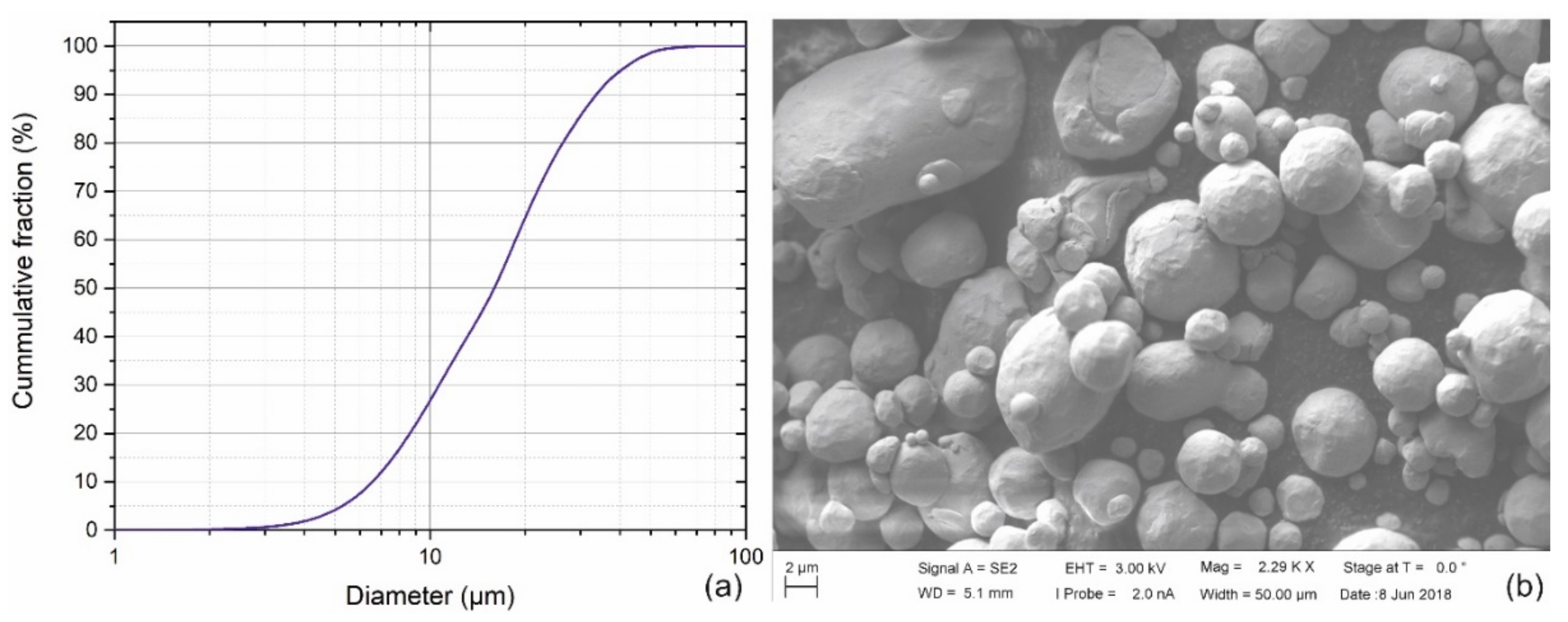
2.1. Materials

The same binder system was used to obtain sinterable feedstocks with steels [25,26], hard metal [40], cermet [40], zirconia [35] and alumina [64] is used in this study. A thermoplastic elastomer—TPE (Kraiburg TPE GmbH & Co. KG, Waldkraiburg, Germany) and a grafted polyolefin—gPO (BYK-Chemie GmbH, Wesel, Germany) were combined to prepare the binder system in the feedstock for this investigation. A 99.9% pure copper gas atomized powder was used as the filler in the feedstock (Carpenter Powders Products Inc., Woonsocket, RI, USA). The cumulative particle size distribution given by the supplier and a Scanning Electron Microscopy (SEM) image of the powder is shown in Figure 1. The percentile ranks of the powder were: D10 = 6.8 µm, D50 = 16 µm and D90 = 33.6 µm.

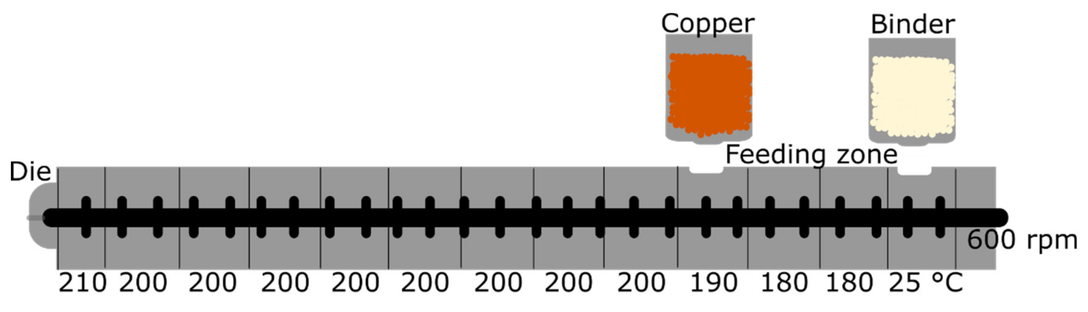
2.2. Feedstock and Filament Preparation

The binder was prepared by pre-mixing the pellets of TPE and gPO in a solid state. This pre-mixture was then extruded in a single screw extruder (FT-E20T-MP-IS, Dr. Collin GmbH, Maitenbeth, Germany) equipped with a round die of 1.75 mm in diameter. The screw rotational speed was set to 70 rpm; the temperature was set in the feeding zone to 180 °C, 195 °C in the melting zone, and 200 °C in the metering zone; the die temperature was also 200 °C. The extruded binder was cooled down in a water bath and later granulated in a strand pelletizer (SGS 50-EL, Scheer Reduction Engineering GmbH, Grossostheim, Germany). Before further processing, the binder was dried overnight in an air dryer (Wittmann Technology GmbH, Vienna, Austria) at 60 °C.
The copper feedstock was prepared with a powder content of 55 vol% or 92 wt% in a co-rotating, twin-screw extruder (ZSE 18 HP-48D, Leistritz Extrusionstechnik GmbH, Nuremberg, Germany) with two gravimetric feeding units (DDW-M-DSR28, Brabender Technologie GmbH, Duisburg, Germany). The binder was placed in the first feeding unit and the metal powder in the second unit. The screw rotational speed was set to 600 rpm, and temperatures from the feeding zone to the die were 25, 180, 180, 190, 200, 200, 200, 200, 200, 200, 200, 200, and 210 °C (Figure 2). The extrudate was transported on an air-cooled conveyor belt (Reduction Engineering Scheer, Kent, OH, USA) and pelletized in the strand pelletizer described above.
Filaments were prepared in the same single screw extruder (FT-E20T-MP-IS), in which the binder was prepared, equipped with a round die of 1.75 mm in diameter and 20 mm in length. However, the extrudate was not water-cooled but cooled down by natural convection during the transportation on a conveyor belt (GAL-25, Geppert-Band GmbH, Jülich, Germany) and a haul-off unit (self-developed). After the haul-off unit, the extruded filament’s diameter and ovality were measured at 1.75 ± 0.05 mm and <0.1 mm, respectively, by a diameter measurement device and a processor (Sikora Laser 2010T and EcoControl 600, Sikora AG, Bremen, Germany). The filaments were stored in spools. The extrusion temperatures from the feeding zone to the die were 180, 190, 195 and 200 °C, and the rotational speed was 85 rpm.

2.3. Material Extrusion Additive Manufacturing

Three-dimensional printing trials were performed on the filament-based MEX machine X1000 (German RepRap GmbH, Feldkirchen, Germany). The printing parameters were selected: Nozzle diameter 0.6 mm, layer height 0.3 mm, printing speed 30 mm/s, extrusion temperature 240 °C, platform temperature 90 °C, and platform material glass mirror coated with DimaFix adhesion spray (DIMA 3D S.L., Valladolid, Spain). Bending specimens with a rectangular cross-section were printed (L = 80 mm, w = 10 mm, h = 4 mm). The degree of infill, infill pattern and presence of a cover layer with a 100% diagonal (45° with respect to the longest dimension of the bar) infill were varied, as shown in Table 1. All specimens had two perimeters. Six specimens per type of geometry were printed, and solvent debound, but not all of them were sintered since all did not fit in the sintering furnace. The notation used in the manuscript to identify the different series is also shown in Table 1.

2.4. Debinding and Sintering

The binder system is composed of a cyclohexane soluble polymeric component (TPE) and an insoluble backbone (gPO). The removal of the soluble component was investigated as a function of the debinding time for the different printed specimens. Therefore, the printed specimens were immersed in cyclohexane at 60 °C, taken out after a specific time, and dried for at least 4 h in a fume hood at room temperature. After drying, the specimens were weighed, and the mass was recorded. After weighing, the specimens were immersed once again. The sequence of the immersion times was 1, 2, 3, 3, 3, 6 and 6 h, with accumulated debinding times in the solvent of 1, 3, 6, 9, 12, 18 and 24 h, respectively. At least three specimens per geometry were debound.
After solvent debinding, the specimens were thermally debound and sintered; this was done in an Elnik MIM3000L furnace (Elnik Systems LLC, Cedar Grove, NJ, USA) with a hydrogen atmosphere. Specimens were sintered on top of a porous alumina plate. The thermal debinding and sintering profile is shown in Figure 3.

2.5. Bending Tests

The printed specimens were tested in a 3-point bending setup according to ISO 178, which is usually applied to polymeric samples to be comparable to other results obtained for MEX materials. Tests were performed on a Zwick Z010 machine (Zwick GmbH & Co. KG, Ulm, Germany), the support length was 64 mm, the crosshead speed was 2 mm/min. The specimens were supported on the broader side. The maximum stress was evaluated at the maximum deflection of 5.5 mm.

3. Results

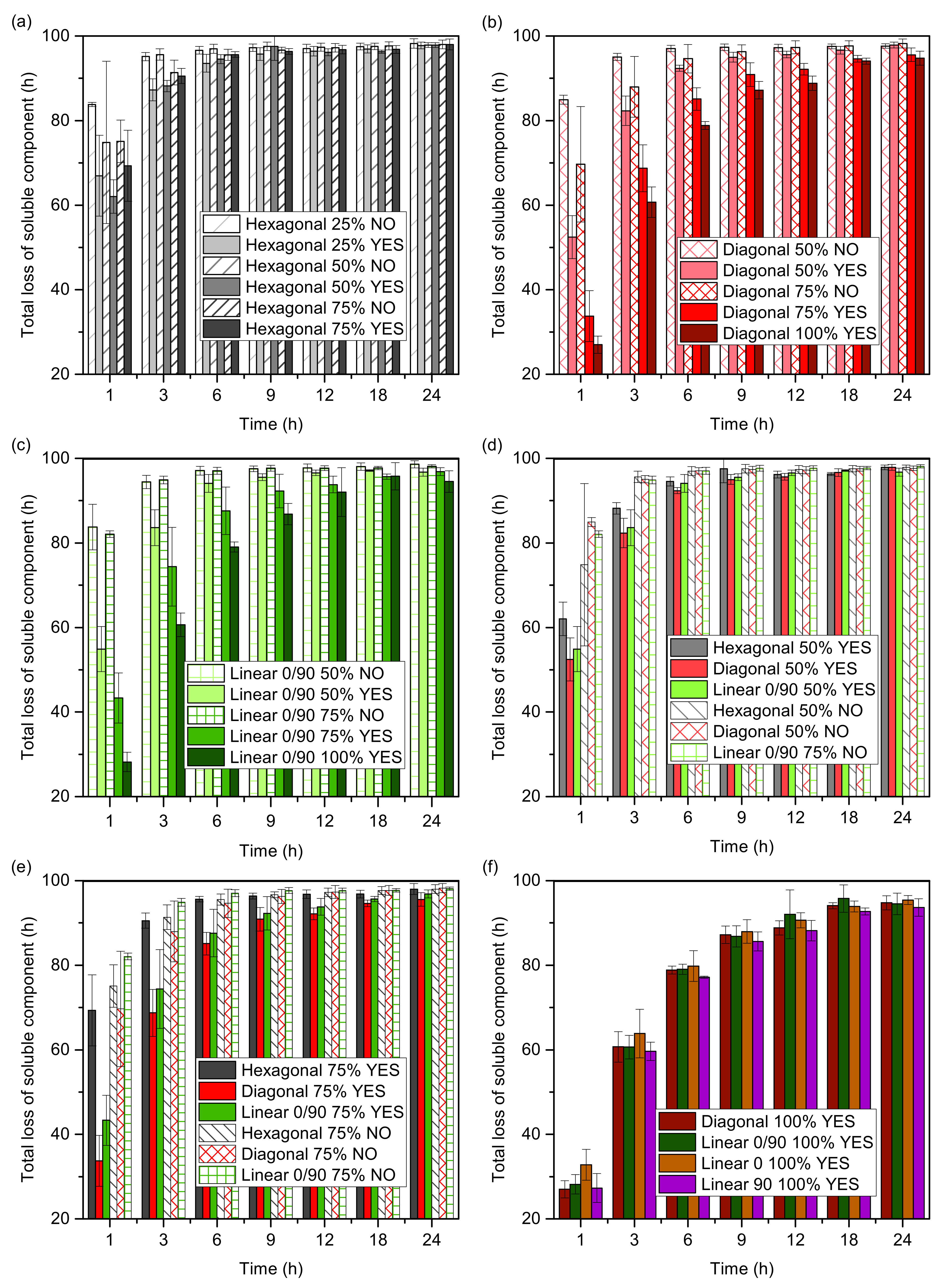
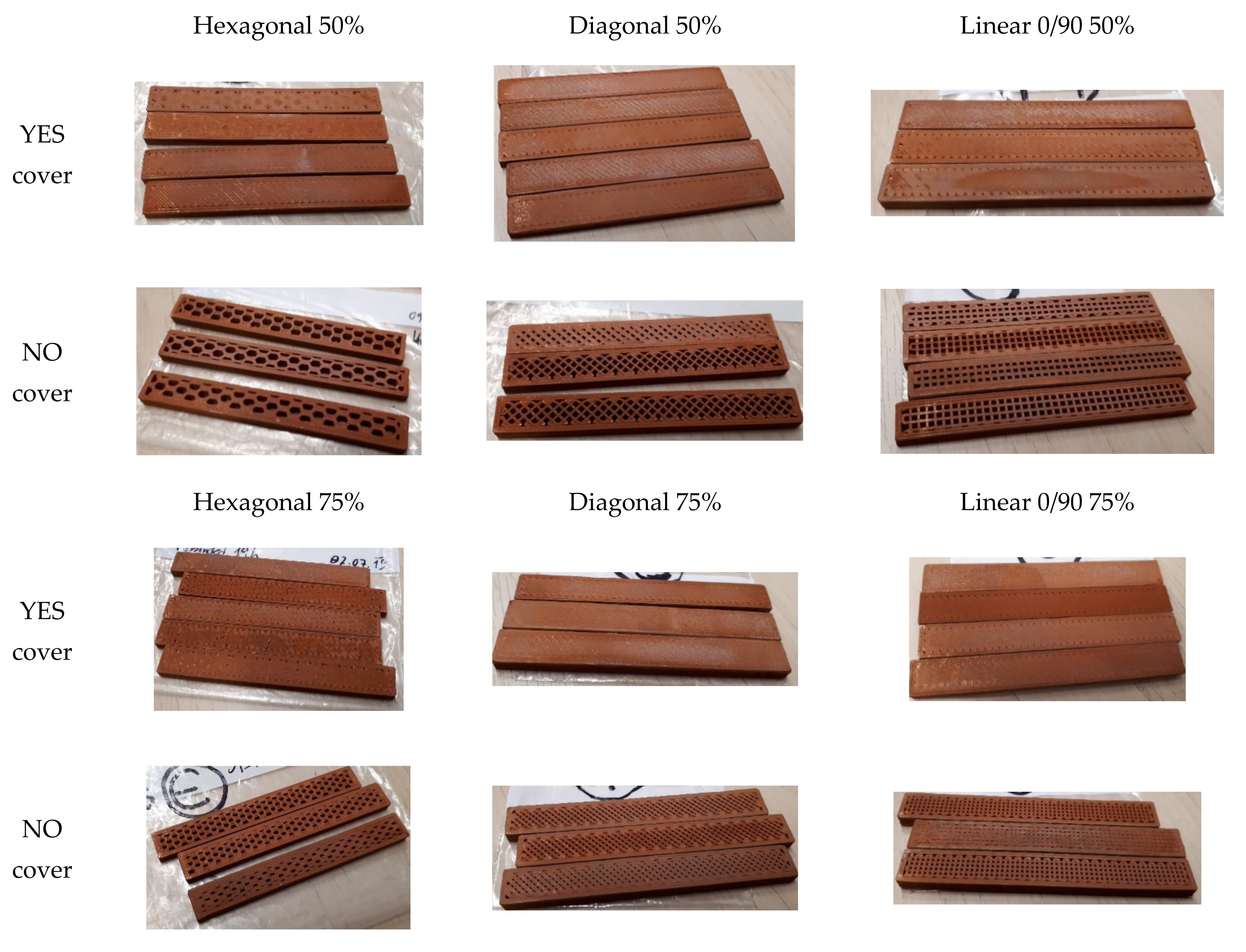
3.1. 3D Printing and Solvent Debinding

It was possible to print six specimens for all the series reliably. Examples of the printed specimens with the three infill patterns (hexagonal, diagonal, and linear) at a 50% infill degree are shown in Figure 4a. The layer thickness was almost constant (the first layer was set to be twice as large as the other layers to fit the required thickness), as shown by the optical microscopy image in Figure 4b.
Putting a cover on specimens significantly decreases the debinding rate in all the cases, as seen by the big difference in the loss of soluble component between specimens with and without cover during the first hours in the solvent (Figure 5). The specimens without cover can reach a debinding plateau between 3 and 6 h in the solvent. In contrast, specimens with covers reach a debinding plateau between 6 and 12 h, depending on the infill grade. Adding a cover decreases the debinding rate because of the reduction of the exposed surface of the specimens, as demonstrated in several studies for powder injection moulded parts [65,66,67,68,69]. For specimens without cover, the outer surface and the surface of the infill structure are in direct contact with the solvent and most of the binder is removed in the initial steps of debinding.
On the other hand, only the sides and covers are in direct contact with the solvent for specimens with covers at the beginning of the immersion. For these specimens, the solvent must go through the cover to reach the infill structure and later, the dissolved polymer must diffuse through the cover to be evacuated from the specimens. Therefore, the cover increases the diffusion distance, which slows down the debinding process, resulting in the trend observed in Figure 5.
The only difference in the debinding rate of the specimens with different infill geometry is the higher debinding rate for the hexagonal specimens with cover compared to the diagonal and linear specimens with cover, as observed in the initial hours for the specimens with a 50% infill (Figure 5d), and especially for the specimens with a 75% infill (Figure 5e). Defects in the cover of the specimens Hexagonal 50% YES and Hexagonal 75% YES (Figure 6) are responsible for the different debinding rates. In specimens with a hexagonal infill geometry, the unsupported cover between infill structures is larger than for diagonal and linear specimens (Figure 6), which results in more unsupported material that deformed during printing, creating pores in the middle of the cover and not just only at the junction between the perimeter and the infill. During solvent debinding, the solvent can easily penetrate the specimens through these porous defects, which are also used to diffuse the dissolved polymer molecules more quickly.
No effect of the infill grade on the debinding rate can be observed for the specimens without cover. For specimens with covers, the debinding rate decreases with increasing infill grade. The debinding plateau is reached after 9 h in the solvent for the specimens with an infill higher than 75% (Figure 5). Moreover, during the first hours in the solvent, the loss of soluble binder is significantly lower for the diagonal specimens with cover and higher infill grade (Figure 5b) and for Linear 0/90 100% YES compared to Linear 0/90 75% YES (Figure 5c). In the specimens with a higher infill grade, a higher fraction of material is not in direct contact with the solvent at the beginning of the immersion; thus, the diffusion path is longer, as previously described, resulting in a lower debinding rate. However, the infill grade does not influence the debinding rate of the hexagonal specimens with cover, and at certain debinding times, the opposite trend can be observed (Figure 5a). The origin of these results for the hexagonal specimens is the defects caused by the large, unsupported distance, as shown in Figure 6 and discussed in the previous paragraph.

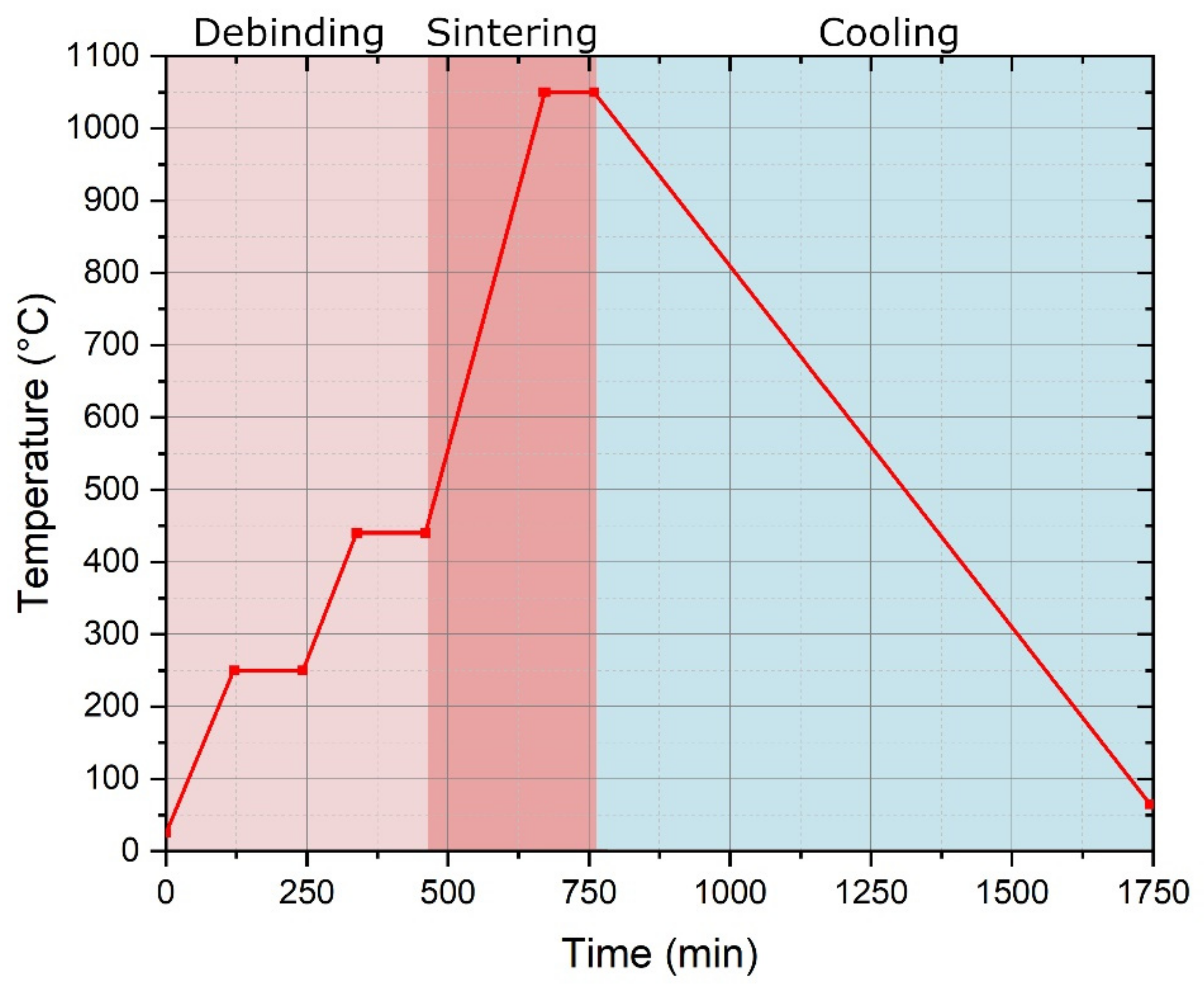
3.2. Thermal Debinding and Sintering

A previous study by the authors [70] reported that the shaped copper specimens did not survive the sintering regime since the heating rate of 5 K/min from room temperature up to 1050 °C did not allow for the decomposition of the backbone component before sintering occurred. Using fast heating rates led to the complete loss of shape since the binder melted before it decomposed. Therefore, in this study, thermal debinding was performed at 2 K/min between room temperature and 250 °C, and between 250 and 450 °C. The profile included two plateaus of 1 h at 250 and 450 °C (Figure 3) to allow for the gradual removal of any residual main binder component and the insoluble backbone component. Finally, a 1 h plateau at 1050 °C was used to sinter and densify the specimens. It was possible to obtain specimens without defects, such as bloating or blistering, using this longer thermal debinding cycle. The mass loss from green to sintered parts was in the range of 7.89 to 8.19 wt.% (average and standard deviation of 7.95 ± 0.04 wt.%), with no dependence on the infill geometry or the presence of cover. Examples of sintered specimens are shown in Figure 7.
Defects were observed on the specimens having a cover and low infill density (25 and 50%); since the bridges were not adequately supported during printing, debinding and sintering, the material slumped into the cavity due to gravity. These defects could be observed already after solvent debinding but were especially pronounced after thermal debinding and sintering. Figure 7a–c show that the cover defects were minimized as the infill increases since the infill could better support shorter bridges. The specimens with a 25% and 50% infill had material dips and roughness in the sections where no material was present underneath (Figure 7a,b). Specimens with a 75% infill had a smoother surface, but the larger bridging distance for the Hexagonal 75% YES specimens than for the Diagonal 75% YES or the Linear 0/90 75% YES specimens resulted in the rough surface discussed in the previous section.
Another defect observed after the sintering of the specimens is the delamination between the infill structure and the perimeter, especially for the specimens with a lower infill degree (Figure 7a,d). Moreover, specimens with a hexagonal infill, and especially specimens with a 0/90 infill, had more pronounced delamination than specimens with a diagonal infill, in which the zones in contact between the perimeter and the infill were larger and prevented the delamination (as can be observed in Figure 7). The delamination between the perimeter and infill is a common defect in parts produced by MEX [27]. It can be solved by programming a defined overlap between the perimeter and the infill structure when slicing the parts [35]. No overlap adjustments were considered in this study to determine the bonding between the perimeter and the infill.
During the sintering, specimens shrank considerably (Figure 7d) after the particles fused, and the porosity of the parts was reduced. The shrinkage of the various specimens was recorded in length (longest dimension), width (intermediate dimension), and height (shortest dimension). The shrinkage after sintering for the different types of specimens is shown in Figure 8. The highest shrinkage occurred in the length and width, while the height had the lowest shrinkage. The largest significant differences in shrinkage were observed for the specimens with 100% infill degree. For instance, the shrinkage in length was significantly lower than the shrinkage in width for Linear 90 100% YES and Linear 0/90 100% YES specimens (Figure 8d). While in series Linear 0 100% YES, the shrinkage in length was significantly higher than the shrinkage in width (Figure 8d).
The anisotropic shrinkage of series Linear 0 100% YES and Linear 90 100% YES indicates that the shrinkage is dominant in the deposition direction. In series Linear 0 100% YES, the strands are deposited along the length, and in Linear 90 100% YES, the strands are deposited along the width; therefore, the maximum shrinkage occurred in length and width, respectively. For series Linear 0/90 100% YES, the number of strands deposited along the width is higher than the number of strands deposited along the length; thus, these specimens shrunk more in width than in length. An infill pattern with alternating deposition along the length and width in each layer can create a more isotropic shrinkage as observed for series Diagonal 100% YES, where the shrinkage in length and width is not significantly different. These shrinkage results are crucial, and they must be considered when designing the 3D model in CAD software by oversizing the dimensions by the respective percentages to match the tolerances required.
Anisotropic shrinkage is not unique for specimens prepared by MEX, and it has been observed for sintered specimens prepared by different shaping mechanisms, such as tape casting and MIM. During all these shaping processes, particles orient in the direction of flow. The copper particles used in this investigation are not entirely round, as shown in Figure 1b; therefore, the ellipsoidal particles present in the powder rotate so that their longest axis is parallel to the flow direction. Moreover, it has been shown that ellipsoid particles shrink more in the long axis because larger necks form rapidly in the contact area along the short axis since less material is required to close the inter-particle pores [71]. Sintering theory and simulations have shown that the shrinkage rate is inversely proportional to the square of the neck size; thus, large necks shrink more slowly [72]. As such, more shrinkage can be expected in the direction of deposition during MEX. Please note that the shrinkage would also depend on the sintering conditions, such as the sintering time and temperature, increasing the final density of the parts and modifying their microstructure.

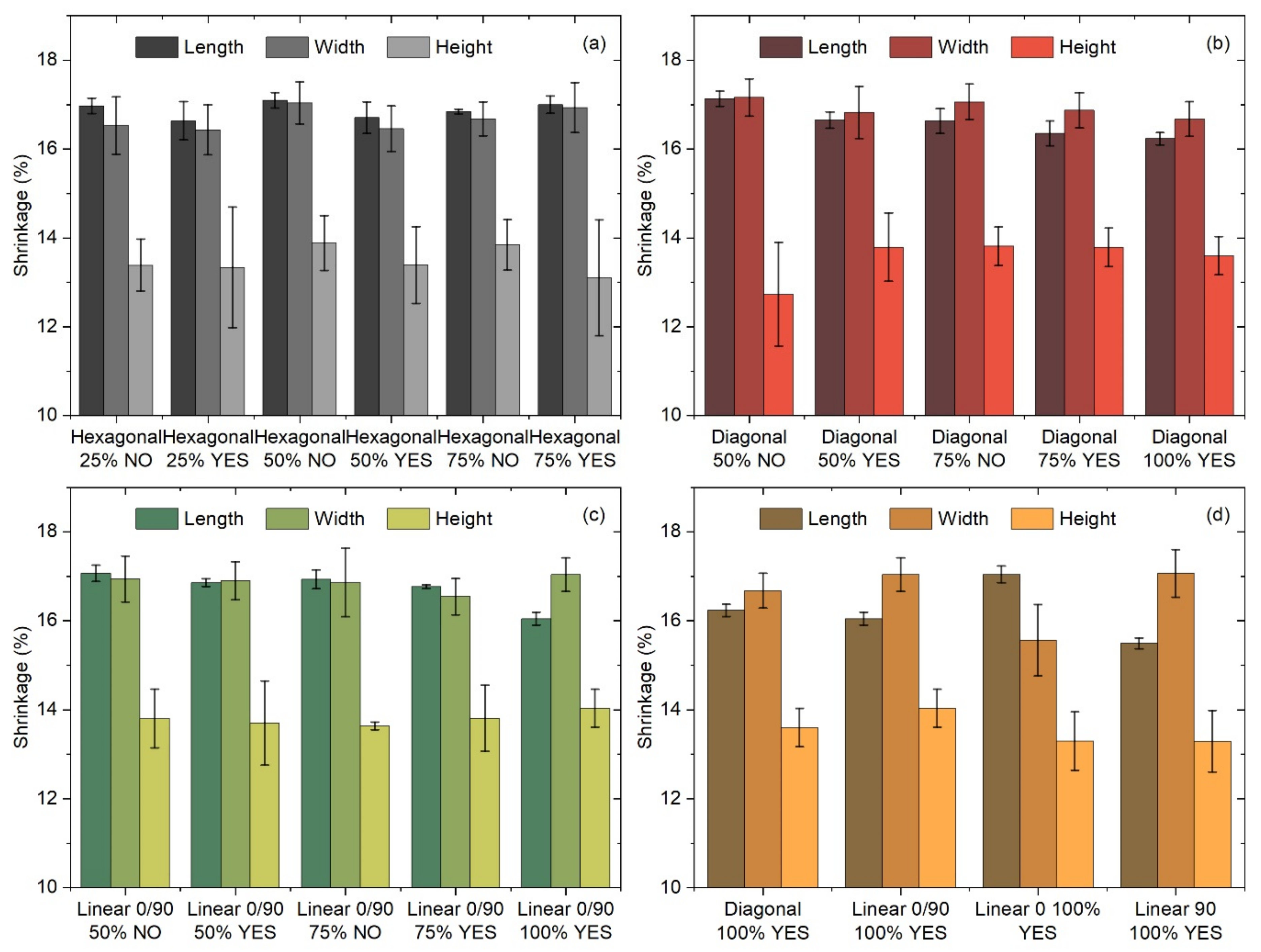
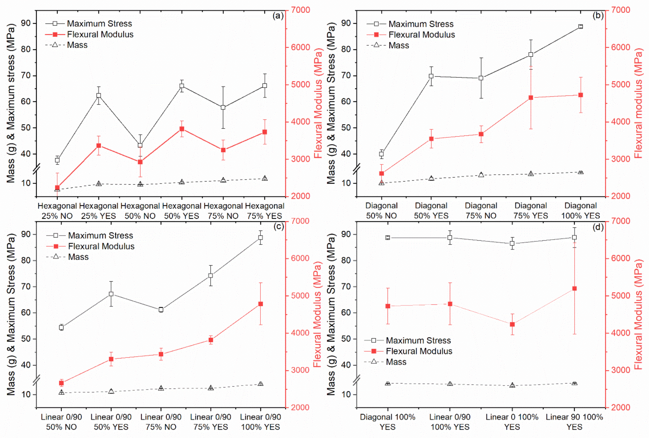
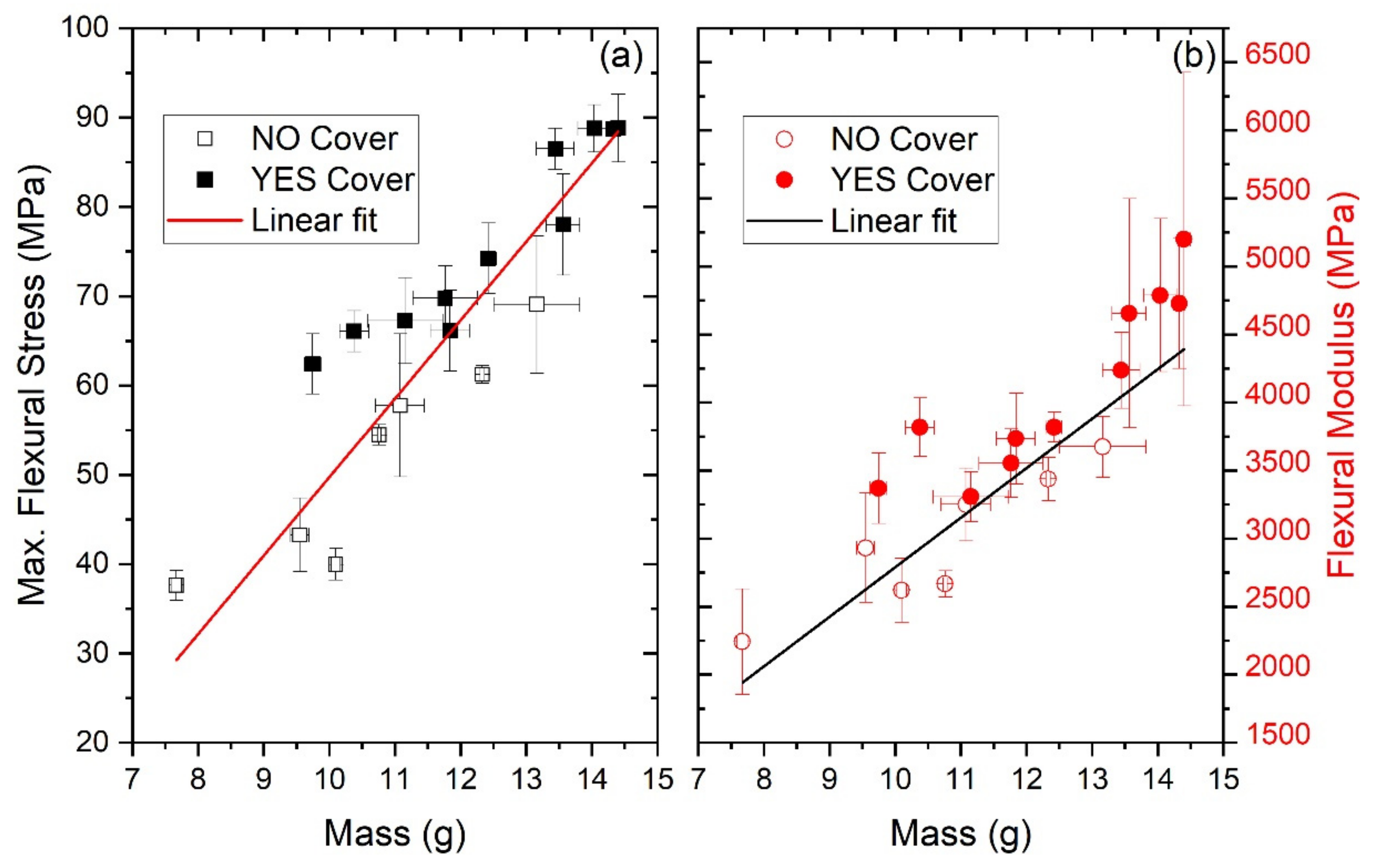
3.3. Properties of Sintered Specimens

After sintering, the mass and the bending properties of at least three specimens per infill pattern and infill degree were measured. The masses of the sintered specimens are shown in Figure 9 to demonstrate how the infill degree and covers affect the mass of specimens. As expected, adding a cover and increasing the infill degree of the specimens increased the mass of the specimens. It can be said that increasing the mass of the specimens increased the maximum flexural stress and flexural modulus. The addition of a cover profoundly increased the flexural properties of sintered specimens, particularly those with a low infill degree. It had a more pronounced effect than increasing the infill density for specific specimens, agreeing with Steiner’s Theorem.
For specimens with a 25% hexagonal infill, the maximum stress and flexural modulus increased 166% and 150%, respectively, when adding a cover. When the infill was increased to 50%, adding a cover still increased the stress and modulus, this time by 153% and 130%, respectively. Finally, adding a cover to specimens with a 75% hexagonal infill led to non-significantly different values (Figure 9a). Similar results are observed for specimens with a 50% diagonal infill, where adding a cover increases the maximum stress by 175% and the modulus by 136%. However, adding a cover to specimens with a 75% diagonal infill leads to non-significantly different values (Figure 9b). A slightly different trend was observed when the infill was linear 0/90. In this case (Figure 9c), adding a cover to specimens with a 50% infill increases the maximum stress by 123% and the modulus by 124%; for specimens with a 75% infill degree, adding a cover increases the maximum stress by 121% and modulus by 111%. When comparing specimens with a 100% infill with various patterns, it can be seen in Figure 9d that the mass, maximum stress and flexural modulus are non-significantly different from each other.
The results presented in Figure 9 are beneficial when designing lightweight parts. For example, the same bending response was obtained using specimens weighing 9.75 ± 0.13 g, 10.38 ± 0.22 g or 11.84 ± 0.30 g with a hexagonal infill pattern and a cover (Figure 9a). The same bending response was also obtained for specimens weighing 11.77 ± 0.49 g, with a 50% diagonal infill and a cover or specimens weighing 13.16 ± 0.66 g with a 75% diagonal infill and no cover (Figure 9b). The best absolute bending properties can be obtained by producing specimens with an infill degree of 100%. Nevertheless, the presented results demonstrate the advantages of MEX since hollow specimens with a cover cannot be manufactured by traditional forming or subtractive manufacturing techniques. It would also be challenging to produce fully enclosed hollow parts with PBF or BJT since the loose powder is trapped inside the specimens unless a draining orifice is designed in the part.
As previously mentioned, increasing the mass of a specimen generally increases the flexural strength and modulus of specimens (Figure 9). This behaviour can be better observed in Figure 10, where the maximum stress and the flexural modulus increase linearly as the mass increases. However, using a cover (NO Cover and YES Cover) produces outliers to the left of these linear functions fitting the data, indicating that many specimens with a cover have a lower weight and yet the same level of maximum stress or flexural modulus, following Steiner’s Theorem, which is also often used in carbon fibre reinforced sandwich structures. Therefore, producing parts with a cover is a reasonable strategy to achieve lightweight specimens by MEX.

4. Conclusions

A new feedstock material for material extrusion consisting of pure copper particles and a thermoplastic binder has been developed. Filaments with this feedstock were produced, and numerous bending specimens with different infill patterns and infill degrees were also produced. Variants of the bending specimens were fabricated with covers on the top and bottom to create semi-hollow specimens. After the parts were fabricated, they were immersed in cyclohexane to remove the thermoplastic binder partially. It was observed that the infill density and the presence of covers significantly affect the debinding rates of specimens. Specimens without covers and lower infill densities reached equilibrium after 9 h, while specimens with covers needed 12 or 18 h depending on their infill grade. A sintering regime with a 2 K/min heating rate and 1 h plateaus at 250, 450 and 1050 °C were needed to remove the remaining binder components and obtain copper parts without losing the printed shape. It was observed that the flexural properties of the specimens increased almost linearly with the mass of the specimens. However, specimens with covers could have lower masses than specimens without covers and similar flexural properties. These results indicate that MEX followed by debinding and sintering can be utilized to fabricate lightweight specimens made of pure copper, which would be impossible to produce by pure subtractive manufacturing techniques and immensely challenging using powder-based AM technologies.

Author Contributions

Conceptualization, J.G.-G.; methodology, S.C., J.V.E., M.K. and F.A.; software, J.V.E.; validation, J.G.-G., S.C. and F.A.; formal analysis, J.G.-G., S.C.; investigation, J.G.-G., S.C. and J.V.E.; resources, J.V.E., C.K., F.A., M.K. and C.H.; data curation, J.G.-G. and S.C.; writing—original draft preparation, J.G.-G.; writing—review and editing, J.G.-G., S.C., J.V.E., M.K., F.A., C.K., C.H.; visualization, J.G.-G. and S.C.; supervision, C.K.; project administration, J.G.-G., M.K. and C.H.; funding acquisition, J.G.-G., M.K., C.K. and C.H. All authors have read and agreed to the published version of the manuscript.

Funding

This research was funded by the Austrian Research Promotion Agency (FFG), project 3DMulti-Mat, project number 875650. MDPI waived the APC for the editorial services of J.G.-G.

Institutional Review Board Statement

Not applicable.

Informed Consent Statement

Not applicable.

Data Availability Statement

Data is contained within the article.

Conflicts of Interest

The authors declare no conflict of interest. The funders had no role in the design of the study, in the collection, analyses, or interpretation of data, in the writing of the manuscript, or in the decision to publish the results.

References

  1. Gibson, I.; Rosen, D.; Stucker, B. Additive Manufacturing Technologies: 3D Printing, Rapid Prototyping, and Direct Digital Manufacturing, 2nd ed.; Springer: New York, NY, USA, 2015; ISBN 978-1-4939-2113-3. [Google Scholar]
  2. Wohlers, T.; Campbell, I.; Diegel, O.; Kowen, J.; Caffrey, T. Wohlers Report 2017: 3D Printing and Additive Manufacturing State of the Industry: Annual Worldwide Progress Report; Wohlers Associates, Inc.: Fort Collins, CO, USA, 2017; ISBN 978-0-9913332-3-3. [Google Scholar]
  3. Körner, C. Additive manufacturing of metallic components by selective electron beam melting—A review. Int. Mater. Rev. 2016, 61, 361–377. [Google Scholar] [CrossRef] [Green Version]
  4. Warnes, S.L.; Little, Z.R.; Keevil, C.W. Human coronavirus 229E remains infectious on common touch surface materials. MBio 2015, 6, e01697-15. [Google Scholar] [CrossRef] [Green Version]
  5. Scully, J. Editorial-THE COVID-19 pandemic, part 1: Can antimicrobial copper-based alloys help suppress infectious transmission of viruses originating from human contact with high-touch surfaces? Corrosion 2020, 76, 523–527. [Google Scholar] [CrossRef]
  6. Dai, D.; Gu, D. Thermal behavior and densification mechanism during selective laser melting of copper matrix composites: Simulation and experiments. Mater. Des. 2014, 55, 482–491. [Google Scholar] [CrossRef]
  7. Tran, T.Q.; Chinnappan, A.; Lee, J.K.Y.; Loc, N.H.; Tran, L.T.; Wang, G.; Kumar, V.V.; Jayathilaka, W.A.D.M.; Ji, D.; Doddamani, M.; et al. 3D printing of highly pure copper. Metals 2019, 9, 756. [Google Scholar] [CrossRef] [Green Version]
  8. Bogue, R. Lasers in manufacturing: A review of technologies and applications. Assem. Autom. 2015, 35, 161–165. [Google Scholar] [CrossRef]
  9. Lykov, P.A.; Safonov, E.V.; Akhmedianov, A.M. Selective laser melting of copper. Mater. Sci. Forum 2016, 843, 284–288. [Google Scholar] [CrossRef]
  10. Horn, T.J.; Gamzina, D. Additive manufacturing of copper and copper alloys. In ASM Handbook; Bourell, D.L., Frazier, W.E., Kuhn, H.A., Seifi, M., Eds.; ASM International: Materials Park, OH, USA, 2020; pp. 388–418. ISBN 978-1-62708-290-7. [Google Scholar]
  11. Gonzalez-Gutierrez, J. Indirect additive manufacturing techniques for metal parts: Binder-based additive manufacturing techniques. In Reference Module in Materials Science and Materials Engineering; Elsevier: Amsterdam, The Netherlands, 2021. [Google Scholar] [CrossRef]
  12. Badrinarayan, B.; Barlow, J.W. Selective laser sintering of a Copper-PMMA system. In Solid Freeform Fabrication Symposium; Annual International Solid Freeform Fabrication Symposium: Austin, TX, USA, 1991; pp. 245–250. [Google Scholar]
  13. Klassen, A.; Bauereiß, A.; Körner, C. Modelling of electron beam absorption in complex geometries. J. Phys. D Appl. Phys. 2014, 47, 65307. [Google Scholar] [CrossRef]
  14. Lodes, M.A.; Guschlbauer, R.; Körner, C. Process development for the manufacturing of 99.94% pure copper via selective electron beam melting. Mater. Lett. 2015, 143, 298–301. [Google Scholar] [CrossRef]
  15. Gonzalez-Gutierrez, J.; Cano, S.; Schuschnigg, S.; Kukla, C.; Sapkota, J.; Holzer, C. Additive manufacturing of metallic and ceramic components by the material extrusion of highly-filled polymers: A review and future perspectives. Materials 2018, 11, 840. [Google Scholar] [CrossRef] [PubMed] [Green Version]
  16. Bai, Y.; Williams, C.B. An exploration of binder jetting of copper. Rapid Prototyp. J. 2015, 21, 177–185. [Google Scholar] [CrossRef] [Green Version]
  17. Bai, Y.; Wagner, G.; Williams, C.B. Effect of particle size distribution on powder packing and sintering in binder jetting additive manufacturing of metals. J. Manuf. Sci. Eng. 2017, 139. [Google Scholar] [CrossRef] [Green Version]
  18. Institute for Rare Earths and Metals AG. Ultrafine Copper Powder-Prices and Manufacture. Available online: https://en.institut-seltene-erden.de/ultrafeines-kupferpulver-preise-und-herstellung/ (accessed on 20 May 2021).
  19. Munsch, M.; Schmidt-Lehr, M.; Wycisk, E. Metal Additive Manufacturing with Sinter-Based Technologies; AM Power Insights No. 4, Hamburg, Germany. 2018. Available online: https://am-power.de/en/insights/additive-manufacturing-sinter-based-technologies/ (accessed on 23 April 2020).
  20. Ligon, S.C.; Liska, R.; Stampfl, J.; Gurr, M.; Mülhaupt, R. Polymers for 3D printing and customized additive manufacturing. Chem. Rev. 2017, 117, 10212–10290. [Google Scholar] [CrossRef] [PubMed] [Green Version]
  21. Brenken, B.; Barocio, E.; Favaloro, A.; Kunc, V.; Pipes, R.B. Fused filament fabrication of fiber-reinforced polymers: A review. Addit. Manuf. 2018, 21, 1–16. [Google Scholar] [CrossRef]
  22. Gibson, M.A.; Mykulowycz, N.M.; Shim, J.; Fontana, R.R.; Schmitt, P.; Roberts, A.; Ketkaew, J.; Shao, L.; Chen, W.; Bordeenithikasem, P.; et al. 3D printing metals like thermoplastics: Fused filament fabrication of metallic glasses. Mater. Today 2018, 21, 697–702. [Google Scholar] [CrossRef]
  23. Wu, G.; Langrana, N.A.; Sadanji, R.; Danforth, S.C. Solid freeform fabrication of metal components using fused deposition of metals. Mater. Des. 2002, 23, 97–105. [Google Scholar] [CrossRef]
  24. Bose, A.; Schuh, C.A.; Tobia, J.C.; Tuncer, N.; Mykulowycz, N.M.; Preston, A.; Barbati, A.C.; Kernan, B.; Gibson, M.A.; Krause, D.; et al. Traditional and additive manufacturing of a new Tungsten heavy alloy alternative. Int. J. Refract. Met. Hard Mater. 2018, 73, 22–28. [Google Scholar] [CrossRef]
  25. Gonzalez-Gutierrez, J.; Arbeiter, F.; Schlauf, T.; Kukla, C.; Holzer, C. Tensile properties of sintered 17-4PH stainless steel fabricated by material extrusion additive manufacturing. Mater. Lett. 2019, 248, 165–168. [Google Scholar] [CrossRef]
  26. Thompson, Y.; Gonzalez-Gutierrez, J.; Kukla, C.; Felfer, P. Fused filament fabrication, debinding and sintering as a low cost additive manufacturing method of 316L stainless steel. Addit. Manuf. 2019, 30, 100861. [Google Scholar] [CrossRef]
  27. Damon, J.; Dietrich, S.; Gorantla, S.; Popp, U.; Okolo, B.; Schulze, V. Process porosity and mechanical performance of fused filament fabricated 316L stainless steel. Rapid Prototyp. J. 2019, 27, 1319–1327. [Google Scholar] [CrossRef]
  28. Singh, P.; Shaikh, Q.; Balla, V.K.; Atre, S.V.; Kate, K.H. Estimating powder-polymer material properties used in design for metal fused filament fabrication (DfMF3). JOM 2019, 11, 840. [Google Scholar] [CrossRef]
  29. Naranjo, J.A.; Berges, C.; Gallego, A.; Herranz, G. A novel printable high-speed steel filament: Towards the solution for wear-resistant customized tools by AM alternative. J. Mater. Res. Techol. 2021, 25, 185. [Google Scholar] [CrossRef]
  30. Wagner, M.A.; Sebastian, T.; Clemens, F.; Wheeler, J.M.; Rusch, A.; Ganz, R.; Spolenak, R. Feedstock development for fused deposition of 316L stainless steel and characterization of final materials properties. In Euro PM2020, Proceedings of the EuroPM 2020, Virtual Congress, Online, 5–7 October 2020; European Powder Metallurgy Association, Ed.; European Powder Metallurgy Association (EMPA): Chantilly, France, 2020; ISBN 9781899072538. [Google Scholar]
  31. Dehdari Ebrahimi, N.; Ju, Y.S. Thermal conductivity of sintered copper samples prepared using 3D printing-compatible polymer composite filaments. Addit. Manuf. 2018, 24, 479–485. [Google Scholar] [CrossRef] [Green Version]
  32. Cano, S.; Gonzalez-Gutierrez, J.; Sapkota, J.; Spoerk, M.; Arbeiter, F.; Schuschnigg, S.; Holzer, C.; Kukla, C. Additive manufacturing of zirconia parts by fused filament fabrication and solvent debinding: Selection of binder formulation. Addit. Manuf. 2019, 26, 117–128. [Google Scholar] [CrossRef]
  33. Gorjan, L.; Reiff, L.; Liersch, A.; Clemens, F. Ethylene-vinyl acetate as a binder for additive manufacturing of tricalcium phosphate bio-ceramics. Ceram. Inter. 2018, 44, 15817–15823. [Google Scholar] [CrossRef]
  34. Nötzel, D.; Eickhoff, R.; Hanemann, T. Fused filament fabrication of small ceramic components. Materials 2018, 11, 1463. [Google Scholar] [CrossRef] [PubMed] [Green Version]
  35. Cano, S.; Lube, T.; Huber, P.; Gallego, A.; Naranjo, J.A.; Berges, C.; Schuschnigg, S.; Herranz, G.; Kukla, C.; Holzer, C.; et al. Influence of the infill orientation on the properties of zirconia parts produced by fused filament fabrication. Materials 2020, 13, 3158. [Google Scholar] [CrossRef] [PubMed]
  36. Conzelmann, N.A.; Gorjan, L.; Sarraf, F.; Poulikakos, L.D.; Partl, M.N.; Müller, C.R.; Clemens, F.J. Manufacturing complex Al 2 O 3 ceramic structures using consumer-grade fused deposition modelling printers. Rapid Prototyp. J. 2020, 26, 1035–1048. [Google Scholar] [CrossRef]
  37. Nötzel, D.; Hanemann, T. New feedstock system for fused filament fabrication of sintered alumina parts. Materials 2020, 13, 4461. [Google Scholar] [CrossRef] [PubMed]
  38. Orlovská, M.; Chlup, Z.; Bača, Ľ.; Janek, M.; Kitzmantel, M. Fracture and mechanical properties of lightweight alumina ceramics prepared by fused filament fabrication. J. Eur. Ceram. Soc. 2020, 40, 4837–4843. [Google Scholar] [CrossRef]
  39. Veteška, P.; Hajdúchová, Z.; Feranc, J.; Tomanová, K.; Milde, J.; Kritikos, M.; Bača, Ľ.; Janek, M. Novel composite filament usable in low-cost 3D printers for fabrication of complex ceramic shapes. Appl. Mater. Today 2021, 22, 100949. [Google Scholar] [CrossRef]
  40. Lengauer, W.; Duretek, I.; Fürst, M.; Schwarz, V.; Gonzalez-Gutierrez, J.; Schuschnigg, S.; Kukla, C.; Kitzmantel, M.; Neubauer, E.; Lieberwirth, C.; et al. Fabrication and properties of extrusion-based 3D-printed hardmetal and cermet components. Int. J. Refract. Met. Hard Mater. 2019, 82, 141–149. [Google Scholar] [CrossRef]
  41. Berger, C.; Abel, J.; Pötschke, J.; Moritz, T. Properties of additive manufactured hardmetal components produced by fused filament fabrication (FFF). In Proceedings of the Euro PM2018, Bilbao, Spain, 14–18 October 2018; EPMA, Ed.; European Powder Metallurgy Association (EMPA): Shrewsbury, UK, 2018; ISBN 978-1-899072-50-7. [Google Scholar]
  42. Coelho, S.; Magro, A.; Texeira, P.; Ferreira, N.; Pereira, P.; Rodrigues, F.; Jorge, H.; Sacramento, J. Development of formulations of WC-Co filament for Fused Filament Fabrication. In Euro PM2020 Proceedings of the EuroPM 2020, Virtual Congress, Online, 5–7 October 2020; European Powder Metallurgy Association, Ed.; European Powder Metallurgy Association (EMPA): Chantilly, France, 2020; ISBN 9781899072538. [Google Scholar]
  43. Kukla, C.; Cano, S.; Kaylani, D.; Schuschnigg, S.; Holzer, C.; Gonzalez-Gutierrez, J. Debinding behaviour of feedstock for material extrusion additive manufacturing of zirconia. Powder Met. 2019, 62, 196–204. [Google Scholar] [CrossRef]
  44. Rosnitschek, T.; Glamsch, J.; Lange, C.; Alber-Laukant, B.; Rieg, F. An Automated open-source approach for debinding simulation in metal extrusion additive manufacturing. Designs 2021, 5, 2. [Google Scholar] [CrossRef]
  45. Lieberwirth, C.; Harder, A.; Seitz, H. Extrusion based additive manufacturing of metal parts. J. Mech. Eng. Autom. 2017, 7. [Google Scholar] [CrossRef] [Green Version]
  46. Singh, G.; Missiaen, J.-M.; Bouvard, D.; Chaix, J.-M. Copper extrusion 3D printing using metal injection moulding feedstock: Analysis of process parameters for green density and surface roughness optimization. Addit. Manuf. 2021, 38, 101778. [Google Scholar] [CrossRef]
  47. de Calan, G. Benchmark of AM Technologies; Nanoe Webinar: Ballainvilliers, France, 2020; Available online: https://nanoe.com/ (accessed on 12 May 2020).
  48. Gonzalez-Gutierrez, J.; Thompson, Y.; Handl, D.; Cano, S.; Schuschnigg, S.; Felfer, P.; Kukla, C.; Holzer, C.; Burkhardt, C. Powder content in powder extrusion moulding of tool steel: Dimensional stability, shrinkage and hardness. Mater. Lett. 2021, 283, 128909. [Google Scholar] [CrossRef]
  49. Abel, J.; Scheithauer, U.; Janics, T.; Hampel, S.; Cano, S.; Müller-Köhn, A.; Günther, A.; Kukla, C.; Moritz, T. Fused filament fabrication (FFF) of metal-ceramic components. JoVE 2019. [Google Scholar] [CrossRef] [Green Version]
  50. Kukla, C.; Cano, S.; Moritz, T.; Müller-Köhn, A.; Courtney, P.; Hampel, S.; Holzer, C. Multimaterial Components by Material Extrusion-Fused Filament Fabrication (ME-FFF)-Production of an Infrared Heater. Ceram. Forum Int. 2019, 96, 22–27. [Google Scholar]
  51. Ultrafuse 316L-User Guidelines for 3D Printing Metal Parts. Available online: https://www.mholland.com/media/BASF_Ultrafuse_316L_User_Guidelines.pdf (accessed on 5 July 2021).
  52. Galati, M.; Minetola, P. Analysis of density, roughness, and accuracy of the atomic diffusion additive manufacturing (ADAM) Process for metal parts. Materials 2019, 12, 4122. [Google Scholar] [CrossRef] [Green Version]
  53. Gloeckle, C.; Konkol, T.; Jacobs, O.; Limberg, W.; Ebel, T.; Handge, U.A. Processing of highly filled polymer–metal feedstocks for fused filament fabrication and the production of metallic implants. Materials 2020, 13, 4413. [Google Scholar] [CrossRef] [PubMed]
  54. Mireles, J.; Espalin, D.; Roberson, D.; Zinniel, B.; Medina, F.R.; Wicker, R.B. Fused deposition modeling of metals. In Proceedings of the Solid Freeform Fabrication Symposium, Austin, TX, USA, 6–8 August 2012; Laboratory for Freeform Fabrication, the University of Texas at Austin: Austin, TX, USA, 2012; pp. 836–845. [Google Scholar]
  55. Riecker, S.; Hein, S.B.; Studnitzky, T.; Andersen, O.; Kieback, B. 3D printing of metal parts by means of fused filament fabrication—A Non Beam-Based Approach. In Euro PM2017, Proceedings of the Euro PM2017 Congress & Exhibition, Milan, Italy, 1–5 October 2017; EPMA, Ed.; European Powder Metallurgy Association (EMPA): Bellstone, UK, 2017; ISBN 978-1-899072-49-1. [Google Scholar]
  56. Singh, P.; Balla, V.K.; Gokce, A.; Atre, S.V.; Kate, K.H. Additive manufacturing of Ti-6Al-4V alloy by metal fused filament fabrication (MF3): Producing parts comparable to that of metal injection molding. Prog. Addit. Manuf. 2021, 11, 840. [Google Scholar] [CrossRef]
  57. Tosto, C.; Tirillò, J.; Sarasini, F.; Cicala, G. Hybrid metal/polymer filaments for fused filament fabrication (FFF) to print metal parts. Appl. Sci. 2021, 11, 1444. [Google Scholar] [CrossRef]
  58. Zhang, Y.; Bai, S.; Riede, M.; Garratt, E.; Roch, A. A comprehensive study on Fused Filament Fabrication of Ti-6Al-4V structures. Addit. Manuf. 2020, 101256. [Google Scholar] [CrossRef]
  59. Gorjan, L.; Galusca, C.; Marwah, S.; Sebastian, T.; Clemens, F. Effect of stearic acid on rheological properties and printability of ethylene-vinyl acetate-based feedstocks for fused filament fabrication of alumina. Addit. Manuf. 2020, 101391. [Google Scholar] [CrossRef]
  60. Eickenscheidt, M.; Langenmair, M.; Dbouk, A.; Nötzel, D.; Hanemann, T.; Stieglitz, T. 3D-printed hermetic alumina housings. Materials 2021, 14, 200. [Google Scholar] [CrossRef] [PubMed]
  61. Fan, N.C.; Chen, Y.Y.; Wei, W.C.J.; Liu, B.H.; Wang, A.B.; Luo, R.C. Porous Al2O3 catalyst carrier by 3D additive manufacturing for syngas reforming. J. Ceram. Process. Res. 2017, 18, 676–682. [Google Scholar]
  62. Cano, S.; Cajner, H.; Gonzalez-Gutierrez, J.; Sapkota, J.; Kukla, C.; Arbeiter, F.; Schuschnigg, S.; Holzer, C. Optimization of material properties for highly-filled thermoplastic polymers used in fused filament fabrication of ceramics. AIP Conf. Proc. 2019, 2065. [Google Scholar] [CrossRef]
  63. Sadaf, M.; Bragaglia, M.; Nanni, F. A simple route for additive manufacturing of 316L stainless steel via Fused Filament Fabrication. J. Manuf. Process. 2021, 67, 141–150. [Google Scholar] [CrossRef]
  64. Li, T.; Gonzalez-Gutierrez, J.; Raguž, I.; Holzer, C.; Li, M.; Cheng, P.; Kitzmantel, M.; Shi, L.; Huang, L. Material extrusion additively manufactured alumina monolithic structures to improve the efficiency of plasma-catalytic oxidation of toluene. Addit. Manuf. 2021, 37, 101700. [Google Scholar] [CrossRef]
  65. Kim, S.W.; Lee, H.-W.; Song, H.; Kim, B.H. Pore structure evolution during solvent extraction and wicking. Ceram. Int. 1996, 22, 7–14. [Google Scholar] [CrossRef]
  66. Westcot, E.J.; Binet Andrandall, C.; German, R.M. In situ dimensional change, mass loss and mechanisms for solvent debinding of powder injection moulded components. Powder Metall. 2003, 46, 61–67. [Google Scholar] [CrossRef]
  67. Rolere, S.; Soupremanien, U.; Bohnke, M.; Dalmasso, M.; Delafosse, C.; Laucournet, R. New insights on the porous network created during solvent debinding of powder injection-molded (PIM) parts, and its influence on the thermal debinding efficiency. J. Mater. Process. Technol. 2021, 24, 117163. [Google Scholar] [CrossRef]
  68. Shivashankar, T.S.; German, R.M. Effective length scale for predicting solvent-debinding times of components produced by powder injection molding. J. Am. Ceram. Soc. 1999, 82, 1146–1152. [Google Scholar] [CrossRef]
  69. Oliveira, R.V.B.; Soldi, V.; Fredel, M.C.; Pires, A.T.N. Ceramic injection moulding: Influence of specimen dimensions and temperature on solvent debinding kinetics. J. Mater. Process. Technol. 2005, 160, 213–220. [Google Scholar] [CrossRef]
  70. Ecker, J.V.; Dobrezberger, K.; Gonzalez-Gutierrez, J.; Spoerk, M.; Gierl-Mayer, C.; Danninger, H. Additive manufacturing of steel and copper using fused layer modelling: Material and process development. Powder Metall. Progr. 2019, 19, 63–81. [Google Scholar] [CrossRef]
  71. Zavaliangos, A.; Missiaen, J.M.; Bouvard, D. Anisotropy in shrinkage during sintering. Sci. Sinter. 2006, 38, 13–25. [Google Scholar] [CrossRef]
  72. Tikare, V.; Braginsky, M.; Olevsky, E.; Johnson, D.L. Numerical simulation of anisotropic shrinkage in a 2D compact of elongated particles. J. Am. Ceram. Soc. 2005, 88, 59–65. [Google Scholar] [CrossRef]
Figure 1. (a) Particle size distribution measured by laser scattering and (b) shape of copper powder observed by scanning electron microscopy.
Applsci 11 07262 g001
Figure 2. Temperature profile of compounder used to prepare copper feedstock.
Applsci 11 07262 g002
Figure 3. Thermal debinding and sintering profile. All heating rates were 2 K/min. 1 h debinding plateaus at 250 and 450 °C and 1 h sintering plateau at 1050 °C were used.
Applsci 11 07262 g003
Figure 4. (a) Examples of bending specimens with three infill patterns at 50% infill degree (left to right: hexagonal, diagonal and linear 0/90) and (b) side view of a printed specimen showing the deposited layers.
Applsci 11 07262 g004
Figure 5. Debinding rate of printed specimens with different infill patterns and infill grades (a) hexagonal, (b) diagonal 45/45, and (c) linear 0/90, as well as different infill patterns but same infill grade, (d) 50%, (e) 75% and (f) 100%.
Applsci 11 07262 g005
Figure 6. Comparison between bending specimens with the same infill grade and different infill pattern with and without cover.
Applsci 11 07262 g006
Figure 7. Sintered specimens with cover and without and different infill degree (a) 25%, (b) 50%, and (c) 75%. (d) Comparison between sintered and printed part. The dotted rectangle highlights the delamination between the infill and the perimeter.
Applsci 11 07262 g007
Figure 8. Shrinkage for the various specimens with different infill patterns and infill degrees (a) hexagonal 25 to 75%, (b) diagonal 50 to 100%, (c) linear 0/90 50 to 100%, and (d) 100% diagonal and lineal at different angles.
Applsci 11 07262 g008
Figure 9. Average maximum flexural stress, flexural modulus and mass for sintered specimens with different infill patterns: (a) Hexagonal, (b) diagonal 45/45, (c) linear 0/90 and (d) 100% filled with 4 different patterns.
Applsci 11 07262 g009
Figure 10. (a) Maximum flexural stress and (b) flexural modulus as a function of specimen mass for copper specimens with and without covers.
Applsci 11 07262 g010
Table 1. List of the various specimen characteristics.
Infill PatternDegree of Infill (%)Cover Layer (Yes/No)Short Notation
Hexagonal25NoHexagonal 25% NO
Hexagonal25YesHexagonal 25% YES
Hexagonal50NoHexagonal 50% NO
Hexagonal50YesHexagonal 50% YES
Hexagonal75NoHexagonal 75% NO
Hexagonal75YesHexagonal 75% YES
Diagonal (±45°)50NoDiagonal 50% NO
Diagonal (±45°)50YesDiagonal 50% YES
Diagonal (±45°)75NoDiagonal 75% NO
Diagonal (±45°)75YesDiagonal 75% YES
Diagonal (±45°)100YesDiagonal 100% YES
Linear (0°/90°)50NoLinear 0/90 50% NO
Linear (0°/90°)50YesLinear 0/90 50% YES
Linear (0°/90°)75NoLinear 0/90 75% NO
Linear (0°/90°)75YesLinear 0/90 75% YES
Linear (0°/90°)100YesLinear 0/90 100% YES
Linear (0°)100YesLinear 0 100% YES
Linear (90°)100YesLinear 90 100% YES
Publisher’s Note: MDPI stays neutral with regard to jurisdictional claims in published maps and institutional affiliations.

