Abstract
Effective data interoperability and schedule analysis play a significant role in improving the management of prefabricated buildings. However, there is a lack of efficient strategies and comprehensive approaches for data interoperability and data-based automated schedule analysis. This paper intends to promote prefabricated buildings’ management by solving these two problems via developing an IFC-based framework consisting of three parts. Firstly, this framework proposed a mechanism to establish an IFC-based 4D construction management information model of prefabricated buildings. Furthermore, a non-relational database—graph database—is introduced to twin this model into a task-centered network to realize the interoperation of construction information among different participants. Finally, graph database-based strategies to update data, automatically analyze construction schedules and visualize the 4D construction management information model are described. The proposed framework is validated in a prefabricated engineering case. In this case, an IFC-based and graph database-based 4D construction management information model is established through IFC standard’s extension. The graph database-based analysis of the model automatically recognizes the engineering case’s critical path information, delay analysis information, and schedule network analysis information. It is illustrated that this framework can successfully establish a unified IFC-based information model of prefabricated buildings’ construction management to prompt effective data interoperability. In addition, the application of this IFC-based information model in graph database can automatically analyze the construction schedules to prevent possible delays in advance. In short, the significance of this paper is to innovatively propose an IFC-based and graph data-based information model to solve the difficulties of ineffective data interoperation and unautomated schedule analysis in prefabricated buildings’ construction management. This study can be the digital foundation of further IFC-based digital twin.
1. Introduction
In recent years, prefabricated buildings have rapidly developed due to their low cost [1], high industrialization [2], and environment-friendly [3] characteristics, which are contrary to the traditional cast-in-situ constructions’ inefficiency and waste of resources [4]. Moreover, research demonstrates the energy-saving potential of prefabrication based on life cycle analysis and thermal performance evaluation [5]. For instance, research proposes a method to design energy-efficient precast wall that can reach a high level of thermal behavior and indoor comfort in cold climate [6]. In the construction field, prefabrication is regarded as the first level of industrialization [7]. However, the level of informatization of prefabricated buildings’ construction management does not match the level of industrialization of their production.
Simultaneously, BIM (Building Information Modeling) [8] technology gains significant development in construction management, and it is regarded as the solution of prefabricated buildings’ construction management. Since many different disciplines, participants, and BIM software are involved in prefabricated buildings’ construction management [9], managers have to work with different types of file formats, which leads to difficulty in data sharing. Research shows that information sharing among all participants and processes is the most critical factor required to manage prefabricated construction [10].
In general, the issues related to data sharing in BIM projects are mostly solved with a standardized file exchange format, i.e., Industry Foundation Classes (IFC). As the primary data standard of BIM, the IFC standard published by buildingSMART plays a significant role in sharing data [11]. The latest official version of the IFC standard is IFC4 ADD2TC1(ISO 16739-1:2018) [12], which is used in this paper. Although the IFC standard is widely applied in various scenarios, obvious shortcomings in the field of construction management’s interoperability and schedule analysis still exist.
Firstly, there is no extension of prefabricated buildings’ construction management in the current IFC schema, making it challenging to share completed construction management information [13]. Secondly, IFC files are hard to timely modify, update, and interoperate [14]. Thirdly, most data mining techniques lack the capability to handle IFC directly [15]. Finally, the applications to show a dynamic 4D presentation and visualize the extended schedule analysis information of IFC-based information model are not available. In conclusion, an integrally efficient framework that can help to store, update, analyze and visualize construction management information is essential for prefabricated buildings.
Therefore, this paper intends to promote prefabricated buildings’ management by developing an IFC-based framework consisting of three parts. Firstly, this framework proposes a mechanism to establish an IFC-based 4D construction management information model of prefabricated buildings with the extension of the construction schedule analysis information, which includes schedule network analysis information and delay analysis information. Furthermore, a non-relational database—graph database—is introduced to twin a task-centered network of the IFC-based 4D information model to realize the interoperation of construction information among different participants. The last part of this framework is graph database-based strategies to update data, analyze the construction schedule and visualize the 4D information model.
The content of this paper is organized as follows. In Section 2, a concise literature review summarizes the 4D BIM technology, delay analysis, and IFC extension in state of the art. Section 3 is the introduction to the proposed framework of prefabricated buildings’ construction management. Section 4 is the first part of the framework in which an IFC-based extension schema of the construction management information model is given, and an IFC-based 4D construction management information model of the prefabricated building is established through this template. Section 5 is the second part of the framework in which an approach to twinning the IFC-based 4D construction management information model into a non-relation database is proposed. This section also lays the foundation of the following analysis. In Section 6, workflow to analyze the construction schedules and visualize the information model is described when the IFC-based 4D construction management information model is twinned into the graph database. In Section 7, the feasibility and rationality of the proposed framework are studied through a case study.
2. Literature Review
2.1. 4D BIM and Construction Management
The 4D BIM construction technology increases the dimension of time based on the 3D model [16] so that the entire construction process can be expressed dynamically and thus be more intuitive. The 4D theory was first proposed by Stanford University in 1996, and the CIFE 4D-CAD system was developed on this basis [17]. Jianping Zhang’s team proposed an extended 4D construction management model [18]. This model takes WBS as the core and combines construction management elements such as schedule planning and resource management to visualize the construction process. In 2012, a 4D Site Management Model (4DSMM) [19] was further proposed by this team. 4DSMM links 3D models with specific schedules to generate 4D models of site management. Additionally, Chen [20] used the 4D BIM model coupled with the quality information model to implement the project’s construction quality control. De Soto [21] also used a tabu-search algorithm and 4D models to improve the construction project schedule.
Although using 4D BIM in the management of prefabricated buildings is beneficial, 4D BIM cannot be cultivated with incomplete, untimely data exchange and lacking real-time visibility [22]. Firstly, forming the 4D BIM models relies on specific BIM software [23]. It means information is inaccessible once being separated from this particular software. Additionally, the 4D BIM is mainly focused on on-site construction management. Prefabricated buildings have a lot of off-site construction information, which has difficulties in interoperating among different stakeholders, phases, and BIM software [24]. Once specific details of one model are modified, other models cannot update the information timely. This is disadvantageous for the highly dynamic construction process of prefabricated buildings. In summary, the lack of information interoperation between BIM software keeps the management of prefabricated buildings inefficient and locked-in to tool vendors [25]. Unlike the methods of 4D BIM and construction management in this literature, this paper adopts the standard for sharing data in the whole process of engineering projects—IFC standards—as the basis for modeling the 4D management information model of prefabricated building. By establishing IFC-based information model and by combining it with the innovative graph database technology proposed in this paper, the problem of ineffective data interoperability can be solved.
2.2. Delay Analysis of Construction Management
Off-site prefabrication and transportation are also reasons for construction delay, which is a primary barrier to adopting prefabricated construction [26]. The monitoring and management of prefabricated buildings’ construction processes are widely considered to have strategic importance in responding to the building industry’s dynamics [27]. Delay analysis is a method that determines whether delays caused by a party in individual activities result in a delay in total project duration [28]. There are many methods to analyze the delays of construction processes. Researchers [29] pointed out that the Critical Path Method (CPM) is the most frequently used method to plan and control the construction execution process. The CPM method facilitates the analysis of delays in (1) supporting the computation of project duration, shortest path, and critical path [30] and (2) analyzing the delayed activities’ impact on the duration [31]. However, the CPM also has shortcomings. Firstly, identification of deviation occurs too late because schedules are often updated monthly [32]. Moreover, Turkakin [33] also concluded that schedule updates are often not performed. The critical path method cannot be executed in analysis and critical path changes cannot be considered [34]. Additionally, deviations are not clearly visualized [35]. Finally, in the actual projects, we find that drawing the construction network plan diagram and calculating the parameters in the CPM rely on the manual way, which makes it not convenient for the applicants in actual projects. It is worth noting that the current CPM lacks the capability to handle IFC directly. Yet, the method of schedule analysis based on the IFC and graph database proposed in this paper can calculate the IFC models’ information and is entirely different from the current CPM. After twinning the IFC-based 4D construction management information model into the task-centered network, the graph database-based data update will solve the problem of lagging data updates in the current CPM. In addition, the graph-based critical path mining algorithm will automatically calculate CPM parameters and delayed tasks’ parameters, which is different from the currently manual calculation. In addition, the analysis of task-centered networks based on graph theory and network analysis methods can recognize schedule network analysis information, which is impossible by the current CPM method. In summary, the IFC-based and graph database-based schedule analysis methods are automated and can further improve the management of prefabricated buildings.
2.3. IFC Extension
The IFC standard was widely studied and applied when it launched. Yu [36] established the FMC (Facilities Management Classes) data description standard for construction equipment management based on the IFC standard. Lam [37] used IFC for energy consumption analysis and realized a data mapping engine between the building model and the energy analysis model. Zhang [38,39] committed to the research and development of IFC-based intelligent facilities management systems and an IFC-based graphic information model for virtual construction. Ma [40] succeeded in establishing static information models of building energy consumption based on IFC. Xu [41] innovatively developed a Public-Private Partnership (PPP) project performance evaluation model based on IFC. The IFC standard has been used in all aspects of the construction industry. Moreover, many scholars extended the IFC standard in terms of construction management information. Akinci [42] proposed extending the IFC framework and integrating the project model of completion and design information to achieve automatic completion conditions assessment. Seo [43] proposed an IFC extended model that can store plan information. Park et al. [44] proposed a visualization method supported by web and database technology to realize the visualization of daily 4D BIM.
In general, the IFC standard has good scalability, whereas currently, the IFC standard only supports a limited number of engineering cases in actual projects, especially in prefabricated building construction. One difficulty in popularizing and applying IFC extension models is that there is seldom appropriated software to visualize IFC-based 4D information models. The functions and characteristics of common IFC software are shown in Table 1. For example, common open-source 3D BIM software, such as XBIMXplore, IFC++, and Bim Vision, perform an excellent 3D display of IFC files, but do not support visualizing time-related entities. In other words, the extended information in the IFC model can only be presented statically in the existing papers, but in this paper, the information associated with the task in the extended IFC-based 4D construction management information model is presented dynamically through the framework based on IFC and graph database. This will facilitate the managers to grasp the construction information dynamically and prevent possible failure in advance.

Table 1.
Software for parsing IFC files and their features.
2.4. Conclusion
Through literature reviews, we found that the existing research achievements cannot well resolve the following issues of 4D construction management. Firstly, the prefabricated buildings’ construction management information cannot be integrated into a unified information model. Secondly, the unified information model based on IFC is difficult to interoperate among various phases and participants in the construction of prefabricated buildings. Finally, effective methods to automatically carry out delay analysis and dynamic presentation of construction information are essential to prefabricated buildings’ construction management. Therefore, this paper proposes the IFC-based 4D construction management framework to promote the prefabricated building’s construction management by achieving the construction information’s interoperability and enhance the managers’ control of the construction process by automated analyzing construction schedules.
3. Methodology
This paper develops a framework consisting of three parts to realize the interoperability and automated analysis of prefabricated buildings’ construction management information, as Figure 1 shows. In this figure, we can explicitly find the framework is divided into four layers, namely, Data Acquisition Layer, Realization Layer, Interoperability Layer, and Analysis Layer. Data Acquisition Layer gleans fabrication information, transport information, hoisting information, and installation information of construction process. The Realization Layer realizes an IFC-based 4D construction management information model of prefabricated buildings. After twinning the obtained information model into the graph database, the Interoperability Layer is the platform for data interoperation. The Analysis Layer is based on the IFC and graph database and has the function of data update, schedule network analysis, delay analysis and 4D visualization.
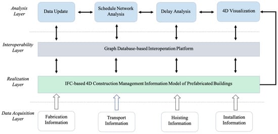
Figure 1.
Framework overview.
Firstly, this framework realizes an IFC-based 4D construction management information model of prefabricated buildings. Through this part, the construction management information needed in the construction process is integrated into a unified information model, and thus lays the foundation for the information management of prefabricated buildings’ construction process. The establishing procedure is divided into two steps. The first step is extending the IFC schema. An integrated prefabricated buildings’ construction management information model is established in this step, including task information and related component information, resource information, cost information, and schedule analysis information. The second step is to instantiate the template one-by-one according to the obtained construction information to complete the IFC-based 4D construction management information model of prefabricated buildings. The detailed creation process is shown in Section 4.
Furthermore, this framework twins the obtained IFC-based 4D construction management information model into the graph database. Through this part, the IFC-based construction management information model can be well interoperated among different participants and facilitates the construction analysis in the following part at the same time. The information model obtained in the previous parts of the framework is based on the IFC standard, which has high structural complexity and low data density [45]. These features lead the IFC-based information model to have difficulties in reading, retrieve, and interoperation. This framework introduces a non-relationship database—graph database—to solve the problem; first, by formulating the mapping rules and twin the IFC-based construction management into a task-centered network. In this network, all the relationships between tasks, resources, costs, components, and schedule analysis information can be obtained and used, making the IFC-based information retrieved and read easily. Secondly, all the participants can operate the database to update the construction information. This information will be transmitted to other participants timely, making the interoperation among stakeholders and different construction stages efficient. Finally, IFC files are outputted from the graph database by traversing the graph database’s information, thus achieving the round-tripping between the graph database-based information network and the IFC-based 4D information model. The detailed creation mechanism is shown in Section 5.
The last part of this framework is strategies to analyze the graph database-based information model. Through this part, the framework based on IFC realizes the data update, automatic analysis, and dynamic display of construction data, which will significantly benefit the synergistic and reduce the manual work on construction analysis. The data update is mainly about the project participants to update the actual construction data in the graph database for other participants to search and analyze. Construction schedule analysis includes schedule network analysis and delay analysis. Schedule network analysis means calculating the schedule networks’ parameters and storing them in the extended IFC schema. Delay analysis means calculating the critical information in the whole prefabricated project, feeding back on project delays, and storing schedule changes in extended IFC schema to assist decision-makers. The 4D model is then introduced to help project participants understand the progress of the project more intuitively. The 4D model information will be extracted into Microsoft Project and Navisworks through the graph database’s powerful retrieve capabilities. The detailed realization mechanism can be seen in Section 6.
4. Realization of IFC-Based 4D Construction Information Model of Prefabricated Buildings
This section is the first part of the framework and gives the method to extend the IFC schema to store 4D construction management information. In this section, IFC standard and its extension mechanism is first introduced in Section 4.1. According to the three main extension mechanisms, the extended schema of process information model, resources information model, cost information model, and schedule analysis information model are illustrated in Section 4.2. Section 4.3 describes the instantiation process of the IFC-based 4D construction management information model of prefabricated buildings in detail.
4.1. IFC Standard and Its Extension Mechanism
The IFC standard’s data schema is divided into four conceptual layers, from bottom to top: resource layer, core layer, interop layer, and domain layer. The quotation of information between the various layers in the IFC schema complies with strict regulations that the next layer prohibits reference to the upper layer’s information. Therefore, when the IFC standard needs to be extended, it is only necessary to add information to the upper structure of the IFC standard, and new categories can be created by quoting the data from the lower layer by the upper layer without changing the overall schema of the IFC standard.
There are three main extension mechanisms [46]: The first one is to increase the IFC entity types [47]; the second method is to instantiate IfcProxy, IfcBuildingElement [48]; the third method is to increase the property sets. A comparison of the three extension methods is shown in Table 2. The three methods have their advantages and disadvantages and are suitable for different application needs. The method based on increasing entity types has the highest operational efficiency and consumes the most time. Therefore, for choosing the extension methods of the IFC-based 4D construction management models of prefabricated buildings, this paper will avoid increasing entity types, which means that the extension process in this paper should use IfcProxy, IfcBuildingElement, and property sets more.
Table 2.
Comparison of three extension methods.
4.2. Realizing the Extension of IFC-Based 4D Construction Management Information Model of Prefabricated Buildings
Much construction management information will be obtained outside the construction site for highly industrialized characteristics of prefabricated buildings. To dynamically manage the construction information, a framework is proposed in this paper to establish an IFC-based construction management information model of prefabricated buildings. Furthermore, since all components are discretized during the prefabricated building construction process and can only correspond to one task simultaneously, this information model will center on IfcTask. In realizing the IFC-based information model’s extension, this article will center on the IfcTask entities and associate all the related process information, resource information, cost information, component information, and construction schedule analysis information.
4.2.1. Realizing Process Information’s Extension Based on IFC Standard
This part is to realize process information’s extension based on IFC standard. In the IFC standard, the entity IfcProcess (an abstract IFC entity) and its subtypes and the corresponding relationship entities are used to describe the project’s process. Figure 2 illustrates how to extend the schema of the construction process information model. Firstly, IfcTask is a subtype entity of IfcProcess, used to describe specific tasks in the construction process, and the entity IfcRelSequence is used to describe the sequence of these tasks. Furthermore, IfcTask can establish a hierarchical relationship with each other through the entity IfcRelNests. In addition, The IfcRelAssignsToControl relationship is used to assign controls in the IFC model to related objects to establish a one-to-many relationship between the general schedule and IfcTask. General schedule is described by the IfcControl entity. The IfcControl has two subtypes, namely, IfcWorkPlan and IfcWorkSchedule. The IfcWorkPlan entity can describe project plan information and the IfcWorkSchedule entity can describe various schedule information. The IfcRelDeclares relationship is used to process the declaration of the objects or attributes of the project so that this entity can be used to describe the relationship between the construction project (IfcProject) and the project plans (IfcWorkPlan, IfcWorkSchedule).
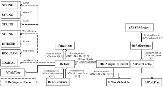
Figure 2.
Process information’s extension model.
4.2.2. Realizing Resource Information’s Extension Based on IFC Standard
This part is to realize resource information’s extension based on IFC standard. Figure 3 illustrates how to extend the schema of the construction resources information model. Firstly, using the entity IfcResource and its subtype IfcConstructionResource to describe resource information. Specifically, IfcConstructionEquipmentResource, IfcConstructionMaterialResource, IfcConstructionProductResource, IfcSubContractEquipmentResource, IfcLaborResource, and IfcCrewResource are used to describe equipment resources, material resources, product resources, subcontracted equipment resources, labor resources, and crew resources, respectively. What is more, IfcConstructionEquipmentResource, the entity representing equipment resources, can be associated with IfcTransportElement, IfcDiscreteAccessory, and IfcProxy to represent equipment information more detailed. IfcConstructionMaterialResource represents the entity of material resources, which can be associated with the entity IfcQuantityWeight to express the required resources’ weight information. Following this logic can extend the IFC resource information model.
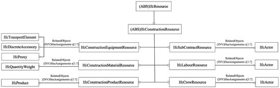
Figure 3.
Resource information’s extension model.
4.2.3. Realizing Cost Information’s Extension Based on IFC Standard
This part is to realize cost information’s extension based on IFC standard. Figure 4 illustrates how to extend the schema of the construction cost information model. Firstly, in the IFC standard, the entity IfcCostItem is used to describe the cost items. Then, IfcCostItem is related with the entity IfcApplied Value through the entity IfcRelAssociatesAppliedValue, which is used to describe the association between cost items, resources, and cost values. The application entity IfcAppliedValue is used to capture the value used for the formula calculation. Finally, the cost entity IfcCostValue is used to define a monetary amount or the value that affects a monetary amount. The entity IfcAppliedValueRelationship is used to describe the algorithmic association between cost and value, such as construction cost equal to the sum of labor cost, material cost, and mechanical cost. Therefore, the cost information of the IFC information model can be formed. Therefore, the extended schema to describe the resource information is completed.
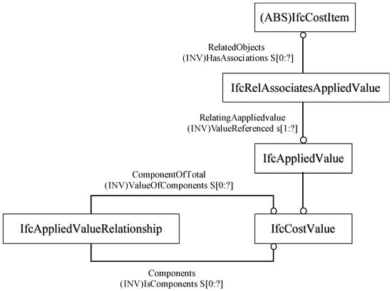
Figure 4.
Cost information’s extension model.
4.2.4. Realizing Construction Schedule Analysis Information’s Extension Based on IFC Standard
As stated previously, the IFC4 ADD2TC1(ISO 16739-1:2018) does not provide predefined entities to represent construction schedule analysis’s results. Hence, realizing schedule analysis information’s extension based on the IFC standard is necessary. To achieve the objective of realizing the information model centered on IfcTask, this paper will introduce IfcPropertySet to describe the analysis information and associate it with IfcTask. Therefore, IfcPropertySet is determined by three categories, including Pset_ScheduleNetworkAnalysis, Pset_CriticalPath, and Pset_DelayAnalysis, as shown in Table 3.
Table 3.
Definition of the delay analysis property set.
The Pset_ScheduleNetworkAnalysis is used to store results of the schedule network analysis. Schedule network analysis results are composed of three parameters: degree centrality, closeness centrality, and betweenness centrality, which are explained in detail in Section 6. Therefore, this property set contains three properties, namely _IfcDegreeCentrality, _IfcClosenessCentrality, and _IfcBetweennessCentrality, as shown in Table 4.
Table 4.
Definition of the Pset_ ScheduleNetworkAnalysis.
The Pset_CriticalPath is used to store information of the critical path. This IfcPropertySet contains two properties to describe the critical path’s information, namely _IfcCriticalPath and _IfcCriticalPathDate, as shown in Table 5. The _IfcCriticalPath’s data type is IfcBoolean. The _IfcCriticalPath uses a Boolean representing whether the activity resides on the critical path of the project. Furthermore, the _IfcCriticalPathDate’s data type is IfcDateTime. This property is extended to record when the critical path is made since the critical path may be changed.
Table 5.
Definition of the Pset_CriticalPath.
The Pset_DelayAnalysis is used to store information of delay. This IfcPropertySet contains nine properties to describe the delay events information, as shown in Table 6.
Table 6.
Definition of the Pset_DelayAnalysis.
Finally, Figure 5 illustrates how to extend the schema of the schedule analysis information model. In this figure we can see that all the IfcProperty is related to the corresponding IfcPropertySet. Then, all the IfcPropertySet is associated with IfcTask by IfcRelDefinesByProperties.
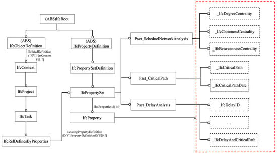
Figure 5.
Schedule analysis information’s extension model.
4.2.5. Realizing Information Extension Based on IFC Standard
Based on the above steps, the relevant IFC-based 4D construction management information model is extended. This model takes the IfcTask as its mainline and relates to the relevant components, resource information, cost information, schedule network analysis, and delay analysis information. The extended IFC-based information model provides essential technical support to realize the interoperation of construction information, data update, schedule network analysis, delay analysis, and 4D visualization simulation. Figure 6 illustrates the completed schema of the construction information model based on the IFC standard. Specifically, in this figure we can find that the relationship entity IfcRelAssignsToProduct associates IfcTask with the components related to the construction process. The relationship entity IfcRelAssignsToProcess associates IfcTask with the resource information and cost information related to the construction process. The relationship entity IfcRelDefinesByProperties associates IfcTask with the schedule network analysis information and delay analysis information related to the construction process. Therefore, the extended schema to describe the construction management information of prefabricated buildings is completed.
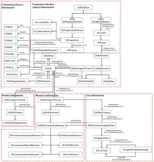
Figure 6.
The IFC-based 4D construction management information model.
4.3. Instantiating the IFC-Based 4D Construction Management Information Model of Prefabricated Buildings
This part will use the xBIM [49] Nuget package under the Visual Studio platform to instantiate the IFC-based 4D construction management information model of prefabricated buildings. According to the schema created in the previous step, the flowchart to implement the IFC-based 4D construction information is shown in Figure 7. This figure shows the four steps to modify an original IFC file into the IFC-based 4D construction management information model. The four steps are process information creation, resource information creation, resources information creation, and construction analysis information creation, which are corresponding to the information extension schema.
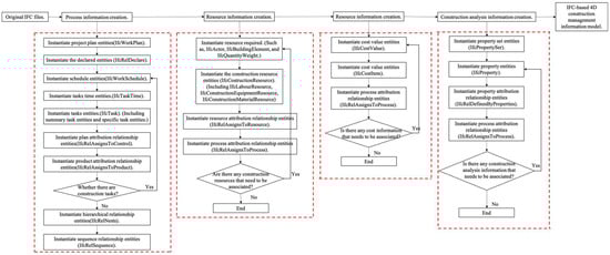
Figure 7.
Flow chart of instantiating construction management information.
Through instantiating entities corresponding to process information, resource information, cost information, schedule network analysis information, delay analysis information of prefabricated buildings, a complete IFC-based 4D construction management information model of prefabricated buildings is created. The prefabricated buildings’ construction process is divided into components prefabrication, components transportation, components hoisting, and components installation in the information model. Therefore, these four parts correspond to four summary job tasks, namely: TaskFabricateSummary, TaskTransportSummary, TaskHoistSummary, and TaskInstallSummary; these four summary job tasks according to the types of components could be further subdivided for specific purposes. The summary task TaskFabricateSummary is subdivided into prefabricating slabs, walls, and roofs, respectively named TaskFabricateSlabSummary, TaskFabricateWallSummary, TaskFabricateRoofSummary, and others of the same kind. Then, these summary tasks at this level are further subdivided into tasks corresponding to specific components. The rest of the summary tasks and specific tasks can be deduced by analogy. Each specific task is associated with process information, resource information, cost information, and construction schedule analysis information and forming a complete IFC-based 4D construction information model of prefabricated buildings.
5. Twinning the IFC-Based 4D Construction Management Information Model into Graph Database
The IFC-based 4D construction information model of prefabricated buildings is established in Section 4, but the features of the IFC standard require a further operation of this information model. This section is the second part of the framework and twins the IFC-based 4D construction management information model into graph database. One feature of the IFC standard is that the reference relationship between the entities in the IFC-based information model is complicated, leading to the poor readability of the IFC files. Furthermore, the IFC files obtained in the previous step are hard to modify, update, and interoperate timely. Especially in the process of prefabricated building construction, many participants have the requirements to operate and exchange the data through IFC files. Thus, an automatic algorithm to parse and twin IFC files is necessary to reveal the IFC files complicated inner relationships in an intuitive graph and increase data interoperability for further management requests. This part is also the foundation of the following automated construction schedule analysis whose realization depends on the graph-based algorithm.
The reasons to use graph database to store and twin the IFC-based information model are as follows. Firstly, the graph database is more suitable than the relational database to store the IFC information model. Solihin [50] transformed BIM data into an open relational database to make the BIM data accessible for wide ranges of query capabilities. Marmo [51] mapped the IFC schema into a relational database to support performance assessment and maintenance management. However, IFC schema is often large, such as IFC 4 × 2 with 816 different entity types and has very complex relationships between entities. Therefore, using a relational database to store IFC requires creating extremely complex data tables and a lot of time-consuming cross-table joins to perform various complex queries. In addition, IFC entities have many attributes, which are sparse in the actual storage of relational databases. Therefore, the relational database is not suitable for the storage of IFC models. Secondly, the graph database is more ideal than other non-relational databases. Other research verified the NoSQL database’s advantages in query speed and flexibility. Beetz [52] developed an open-source BIM server based on NoSQL database BerkeleyDB, which provides incremental model storage, extraction, and conversion functions. Lin [53] realized IFC’s storing for path planning based on MongoDB. Ma et al. [54] developed a Web-based BIM collaboration based on MongoDB, which can query and edit objects in the model online. Except for the advantages of the NoSQL database, the graph database also supports complex entity-relationship networks and rich semantic inference at scale [55]. IFC files and graph database have the same graph format. The reference relationship between entities in the IFC files is analyzed and shown in Figure 8. In this figure, IfcProject has the highest level of construction tasks, which can be decomposed into different IfcTask Summary through hierarchical relationship. The IfcTask Summary can be further decomposed into specific IfcTask through hierarchical relationships. These entities’ relationship is similar to the relationship between nodes in a graph database, as illustrated in Figure 9 [56]. This figure shows that a graph database can be seen as a combination of nodes and relationships. The graph database stores data in nodes with attribute values and uses relationships to organize these nodes, which are all consistent with IFC files’ characteristics. Therefore, using graph database to store IFC files is more intuitive than other NoSQL databases. In addition, graph database’s graph algorithm lays the foundation for analyzing IFC-based information models in the next step.
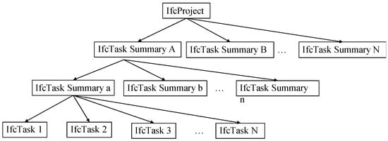
Figure 8.
Entities reference relationship in an IFC file.
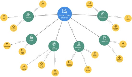
Figure 9.
Graph database.
Therefore, it is feasible and reasonable to adopt the graph database to store and twin the IFC-based information model. All the procedures are realized in Neo4j, which is a popular Java-based graph database [57]. There is a round-trip mechanism between the IFC files and the graph database.
Twinning the IFC files to the graph database. This paper will use Java to twin the IFC information model into the graph database. The process is divided into the following six steps.
Step1. Using IFC Java Toolbox to parse IFC files. The IFC Java Toolbox consists of three main parts: obtaining the Java class by parsing the IFC entity type, obtaining the Java type by parsing the IFC data content, and providing the object model IfcModel for IFC data to access.
Step 2. Based on IFC schema, constructing a dictionary of the IFC entities and its key-value is corresponding to IFC entities’ attributes;
Step 3. Specify the database path and create an EmbeddedGraphDatabse instance under the path;
Step 4. Generate the Node instance corresponding to the IFC entity through the designed createNode() method, and the information in the IFC entity is stored in the node’s properties through the key-value set by the dictionary;
Step 5. Create the relationship between nodes, which is the relationship between IFC entities, through the designed createRelationship() method.
Step 6. Accessing the graph database using Cypher command.
Therefore, an automatic algorithm to twin the IFC-based 4D construction information model to the Neo4j graph database is realized and the database can be used as a platform for participants to interoperate the construction information. Specifically, users can twin the IFC-based 4D construction information model to Neo4j, and the graph database-based information model can be uploaded to the cloud for all project participants to use. Project participants can fetch, modify, and update all the construction information they need through simple operation
Re-exporting the IFC files from the graph database. This part is used to re-export the IFC files from the graph database to complete the round-trip between the IFC files and the graph database. Although the construction information has good interoperability when it is twinned and stored in the Neo4j-based graph database, users sometimes need the IFC files with updated information to further utilize information in various BIM software. Therefore, an algorithm is developed in this paper, which can re-export the IFC information in the graph database into a complete IFC file. This algorithm’s core is to traverse the entire graph database’s information and output it into an IFC file. The output IFC files can be used in different BIM software which supports the IFC format.
6. Analyzing the Graph Database-Based and IFC-Based Construction Management Information Model
This section is the third part of the framework. In this section, graph database-based strategies to update data, automatically analyze construction schedules and visualize the 4D construction management information model are described.
6.1. Data Update
The ability to update the construction information in real-time is the most significant advantage of twinning the IFC information model into the graph database. The process of data updating is simple. Users can query the corresponding tasks in the graph database of the construction information they are interested in through a simple search. Benefitting from the graph database’s intuitive relationship, users can also get other information directly related to the construction information. For example, a user searches for a construction task and returns an IfcTask node, as well as the IfcResouce, IfcCostItem, and IfcProduct nodes that are directly associated with the IfcTask. After the user obtains the node, the node’s attributes can be updated according to the actual construction data to complete the update of the graph database-based and IFC-based information model.
6.2. Schedule Network Analysis
The schedule network of prefabricated buildings’ construction process can be automatically obtained after twinning the IFC-based 4D construction management model into the graph database without any manual work. Furthermore, this paper develops a graph-based algorithm to analyze the schedule network. The necessity to analyze the schedule network is reflected in two aspects. Firstly, the analysis of schedule networks can identify the tasks’ centrality in the schedule network, which can help managers adjust the resources’ allocation. Secondly, the parameters of schedule networks are significant in the Graph Neural Network (GNN), which will benefit further work in machine learning or deep learning [58]. The results of the schedule network analysis will be stored in the Pset_ScheduleNetworkAnalysis. The algorithm calculates three parameters in the schedule network.
Degree Centrality (DC): The DC is the total number of edges directed to a node and edges directed to others. The degree centrality of the node reflects the centrality of the construction task to other tasks. The greater degree centrality means that the delay of this node is more likely to cause the delay of other tasks in the construction network plan, which means the higher the risk caused by the delay of this task.
Closeness Centrality (CC): The CC of a node is the average length of the shortest path between the node and all other nodes in the graph, which quantifies how close the node is to others. Closeness centrality reflects the difficulty of intercommunication between nodes [59]. The larger the closeness centrality, the stronger the interaction between the construction tasks in the schedule network.
Betweenness Centrality (BC): BC is the number of shortest paths that pass through the node and quantifies the number of times the node acts as a bridge along the shortest path between two other nodes. Betweenness centrality reflects the pivotal role of nodes in the network [60]. The larger the betweenness centrality, the greater the construction task’s control effect on the schedule network’s other tasks.
The calculation methods of degree centrality , closeness centrality , and betweenness centrality are represented as follows:
where 𝑥, 𝑦, 𝑧 are different nodes, is the distance between nodes 𝑥 and 𝑦, is the total number of shortest paths from node y to node z, is the number of those paths that pass through node x, and N is the total number of nodes in this network.
DC(x) = [Count(Ek|StartNode(Ek) = x) + Count(Ek|EndNode(Ek) = x)]/(N − 1),
CC(x) = 1/∑y d(y,x),
BC(x) = ∑y≠x≠zd(y,x),
6.3. Delay Analysis
In addition to the automatic analysis of the schedule network, automatic delay analysis plays a critical role in the graph database-based information model. The analysis of delays includes two parts. The first part is to calculate the project schedule network’s critical path and store the critical path’s information in the extended IFC schema, which can be automatically complete by the graph-based algorithm. The graph-based algorithm proposed in this paper calculates the critical path by finding the path that has the longest duration. The IfcTask entity identified in the critical path will be associated with the extended property set Pset_CriticalPath to store the critical path’s information. Furthermore, project managers are interested in the following properties of each construction task: Earliest Finish Time (EF), Earliest Start Time (ES), Latest Start Time (LS), Latest Finish Time (LF), Slack Time. These insightful properties will also be easily calculated through the graph and then added to the graph, which is infinitely better than manually typing functions into several Excel cells.
The second part is to collect the construction information and analyze the delay. When the construction task is identified as its start time later than the last start time, its finish time later than the last finish time, or its delay time longer than the slack time, the IfcTask is associated with the extended property set Pset_DelayAnalysis. The result of the delay analysis is then be stored in the extended IFC schema, facilitating the managers to master the project progress. Furthermore, the programming developed by this paper will also analyze the impact on the overall construction duration due to the delayed task based on whether the delayed task occurs on the critical path or whether the duration of the delay exceeds the slack time of the task, thus assisting managers in their decision making.
6.4. 4D Visualization
The 4D visualization has two purposes. In the process of making a schedule, the visualization of the schedules allows the project team to check the schedule for completeness and ensure that sequencing and constructability requirements are satisfied [23]. During the actual construction, visualization of the construction process will present the delay tasks by extracting delay information and marking different colors, which will facilitate the project team’s control of the delay risks. In this section, Microsoft Project 2013 and Navisworks 2021 are used to visualize the information model with time information. Project and Navisworks are the most commonly used management software in construction management, but the IFC format is not well supported. Therefore, it makes the use of construction management information very inefficient and inconvenient. This framework proposes a method to display a process model extracting from the IFC-based information model in the 4D effect. The specific implementation process is as follows.
Initially, all the IfcTask entities in the created IFC information model are fetched automatically from the graph database’s retrieval algorithm. Next, the same method is used to extract the information of IfcCostItem entities, Pset_ScheduleNetworkAnalysis, Pset_Critical Path, and PSet_DelayAnalysis corresponding to each IfcTask entity. Afterward, all this retrieval information is written into Microsoft Project 2013. Finally, importing the Revit building model and Project files into Navisworks achieves the 4D display of construction information management.
7. Case Study
The IFC-based and graph database-based framework is validated through an engineering case of prefabricated buildings. In this case study, the comprehensive process of realizing, twinning, and analyzing the IFC-based 4D construction management information model of prefabricated buildings is executed. The result illustrates that this framework can enhance the managers’ control of processes by effective data interoperability and automatically analyzing construction schedules to prevent possible delays in advance.
7.1. Realizing the IFC-Based 4D Construction Management Information Model of Engineering Case’s Prefabricated Building
The engineering case selected is an academic building in Shanghai, China, with a total construction area of 135,858 square meters. The south tower of this building has 13 floors, and the north tower has 21 floors.
According to the framework proposed in this paper, an IFC-based 4D construction management information model of this case study’s prefabricated building is established.
The central part of this created IFC-based 4D construction management information model is shown in Table 7. A lot of components’ information is omitted from this listing, therefore, the span between the number of IFC file instances is large. In this IFC model, the project (#1) has a general construction task named TaskGroundLevel (#1036), which is composed of floors 1–13 construction tasks (#1039–#1063). Every floor’s construction task includes four summary tasks: fabrication summary task (#1065), transportation summary task (#1091), hoisting summary task (#1171), and installation summary task (#1143). Furthermore, taking fabrication summary task as an example, fabrication summary tasks nested by slab fabrication summary task (#1067), slab fabrication summary task (#1072), and roof fabrication summary task (#1085). The slab fabrication summary task is composed of tasks corresponding to specific components (#1067).
Table 7.
IFC file of IFC-based 4D construction management information model. (The single quotes in this table are necessary to observe the IFC standard’s regulation.).
Meanwhile, for each task of a specific component, the process information, resource information, and costs information related to the task are established in the information model. Taking the fabricate task of the 1st-floor slab as an example (#1067), the process information, labor resource information (#1247), material resource information (#1248), equipment resource information (#1249), cost information (#1253, #1254, #1255), schedule network analysis (#1257), and delay analysis (#1261, #1265) corresponding to the task are associated to it.
7.2. Twinning the IFC-Based 4D Construction Management Information Model of Engineering Case’s Prefabricated Building to Graph Database
Based on the algorithm proposed in Section 5, the IFC-based 4D construction management information model of the engineering case is twinned into the graph database to help the participants operate the IFC information model’s data. The interoperation platform based on the graph database is shown in Figure 10. Different colored nodes represent different entities in this figure, and the edge between two nodes represents the relationship between two entities. Further, the entities’ attributes are saved as the corresponding nodes’ properties. In this case, the twinned IFC-based information model is uploaded to the cloud. Therefore, the participants in different construction parts can access the database and interoperate the construction information. During the actual construction management, the modification of construction task information is often accompanied by the modification of related resources, cost, and other information, which is troublesome to operate. One of the enormous benefits of adopting the approach presented in this paper is that the participants can easily retrieve and operate the information they need, and all the related information associated with it via the graph’s edge. Another benefit to twin the IFC-based 4D construction management information model into a task-centered network is that the graph database-based algorithm can complete networks’ analysis that IFC files and Relational Database cannot complete. In conclusion, this step realizes the visualization and interoperation of the IFC information model which is difficult to understand and operate. This step lays a good foundation for the following analysis.
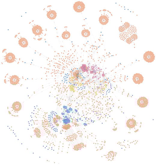
Figure 10.
Graph database-based information model.
7.3. Analyzing the Graph Database-Based and IFC-Based 4D Construction Management Information Model of Engineering Case’s Prefabricated Building
1. Data Update. The user’s operation of complex IFC files has been transformed into an easy-to-operate graph database. Since data update runs through the entire construction management and is described in detail in Section 6, it will not be repeated here.
2. Schedule Network Analysis. This paper analyzes the complex schedule network of this engineering case. The degree centrality, closeness centrality, and betweenness centrality of this schedule network are calculated by Formulas (1)–(3). The top 10 construction tasks in numerical value are shown in Table 8.
Table 8.
Top 10 tasks based on different centrality measures.
From the calculated results, we can see that Task 74 ranks first in all three parameters, indicating that it has a very important impact on the whole schedule construction network. In other words, if Task 74 is delayed, it will cause a large number of tasks in the schedule network to be delayed. It brings great risk for the whole construction schedule delay. With this information, managers should pay more attention to Task 74 and manage it better to avoid this task’s delay. This crucial information will be stored in the extended property set Pset_ScheduleNetworkAnalysis and associated with the corresponding IfcTask entities. The presentation of information from Task 74 and its associated datasets in the graph data is shown in Figure 11. The blue node representing Task 74 is associated with the pink node representing IfcPropertySet, including Pset_CriticalPath, Pset_ScheduelNetworkAnalysis, and Pset_DelayAnalysis.
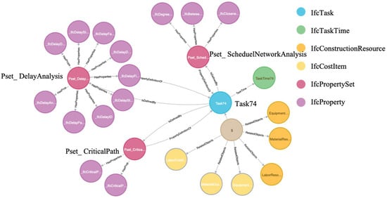
Figure 11.
Task74 with corresponding information.
3. Delay Analysis. According to the schedule information and schedule network automatically created in the graph database, this paper uses the graph’s algorithm to calculate the critical path. The critical path and its property are shown in Figure 12. In this figure, blue nodes represent IfcTask entities, green nodes represent IfcTaskTime, orange nodes represent IfcRelSequence, pink nodes represent IfcPropertySet named Pset_CriticalPath, and purple nodes represent IfcProperty. The IfcTask-IfcRelSequence-IfcTask line is the calculated critical path. Moreover, this paper also calculates every task’s significant properties by using the graph’s character and updating this information in the graph. These significant properties include Earliest Finish Time (EF), Earliest Start Time (ES), Latest Start Time (LS), Latest Finish Time (LF), and Slack Time. Once the tasks’ data collected in the actual construction illustrated delay is compared to the scheduled time, the program analyzes the delay. In this engineering case, Task 74 was completed three days later than it was expected to be completed. Based on the calculation of the graph, it will be immediately analyzed that the total construction period will be delayed by three days, thus facilitating the decision-maker’s control of the construction period. In addition, Task 74 will be associated with the extended property set Pset_DelayAnalysis, as shown in Figure 11.
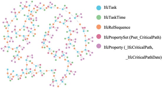
Figure 12.
The critical path identified from the graph database-based information model.
4. 4D visualization. Based on the above applications, the construction management information model with the time domain can finally be created. The graph database-based approach clarifies the association relationship between construction task entities and related information in the IFC information model. As mentioned before, the construction information is extracted from the graph database-based 4D construction management information model obtained in the previous steps to Microsoft Project. The construction information includes tasks’ time information and corresponding cost information, schedule network analysis information, critical path information, and delay information. Figure 13 demonstrates this step’s effect. In this Microsoft Project’s screenshot, the first column indicates the names of the IfcTask extracted from the graph database, and the subsequent columns indicate the process information, resource information, cost information, schedule network analysis information, delay analysis information, and critical path information corresponding to the IfcTask, respectively.
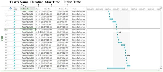
Figure 13.
Importing construction management information into project.
The next step is to import the Revit building model and MS Project file into Navisworks to create the dynamic presentation. The screenshot of the animation in Navisworks is illustrated in Figure 14. Through the construction simulation, the construction progress, cost, schedule network analysis information, delay analysis information, and critical path information can be known in real-time in the animation’s upper left corner. Additionally, the delay tasks also are identified with different colors. In this figure, the completed tasks are indicated by the color of the building facade, the unfinished tasks are indicated in green, and the red part indicates the delayed tasks.
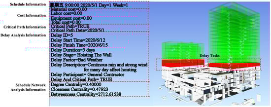
Figure 14.
Screenshot of animation in Navisworks.
Through this case study, the proposed framework is studied and verified step by step. Firstly, an IFC-based 4D construction management information model is created and expresses the extended construction management information. The graph database Neo4j can also be used to enable this IFC-based information model to be interoperated among different participants. In addition, it verified that the proposed framework could solve the problem that the IFC information model is hard to be modified and updated. Secondly, the graph database-based and IFC-based 4D construction information model is applied to update the data, analyze the schedule network, analyze delays, and dynamically present the 4D construction information model. The final results also prove that the graph database-based automated analysis approaches are practical, which is different from the traditional CPM. In short, the significance of this paper is to innovatively propose an IFC-based and graph data-based information model to solve the difficulties of ineffective data interoperation and unautomated schedule analysis in prefabricated buildings’ construction management.
8. Conclusions
In this research, a framework to realize, twin, and analyze the IFC-based 4D construction management information model of prefabricated buildings is proposed and validated with a construction project. The IFC-based framework is proposed to fill the gap that the IFC standard has difficulties in construction management information’s interoperability and automated analysis. This framework achieves four objectives: (1) A unified IFC-based construction management information model is established to integrate the construction management information needed in the construction process. It provides a feasible solution for managing the whole process of prefabricated building construction using a unified information model. (2) The algorithm to twinning the IFC-based 4D construction management information model into the graph database-based information model is designed. In this approach, IFC-based construction management information can be interoperated among different stakeholders, construction stages, and different BIM software. Furthermore, it lays the foundation of automated analysis of the graph-based information model. (3) The strategies to automatically analyze the schedule networks and analyze the delay are proposed. On the one hand, the analysis of the IFC-based and graph database-based construction management information model can identify the tasks’ centrality in the schedule network and then determine the tasks’ delay, which can help the managers control the construction process. On the other hand, the analysis of the construction schedule provides the necessary knowledge preparation for in-depth analysis and management of the construction process based on IFC and graphical databases. (4) The means to visualize the IFC-based 4D information model is given. Thus, the IFC-based information model can have a dynamic 4D presentation and visualize the results of construction schedules’ analysis.
In general, the contributions of this framework to the development of prefabricated buildings’ construction management are twofold. Firstly, this framework can promote the IFC-based construction management of prefabricated buildings by achieving the construction information’s interoperability, which is difficult to achieve in the current construction information management of prefabricated buildings. Secondly, this framework can enhance the managers’ control of processes by automatically analyzing construction schedules and visualizing the construction management information model based on graph database. This has greatly improved the efficiency of the CPM method, which used to have a time lag and be calculated manually.
Based on the results of this paper, related work can be further carried out. This research’s further works include: (1) Limited by BIM software functions, the resource information in the IFC-based 4D construction management information model cannot be well displayed. Further work can be the secondary development of relevant BIM software to realize the display of resource information. (2) In this extended information model, only prefabricated components are considered. More efforts are needed to include the cast-in-situ sections that have a more complicated construction process. (3) The graph and its parameters obtained based on the IFC twins can be further applied in the graph neural networks (GNN) to help the research on the efficiency improvement of the building construction process. (4) The framework developed in this paper can be extended to the scope of project life-cycle management and be the digital foundation of the energy consumption management during building operations and maintenance.
Author Contributions
Conceptualization, B.Y.; methodology, M.D., C.W. and B.L.; software, M.D.; writing—original draft preparation, M.D.; writing—review and editing, Z.W. and B.Z.; supervision, B.Y. All authors have read and agreed to the published version of the manuscript.
Funding
This study is supported by the National Key R&D Program of China (Grant No. 2018YFD1100900).
Conflicts of Interest
The authors declare no conflict of interest.
References
- Wang, H.; Zhang, Y.; Gao, W.; Kuroki, S. Life Cycle Environmental and Cost Performance of Prefabricated Buildings. Sustainability 2020, 12, 2609. [Google Scholar] [CrossRef]
- Wang, Q.; Guo, Z.; Mei, T.; Li, Q.; Li, P. Labor Crew Workspace Analysis for Prefabricated Assemblies’ Installation: A 4D-BIM-Based Approach. Eng. Constr. Archit. Manag. 2018, 25, 374–411. [Google Scholar] [CrossRef]
- Ji, Y.; Qi, K.; Qi, Y.; Li, Y.; Li, H.X.; Lei, Z.; Liu, Y. BIM-Based Life-Cycle Environmental Assessment of Prefabricated Buildings. Eng. Constr. Archit. Manag. 2020. [Google Scholar] [CrossRef]
- Xue, H.; Zhang, S.; Su, Y.; Wu, Z. Factors Affecting the Capital Cost of Prefabrication-A Case Study of China. Sustainability 2017, 9, 1512. [Google Scholar] [CrossRef]
- Baglivo, C.; Congedo, P.M. High Performance Precast External Walls for Cold Climate by a Multi-Criteria Methodology. Energy 2016, 115, 561–576. [Google Scholar] [CrossRef]
- Yu, S.; Liu, Y.; Wang, D.; Bahaj, A.S.; Wu, Y.; Liu, J. Review of Thermal and Environmental Performance of Prefabricated Buildings: Implications to Emission Reductions in China. Renew. Sustain. Energy Rev. 2021, 137, 110472. [Google Scholar] [CrossRef]
- Richard, R.B. Industrialised Building Systems: Reproduction before Automation and Robotics. Autom. Constr. 2005, 14, 442–451. [Google Scholar] [CrossRef]
- Eastman, C.M.; Eastman, C.; Teicholz, P.; Sacks, R.; Liston, K. BIM Handbook: A Guide to Building Information Modeling for Owners, Managers, Designers, Engineers and Contractors; John Wiley & Sons: Hoboken, NJ, USA, 2011; ISBN 978-0-470-54137-1. [Google Scholar]
- De Gaetani, C.I.; Mert, M.; Migliaccio, F. Interoperability Analyses of BIM Platforms for Construction Management. Appl. Sci. 2020, 10, 4437. [Google Scholar] [CrossRef]
- Chen, Q.; Hall, D.M.; Adey, B.T.; Haas, C.T. Identifying Enablers for Coordination across Construction Supply Chain Processes: A Systematic Literature Review. Eng. Constr. Archit. Manag. 2020, 28, 1083–1113. [Google Scholar] [CrossRef]
- Volk, R.; Stengel, J.; Schultmann, F. Building Information Modeling (BIM) for Existing Buildings—Literature Review and Future Needs. Autom. Constr. 2014, 38, 109–127. [Google Scholar] [CrossRef]
- buildingSmart ISO 16739-1:2018. Available online: https://www.iso.org/cms/render/live/en/sites/isoorg/contents/data/standard/07/03/70303.html (accessed on 15 March 2021).
- Xue, W.; Wang, Y.; Man, Q. Research on Information Models for the Construction Schedule Management Based on the IFC Standard. J. Ind. Eng. Manag. 2015, 8, 615–635. [Google Scholar] [CrossRef]
- Muller, M.F.; Garbers, A.; Esmanioto, F.; Huber, N.; Loures, E.R.; Canciglieri Junior, O. Data interoperability assessment though IFC for BIM in structural design—A five-year gap analysis. J. Civ. Eng. Manag. 2017, 23, 943–954. [Google Scholar] [CrossRef]
- Pan, Y.; Zhang, L. A BIM-Data Mining Integrated Digital Twin Framework for Advanced Project Management. Autom. Constr. 2021, 124, 103564. [Google Scholar] [CrossRef]
- Hamledari, H.; McCabe, B.; Davari, S.; Shahi, A. Automated Schedule and Progress Updating of IFC-Based 4D BIMs. J. Comput. Civ. Eng. 2017, 31, 04017012. [Google Scholar] [CrossRef]
- Mckinney, K.; Kim, J.; Fischer, M.; Howard, C. Interactive 4D-CAD. In Proceedings of the ASCE Third Congress on Computing in Civil Engineering, Anaheim, CA, USA, 17–19 June 1996; pp. 381–389. [Google Scholar]
- Wang, H.J.; Zhang, J.P.; Chau, K.W.; Anson, M. 4D Dynamic Management for Construction Planning and Resource Utilization. Autom. Constr. 2004, 13, 575–589. [Google Scholar] [CrossRef]
- Zhang, J.-P.; Anson, M.; Wang, Q. A New 4D Management Approach to Construction Planning and Site Space Utilization. In Proceedings of the Eighth International Conference on Computing in Civil and Building Engineering (ICCCBE-VIII), Moscow, Russia, 27–29 June 2012; pp. 15–22. [Google Scholar] [CrossRef]
- Chen, L.; Luo, H. A BIM-Based Construction Quality Management Model and Its Applications. Autom. Constr. 2014, 46, 64–73. [Google Scholar] [CrossRef]
- De Soto, B.G.; Rosarius, A.; Rieger, J.; Chen, Q.; Adey, B.T. Using a Tabu-search Algorithm and 4D Models to Improve Construction Project Schedules. In Creative Construction Conference 2017, Ccc 2017; Hajdu, M., Skibniewski, M.E., Eds.; Elsevier Science Bv: Amsterdam, The Netherlands, 2017; Volume 196, pp. 698–705. [Google Scholar]
- Li, C.Z.; Xue, F.; Li, X.; Hong, J.; Shen, G.Q. An Internet of Things-Enabled BIM Platform for on-Site Assembly Services in Prefabricated Construction. Autom. Constr. 2018, 89, 146–161. [Google Scholar] [CrossRef]
- Valluru, P.; Shetty, S. An Approach to Open-BIM Based Construction Project Management; Universitätsverlag der TU Berlin: Berlin, Germany, 2019; ISBN 978-3-7983-3104-4. [Google Scholar]
- Deng, Y.; Gan, V.J.L.; Das, M.; Cheng, J.C.P.; Anumba, C. Integrating 4D BIM and GIS for Construction Supply Chain Management. J. Constr. Eng. Manag. 2019, 145, 04019016. [Google Scholar] [CrossRef]
- Vieira, R.; Carreira, P.; Domingues, P.; Costa, A.A. Supporting Building Automation Systems in BIM/IFC: Reviewing the Existing Information Gap. Eng. Constr. Archit. Manag. 2020, 27, 1357–1375. [Google Scholar] [CrossRef]
- Ji, Y.; Qi, L.; Liu, Y.; Liu, X.; Li, H.X.; Li, Y. Assessing and Prioritising Delay Factors of Prefabricated Concrete Building Projects in China. Appl. Sci. 2018, 8, 2324. [Google Scholar] [CrossRef]
- Li, Z.; Shen, G.Q.; Xue, X. Critical Review of the Research on the Management of Prefabricated Construction. Habitat Int. 2014, 43, 240–249. [Google Scholar] [CrossRef]
- Bektas, S.; Talat Birgonul, M.; Dikmen, I. Integrated Probabilistic Delay Analysis Method to Estimate Expected Outcome of Construction Delay Disputes. J. Leg. Aff. Dispute Resolut. Eng. Constr. 2021, 13, 04520037. [Google Scholar] [CrossRef]
- Dallasega, P.; Marengo, E.; Revolti, A. Strengths and Shortcomings of Methodologies for Production Planning and Control of Construction Projects: A Systematic Literature Review and Future Perspectives. Prod. Plan. Control 2021, 32, 257–282. [Google Scholar] [CrossRef]
- Bokor, O.; Hajdu, M. Investigation of Critical Activities in a Network with Point-to-Point Relations. Procedia Eng. 2015, 123, 198–207. [Google Scholar] [CrossRef][Green Version]
- Lo, W.; Kuo, M.-E. Cost Impact of Float Loss on a Project with Adjustable Activity Durations. J. Oper. Res. Soc. 2013, 64, 1147–1156. [Google Scholar] [CrossRef]
- Seppänen, O.; Evinger, J.; Mouflard, C. Effects of the Location-Based Management System on Production Rates and Productivity. Constr. Manag. Econ. 2014, 32, 608–624. [Google Scholar] [CrossRef]
- Turkakin, O.H.; Manisali, E.; Arditi, D. Delay Analysis in Construction Projects with No Updated Work Schedules. Eng. Constr. Archit. Manag. 2020. [Google Scholar] [CrossRef]
- Yang, J.B.; Kao, C.K. Critical Path Effect Based Delay Analysis Method for Construction Projects. Int. J. Proj. Manag. 2012, 30, 385–397. [Google Scholar] [CrossRef]
- Menesi, W.; Hegazy, T. Why CPS Is Better than CPM? In Proceedings of the Annual Conference-Canadian Society for Civil Engineering, Ottawa, ON, Canada, 14–17 June 2011; Volume 3.
- Yu, K.; Froese, T.; Grobler, F. A Development Framework for Data Models for Computer-Integrated Facilities Management. Autom. Constr. 2000, 9, 145–167. [Google Scholar] [CrossRef]
- Lam, K.P.; Wong, N.H.; Shen, L.J.; Mahdavi, A.; Leong, E.; Solihin, W.; Au, K.S.; Kang, Z. Mapping of Industry Building Product Model for Detailed Thermal Simulation and Analysis. Adv. Eng. Softw. 2006, 37, 133–145. [Google Scholar] [CrossRef]
- Zhang, J.; Guo, J.; Wang, S.; Xu, Z. Intelligent Facilities Management System Based on IFC Standard and Building Equipment Integration. J. Tsinghua Univ. Sci. Technol. 2008, 48, 940–942, 946. [Google Scholar]
- Zhang, J.; Yu, F.; Li, D.; Hu, Z. Development and Implementation of an Industry Foundation Classes-Based Graphic Information Model for Virtual Construction. Comput. Aided Civ. Infrastruct. Eng. 2014, 29, 60–74. [Google Scholar] [CrossRef]
- Ma, Z.; Teng, M.; Ren, Y. Method of Extracting Static Data of Building Energy Consumption Monitoring from BIM Model. J. Harbin Inst. Technol. 2019, 51, 187–193. [Google Scholar]
- Xu, Z.; Wang, X.; Xiao, Y.; Yuan, J. Modeling and Performance Evaluation of PPP Projects Utilizing IFC Extension and Enhanced Matter-Element Method. Eng. Constr. Archit. Manag. 2020, 27, 1763–1794. [Google Scholar] [CrossRef]
- Akinci, B.; Boukamp, F. Representation and Integration of As-Built Information to IFC Based Product and Process Models for Automated Assessment of As-Built Conditions. ISARC Proc. 2002, 543–548. [Google Scholar]
- Seo, J.; Kim, I. Industry Foundation Classes-Based Approach for Managing and Using the Design Model and Planning Information in the Architectural Design. J. Asian Archit. Build. Eng. 2009, 8, 431–438. [Google Scholar] [CrossRef][Green Version]
- Park, J.; Cai, H.; Dunston, P.S.; Ghasemkhani, H. Database-Supported and Web-Based Visualization for Daily 4D BIM. J. Constr. Eng. Manag. 2017, 143, 04017078. [Google Scholar] [CrossRef]
- Gui, N.; Wang, C.; Qiu, Z.; Gui, W.; Deconinck, G. IFC-Based Partial Data Model Retrieval for Distributed Collaborative Design. J. Comput. Civ. Eng. 2019, 33, 04019016. [Google Scholar] [CrossRef]
- Weise, M.; Liebich, T.; Wix, J. Integrating Use Case Definitions for IFC Developments; Zarli, A., Scherer, R., Eds.; CRC Press-Taylor & Francis Group: Boca Raton, FL, USA, 2009; pp. 637–645. ISBN 978-0-415-48245-5. [Google Scholar]
- Lee, S.-H.; Kim, B.-G. IFC Extension for Road Structures and Digital Modeling. In Proceedings of the Twelfth East Asia-Pacific Conference on Structural Engineering and Construction (easec12); Fai, L.H., Ed.; Elsevier Science Bv: Amsterdam, The Netherlands, 2011; Volume 14, pp. 1037–1042. [Google Scholar]
- Chen, L.; Lai, H.; Deng, X.; Lv, Z. Research on Methods of Entity Extension in IFC Standard Domain Layer. J. Graph. 2015, 36, 282–288. [Google Scholar]
- xbim Ltd. Xbim Toolkit. Available online: https://docs.xbim.net/ (accessed on 15 December 2020).
- Solihin, W.; Eastman, C.; Lee, Y.-C. Multiple Representation Approach to Achieve High-Performance Spatial Queries of 3D BIM Data Using a Relational Database. Autom. Constr. 2017, 81, 369–388. [Google Scholar] [CrossRef]
- Marmo, R.; Polverino, F.; Nicolella, M.; Tibaut, A. Building Performance and Maintenance Information Model Based on IFC Schema. Autom. Constr. 2020, 118, 103275. [Google Scholar] [CrossRef]
- Beetz, J.; van Berlo, L.; de Laat, R. Bimserver.org—An open source IFC model server. In Proceedings of the CIP W78 Conference, Cairo, Egypt, 16–19 November 2010; p. 9. [Google Scholar]
- Lin, Y.-H.; Liu, Y.-S.; Gao, G.; Han, X.-G.; Lai, C.-Y.; Gu, M. The IFC-Based Path Planning for 3D Indoor Spaces. Adv. Eng. Inform. 2013, 27, 189–205. [Google Scholar] [CrossRef]
- Ma, L.; Sacks, R. A Cloud-Based BIM Platform for Information Collaboration.; IAARC (The International Association for Automation and Robotics in Construction): Auburn, AL, USA, 1 October 2016; Volume 33, pp. 581–589. [Google Scholar]
- Chen, Z.; Pu, Y.; Shelden, D.R. A Graph Database and Query Approach to IFC Data Management. Future Inf. Exch. Interoperability 2019, 28–36. [Google Scholar]
- Neo4j Inc. Graph Database Use Cases: Neo4j for Graph Data Science and AI. Available online: https://neo4j.com/use-cases/graph-data-science-artificial-intelligence/ (accessed on 15 December 2020).
- Huang, H.; Dong, Z. Research on Architecture and Query Performance Based on Distributed Graph Database Neo4j; IEEE: New York, NY, USA, 2013; pp. 533–536. ISBN 978-1-4799-2860-6. [Google Scholar]
- Avelar, P.; Lemos, H.; Prates, M.; Lamb, L. Multitask Learning on Graph Neural Networks: Learning Multiple Graph Centrality Measures with a Unified Network. In Artificial Neural Networks and Machine Learning—ICANN 2019: Workshop and Special Sessions; Tetko, I.V., Kůrková, V., Karpov, P., Theis, F., Eds.; Lecture Notes in Computer Science; Springer International Publishing: Cham, Switzerland, 2019; Volume 11731, pp. 701–715. ISBN 978-3-030-30492-8. [Google Scholar]
- Bavelas, A. Communication Patterns in Task-Oriented Groups. J. Acoust. Soc. Am. 1950, 22, 725–730. [Google Scholar] [CrossRef]
- Freeman, L.C. A Set of Measures of Centrality Based on Betweenness. Sociometry 1977, 40, 35. [Google Scholar] [CrossRef]


Publisher’s Note: MDPI stays neutral with regard to jurisdictional claims in published maps and institutional affiliations. |
© 2021 by the authors. Licensee MDPI, Basel, Switzerland. This article is an open access article distributed under the terms and conditions of the Creative Commons Attribution (CC BY) license (https://creativecommons.org/licenses/by/4.0/).