Featured Application
Injector nozzles are essential elements of internal piston combustion engines. Part of the energy during fuel injection is irretrievably lost due to friction. The process of manufacturing and controlling the main features is complicated. The main design features of the injector nozzles can be optimized in order to minimize frictional energy losses. The potential application of the results obtained is the process of designing and producing injector nozzles.
Abstract
The operation of injection apparatus in self-ignition engines results from the design, manufacturing technology and wear and tear during operation. The technical state of the injector apparatus significantly affects the engine performance, fuel consumption, toxicity and smoke opacity of outlet gases. The most unreliable element of the injection apparatus is the injector nozzle, the quality of which depends on the quality of construction and production, operating conditions and the of the fuels used, etc. One of the design parameters of the injector nozzles, determining the technical state is the geometry of the nozzle holes. An attempt was made to optimize the selection of the dimensions and surface condition of the spray holes to significantly affect the flow properties of the injector nozzles and, consequently, to decide on the size and form of fuel dosed streams to individual cylinders of a self-ignition engine and the quality of fuel atomization. In work, a simulation model was developed, and the pressure losses and the mass fluid of the injected fuel were minimized for selected significant geometric features, taking into account the influence of operating conditions. With the use of Mathematica software, simulation optimization methods and methods based on evolutionary algorithms were elaborated.
1. Introduction
The fuel injection process is the primary action influencing the reach of the desired parameters of the compression ignition engine cycle. The formation of the fuel stream and its disintegration during spraying, and then the formation of the fuel -air mixture depends on the physical properties of the fuel, the pumping pressure and the opening of the injector, air swirl, as well as the advanced design of the injector nozzle and the quality of workmanship [,,,].
Incorrect operation of injection equipment in compression-ignition engines, caused by imperfect workmanship and wear, significantly affects the engine performance, increased fuel consumption, toxic emission and smoke opacity of outlet gases. The research conducted so far has shown that the injector is the most unreliable element of the injection subsystem, and the nozzle in the injector []. Changes in its technical state significantly affect the engine operating parameters and the emission of harmful components of the outlet gases [,]. The injector nozzles work in very rugged conditions, with high pressures of the fuel and the working medium in the engine’s combustion chamber, and with the simultaneous interaction of the heat flux with flames and outlet gases [].
These are elements with a complex structure, high precision of workmanship and the required high durability. The introduced design changes and modernization of the engines produced require the improvement of the manufacturing technologies used. The purpose of these changes is to increase the maximum combustion pressure and mean effective pressure, reduce specific fuel consumption and increase durability and reliability.
The requirements for injector nozzles can be divided into design and technological. Design requirements are related to the functions, operation of the injector nozzle, durability and reliability, as well as interchangeability and standardization. Technological requirements, which determine the quality and cost of execution, include the possibility of obtaining high dimensional accuracy and surface smoothness as well as small errors in shape and position.
Studies have shown that many injectors are damaged in the initial period of operation [,]. The reason for such a situation may be the initial unfitness or low durability, which may result from the conditions of production, transport and storage [,]. The analysis of the quality control requirements of the manufactured injectors has shown that they are not very credible and not uniform. The modern state of the technology of producing nozzles does not ensure their hydrodynamic similarity because the dispersion of their geometrical dimensions is difficult to determine by means of industrial quality control methods [,].
One of the design dimensions of nozzles, determining their technical state, and at the same time subject to intensive wear, are the geometric features of the spray hole [,,,,,]. Changing the dimensions and condition of the spray hole surface significantly affects the flow properties of injector nozzles, and this, in turn, determines the size and form of fuel jets dosed to individual cylinders of a diesel engine and the quality of fuel atomization. Many investigations have shown that the nozzle hole geometry and its internal flow characteristics play an essential role in the spray formation [,,,] and combustion process [,,,].
This article intends to present a simulation model of the injector nozzle structure of a marine engine, which is part of the fuel injection subsystem. The main task is to develop a modern model, considering the latest theoretical and numerical achievements, of a marine engine injector nozzle. In the current article, it is expected that the method of optimizing the design of the injector nozzles will contribute to the reduction of fuel flow losses and the improvement of the efficiency of the piston internal combustion engines.
The injection subsystem tests can be carried out on a real object in operation [], on a real object in laboratory conditions [,] and with the use of computer simulation [,]. The essence of simulation studies of the fuel injection process is developing models that allow understanding the physical phenomena that determine the quality of injection.
2. Modeling and Experimental Studies of the Geometry of Injector Nozzles
2.1. Introduction
Modeling is the initial stage of the formal approach to the issues related to the analysis of the operation and the synthesis of technical objects. Modeling allows approximating the principles of organization, and principles of operation of the research object, enabling obtaining information about the modeled system. Modeling also allows reducing the cost and time of testing, especially for such complex and miniature elements as injector nozzles.
Models at the evaluation stage, design and production of objects are created for the needs of inference in simulation or experimental studies [,]. The model does not reflect a real object but is only a reflection of the knowledge currently possessed, cannot be treated as something permanent and is not subject to change.
An object model is a tool that allows describing an object and its behavior under various conditions through relations on a set of input and output quantities. The purpose of modeling is to obtain a reliable mathematical model that allows tracing the behavior of an object under various conditions. When building a model, the laws of physics are mainly used, which express the balance of forces, moments, flows, continuity equations and geometric relationships, as well as the results of experimental research [,,].
The structural model of the object shows the connections and the geometric location of the distinguished elements of the object. It is a graphical representation of elements for structural analysis. These models are usually descriptive and graphic []. A functional model of the device is a set of functional blocks denoted by, e.g., rectangles, blocks each containing several inputs and outputs, where the injection pump output may be the injection pipe input [,]. Appropriate selection of the design features of this subsystem, its control system and supervision of its operation is one of the fundamental problems faced by modern designers, producers and users of engines and injection apparatus.
2.2. Influence of Geometrical Features on the Functioning of the Injector
The nozzle-hole geometry is one of the important parameters considered in the engine to alter engine’s performance, combustion and emission courses. To improve the entire air-fuel mixture in self-ignition engines, swirl and turbulence characteristics need modification in the combustion chamber shape and injector nozzle geometry.
The flow characteristics at the orifice outlet for the four investigated nozzles were analyzed in terms of their stationary mass flow, effective outlet velocity and area coefficient []. The results showed that divergent nozzles exhibit high cavitation intensity. The geometry of injector nozzles significantly affected the characteristic spray behavior and emissions formation of diesel engines. In paper [], a nozzle concept consisting of orifices with convergent -divergent shapes was investigated. Three nozzles, characterized by different degrees of conicity, were compared to a nozzle with cylindrical orifices, which acts as a baseline.
In the article [], a method of calculation of the hydraulic working process of a diesel fuel feed system having an injector nozzle with different positions of its spray holes was tested. Research in self-ignition engine injector nozzle design for two groups of holes was carried out. Inlet edges of the first group of flow were in the sack volume and inlet edges of the second group were on the locking taper surface of the nozzle body. The coefficients of flow in both groups differ considerably and depend on the nozzle needle position. This makes it possible to distribute the injection quantity rationally by spray holes considering the operating conditions of the self-ignition engine and the combustion chamber zones.
Karra and Kong 2010 [] observed the 10-hole nozzle geometry hole nozzle had the best performance in the engine at full-load conditions. The number and cone of hole variations in the nozzle injector lead to better engine performance and reduced emissions in work by Lahane and Subramanian 2014 []. The combined effect of cylindrical shape with the 5-hole nozzle geometry reduced NOx emissions up to 45% and slightly reduced CO emissions of the engine as compared to that of a standard shape by Shivashimpi et al. 2018 [].
2.3. Hitherto Existing Methods of Optimizing the Geometry of Injector Nozzles
The static flow rate of high-pressure injector nozzles was characterized through measurements and computations as an optimization process of nozzle design []. Prototype injectors were fabricated by modifying multi-zone injection nozzles. Measurements of flow rate were compared with the computations with respect to the nozzle geometry and the needle lift. The initial cone angle was calculated and compared with measurements by the direct photographic imaging method. A parametric study was carried out to terms the flow rate and the initial cone angle for selected design parameters.
Experimental study and optimization were carried out in the layouts and the structure of the high-pressure common rail fuel injection system for a marine diesel engine []. A novel optimization solution to improve the steady-state performance of the common rail fuel injection system designed for a ship engine retrofitting was proposed. The tests concentrate on optimizing the hydraulic layouts and the structure parameters to manage and use the model. In tests, the modified multi-objective genetic algorithm was employed to the reduction of rail pressure fluctuation.
The nozzle needle design concept which was considered in the research project was focused on maximizing the contact area between the needle and its cartridge to reduce needle wear []. The injector feeding part was realized using two series of holes. The design was replenished by 3D numerical simulations which indicated the optimal feeding-hole number and geometry to obtain a maximum mass flow rate. The study’s results indicated that the hole number substantially influences the flow losses along the internal flow path and the global mass flow rate.
Cavitation inside the injector nozzle was observed as a critical phenomenon, which induces a decrease in the flow capacity of the nozzle, but also an increase in the spray outlet effective velocity. Some authors [] have also performed visualization tests on transparent nozzles, but most of these studies are performed in scaled-up or simplified injector nozzles due to difficulties in production and optical measurements in manufactured geometries.
An experimental research investigation was carried out to analyze the influence of conical and cylindrical orifice geometries on a common rail fuel injection subsystem []. This behavior of the injection rate in the different nozzles was characterized by using the non-dimensional parameters of cavitation number, discharge coefficient and Reynolds number. The results evidenced essential differences in the permeability of both nozzle geometries and resistance of the conical nozzle to cavitation.
In the paper, a nozzle flow model was used to design an injector nozzle and obtain initial spray conditions for the common rail injection system []. The injector for dimethyl ether needs nozzle holes with larger diameters and a higher sack volume for the same injection duration. Additionally, the needle lift and needle seat diameter should be increased to achieve a minimum flow area ratio.
In the conducted experimental investigation, an effort has been made to enhance the performance of a dual fuel combustion engine utilizing different nozzle orifices []. In work, the injector nozzle with 3, 4 and 5 holes, each having 0.2, 0.25 and 0.3 mm hole diameter, respectively, and injection pressure in the injector subsystem (varied from 210 to 240 bar in steps of 10 bar) were optimized. The configurations of re-entrant type combustion chamber and 230 bar pressure in injection subsystem, 4 hole and 0.25 mm nozzle have contributed to maximum performance.
Increasing the injection pressure course in injector space band downsizing the spray holes’ orifice diameter has been the principal measures for self-ignition engine to influenced fuel—ambient gas mixture formation and combustion processes []. Additionally, the combination significantly accelerates the mixing of fuel and ambient gas and greatly decrease the soot formation.
2.4. Numerical Simulations Description
In paper [], simulated performance at different load conditions for a constant speed self-ignition engine was determined using GT-Power software. The critical parameters were optimized for achieving the desired fuel nozzle hole diameter. A very close validation with less than 1% difference is achieved at full load. In comparison, a less than 10% difference is achieved at part loads. The simulation model predicts the power, torque, brake specific fuel consumption, in-cylinder pressure, outlet temperature and NOx with very good accuracy at different loads. The optimized spray hole diameter of the testing engine was validated with the experimental results and compared with the baseline model.
The work in [] studied a new sub model of simulation model that correlated the discharge coefficient of the injector nozzle with the design variables of the nozzle and injection conditions. This solution enables the prediction of the effect of microvariations in the nozzle hole geometry as well as the variations in the main design parameters on self-ignition evolution and combustion processes. The working cycle simulation model has predicted changes in engine performance and toxic emissions due to injector nozzle design changes.
The authors of the work in [] showed that separate measurement of these single jet flow injection quantities is necessary to evaluate the injection holes. A measuring adapter for the determination of the injection quantities for individual spray holes was elaborated here. The influence of variation in shape and geometry of the individual nozzle components on singlejet flow injection quantities can be measured and simulated with a measuring adapter. It was demonstrated that the smaller the spray hole diameter, the larger the mass flow difference between the individual nozzle holes due to the increase in variation in the manufacturing process. The macro- and micro-geometrical state of the nozzle hole surface and the transient areas of the nozzle interior into the spray hole have a strong influence on the flow conditions within the range in the space of the nozzle needle seat and within the spray holes and thus on flow stream values and flow symmetry. Design features such as the angle in which the inclination-angle of individual nozzle hole [], and manufacturing processdriven parameters, such as the shape of the grinding radius of spray hole inlet edge substantially, influence the quantity of fuel mass flux through the individual nozzle hole.
Fuel pressurization up to 300 MPa, as required by modern common rail self-ignition engines, resulted in significant variation of the physical fuel properties (density, viscosity, heat capacity and thermal conductivity) relative to those at atmospheric pressure and room temperature conditions [,]. The high acceleration of the fuel at velocities reaching 700 m/s as it is flowed through the nozzle hole orifices to induce cavitation was found. The simulations were assuming variable properties reveal two processes strongly affecting the fuel injection quantity and its temperature. The intense pressure and density gradients at the central part of the spray hole induce fuel temperatures even lower than that of the inlet fuel temperature. The local values can exceed the fuel boiling point and induce reverse heat transfer from the liquid to the nozzle’s metal nozzle body. Local values of the thermal conductivity and heat capacity affect the transfer of heat produced at the nozzle surface to the flowing fuel. That creates large temperature gradients within the flowing fuel, which must be considered for accurate simulations of the flow through injector nozzles.
Two different injector designs have been studied: one with sharp-inlet cylindrical holes and one with tapered holes with inlet rounding []. The findings indicated considerable changes in the flow development but also bulk flow values such as the volumetric efficiency of the injectors and the mean fuel injection temperature.
In this section, the main achievements of simulation modeling are described, together with a description of specific nozzle geometries studied, are presented. The analyzed state of knowledge shows that individual authors achieved partial results for various design solutions and under different conditions. The problems cannot be considered as solved but some steps have been achieved. Only a few authors have dealt with fuel flow losses resulting in pressure losses and temperature increases. The authors also took up this problem.
3. Research Results
3.1. Simulation of the Fuel Mass Stream through the Spray Holes
The fuel flow through the multi-hole injector nozzle can be compared to the flow rate when measured with a measuring orifice, e.g., a small orifice (Figure 1). The fuel mass flow qmi through the spraying hole, similarly to the measuring orifice or the nozzle, is determined by the relationship [,,]:
where Ar—spray hole cross-section, μr—flow number, Δp—pressure difference in the injector nozzle space (sack) pi and in the combustion chamber pc, ε—expansion number and ρ—density of the flowing fuel, determined for the conditions directly in front of the orifice.
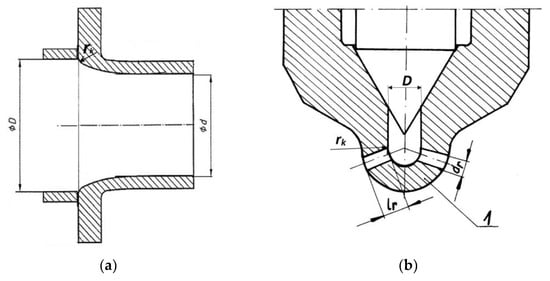
Figure 1.
Cross-section of a measuring nozzle compliant with ISO 5167-1:1991 (a) and a cross-section of an injector nozzle (b): d—diameter of the throat flow opening, D—diameter of the pipeline before the measuring nozzle, rk—radius of the nozzle edge rounding on the inlet side, dr—diameter of the nozzle hole, lr—nozzle hole length, 1—spherical surface of the injector nozzle.
The area of the spray hole can be calculated from the formula:
where drt—spray hole diameter at the temperature t.
Both cylindricity and circularity errors occur during production [] (Figure 2). In addition, there are material des decrements operation, as well as the deposit formation. Moreover, this diameter changes with temperature; therefore, the hole diameter drt at temperature t is:
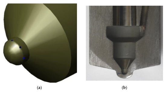
Figure 2.
The solid model of the injector nozzle (a) and image of cross-section of the nozzle hole with rounding (b).
The spray hole dimensions change during the measurement with the flow of the medium at a higher temperature. The thermal expansion of the hole considers the correction factor for thermal expansion kt:
where αt10| is the average coefficient of thermal expansion per 1 °C from the temperature of 20 °C to t1.
kt = 1 + 2αt(t1 − 20°)
There is also an increase in fuel temperature by 1 K at x for a pressure increase of 10 MPa [], whereby the formula can by:
where tpx—fuel temperature in place of x, td—fuel inlet temperature, ppx—fuel pressure at x and po—ambient pressure. In addition, the injector nozzle and the fuel heat up from the working medium in the combustion chamber by the Clapeyron equation [].
tpx = td + (ppx − po)/10
The flow number μr can be an experimentally determined coefficient for similar flows. In general, it is calculated from the formula []:
where: k1—correction factor of viscosity taking into account the influence of Reynolds number, k2—correction factor of roughness taking into account the influence of roughness of the internal surface of the pipeline in which the differential device is installed, k3—correction factor of the inlet edge bluntness, μo—the computational number of the flow corresponding to the actual value μ determined in the smooth bore for the highest Reynolds number (Remax).
μr = k1 k2 k3μo
The correction factor of viscosity k1 depends on the Reynolds number and the quotient of the flow diameter of the spray hole and the inflow channel Dt, which can be written as:
The correction factor for viscosity can be read from the diagram for the calculated Reynolds number and the quotient lrt/drt ([], p. 449) or a relationship can approximate it.
The correction factor k2 depends on the quotient of the flow diameter of the nozzle hole and the inlet channel, the quotient of the surface roughness ∆ and the channel diameter Dt, and the Reynolds number. Correction factor for nozzle holes k2 was calculated from the dependence []:
where lrt—nozzle hole length at temperature t and ∆—hole surface roughness.
The roughness of the surface of the injector nozzle sack was determined according to industry requirements and measurements using a roughness gauge for the sections of the spray channels.
The correction factor for the inlet edge defocus k3 depends on the quotient of the flow diameter of the nozzle hole and the inlet channel, the channel diameter in front of the hole Dt and the edge radius rk on the upstream inlet side of the spray hole. The correction multiplier k3 was determined based on the quotient of the edge rounding radius and the diameter of the spray hole rk/drt and the hole module m:
This relationship was approximated by a second-order polynomial in the form:
The design number of flow μo corresponds to the actual value determined in a smooth pipeline for the highest Reynolds number (Remax) and the quotient of the flow diameter of the spray hole and the inflow channel.
The Reynolds number can be calculated for the diameter ahead of the nozzle hole at temperature t or for the diameter drt (radius rrt):
where cg—average fuel flow velocity in the minimum cross-section, rht—hydraulic radius, vp,t—fuel kinematic viscosity for temperature t and pressure p and —absolute viscosity for temperature t and pressure p.
The kinematic viscosity can be calculated from the relationship:
The expansions number ε takes into account the change in the specific volume of the compressible fluid related to the pressure reduction as it flows through the spray hole. Fuel is a compressible liquid subordinated to Hooke’s law with the modulus of elasticity [].
The relationship between temperature and fuel density was also determined by the following relationship [,]:
where ∆ρ is the reduction of fuel density after heating by 1 °C, ∆ρ = 6.5 kg/m3.
ρp,t = ρ15 − ∆ρ(t − 15)
The viscosity of the fuel is important due to the use of different liquid fuels of different viscosities for the supply of reciprocating internal combustion engines.
The pressure losses on the way from the injection pump drive to the injector nozzle were calculated for two engine types in [,]. The absolute pressure loss ∆ω in the spray hole depends on the type of nozzle hole, its constriction, the flow rate and the differential pressure. For the shape compared to the orifice, it is calculated based on the formula []:
where β—spray hole narrowing is equal. The narrowing β of the spray opening is defined by:
Figure 3a shows the influence of surface roughness on pressure losses when flowing through the spray hole. This relationship has a minimum of 0.05 µm. Figure 3b shows the effect of the spray hole length on pressure losses. As the surface roughness increases and the spray hole length increases, the irreversible pressure loss increases non-linearly with related variables.
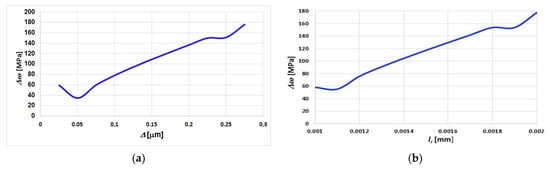
Figure 3.
An example of the influence of surface roughness (a) and the length of the spray hole (b) on pressure losses ∆ω.
Relative pressure losses were calculated from the relationship:
where ∆p = pi − pc—pressure difference in the nozzle sack and the combustion chamber.
The fuel mass flux qm, when flowing through the number of i spray holes can be determined by the following relationship []:
The value of these features is determined at the production stage. The final formula for the fuel mass flux was calculated by the following dependence:
Experimental measurements of the fuel mass flux and determination of flow characteristics for new and used injector nozzles were carried out on a flow test stand using calibration oil for many years [,]. These measurements made it possible to experimentally determine the flow coefficient μr and the spray holes’ average area. The pressure courses in the combustion chamber were calculated and measured using a resistance sensor with digital processing.
The mass of the injected fuel as a result of the pressure loss is lower:
Thus, the fuel mass flux, which should be maximized due to flow losses, depends on the following geometrical values and results from the type of fuel and the design of the internal combustion engine, resulting in the parameters of the working medium:
The latter relationship will be used to optimize for surface roughness losses ∆, the radius of the spray orifices on the inlet side rk, the influence of temperature t and pressure ∆p and pressure losses ∆ω. This means that when ∆ = 1, then there are no friction losses, and when ∆ = 0, there are such large friction losses that the mass flux of dosed fuel is equal to 0. In the simulation, the change in ∆ was assumed in the range from 0.3 to 1.0, in steps of 0.1. Various functions can approximate such a relationship.
From the point of view of friction losses, the value of pressure losses ∆ω is interesting, because the quantity is irretrievably lost, depending on the characteristics of the technical state determined at the production stage and changing during operation:
Therefore, there is a need to build a simulation model due to the optimization goal.
Based on the presented dependencies, the influence of selected design features on the pressure loss at the flow through the nozzle holes was presented. Figure 4a shows the effect of the number of flows through the nozzle holes on the pressure curve in the nozzle space. The diagram 4a shows that the influence of the spray hole flow coefficient μr on the pressure course in the nozzle space is significant. Therefore, there is a need to build a simulation model due to the optimization goal.
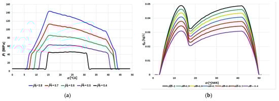
Figure 4.
Influence of the value of the flow coefficient μr on the pressure course in the injector nozzle space pi (a) and influence of the relative pressure losses
through the spray holes on the fuel mass flow qm (b).
On the other hand, Figure 4b shows the influence of the relative pressure drop on the mass fluid of the dosage fuel. The figure also shows a significant decrease in the mass fluid of the dosed fuel with an increase in the relative pressure loss caused by friction in the geometric profiles of the spray holes. Figure 4b shows the influence of relative pressure losses through the spray holes on the fuel mass fluid.
Experimental measurements were also made in the injection subsystem outside the engine and on actual selected internal combustion engines in the Marine Power Plants Laboratory of the Maritime University of Szczecin and on sea-going ships.
The total pressure in the injector space pi is the sum of the static pressure ps, which is the residual pressure pr, and the dynamic pressure pd depending on the speed of the pumped fuel:
where pr—residual pressure, εs—controlling indicator, taking the values 1 (when pi ≥ po) or 0 (when pi < po) and po—nozzle opening pressure. Each throttling in the injection subsystem is associated with a pressure drop, including, among others, the flow factor []. The results of the comparison of modeling and measurement on a real engine are shown in Figure 5. The measure of compliance of these two waveforms is the value of the correlation coefficient [], which was 0.847, which indicates a close relationship. This compatibility is satisfactory, but at the same time, encourages further improvement of the modeling and measurement method of the pressure course with the use of the Kistler sensor.
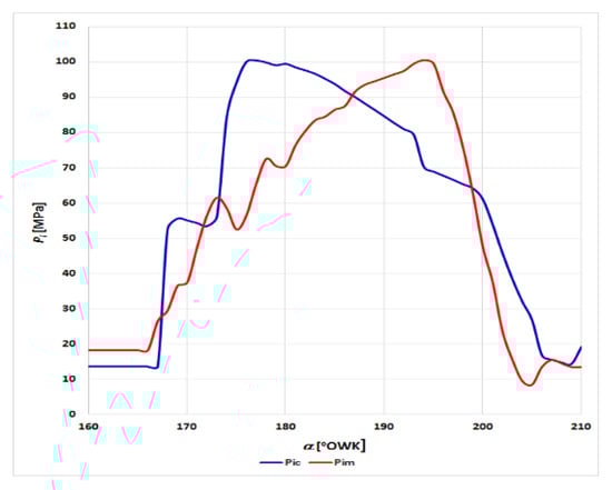
Figure 5.
Comparison of the pressure course of the calculated pic in the injector nozzle space and measured before the injector valve pim.
The course and these are consistent with those presented in the literature []. Relative pressure losses may exceed 50%, which leads to significant weight losses of the dosage fuel.
Additionally, carried out experimental measurements of the friction force between the body and the needle of the injectors of new and used injectors, which resulted in the patent award PL 234 940 B1. The friction forces varied, and in some cases very high, expressed in tons.
3.2. Optimization of the Selection of the Geometry of Injector Nozzles
In technical or economic sciences, optimization is one of the essential research tools. The use of more and more computing power of modern computers has allowed for the development of new optimization methods. Genetic algorithms, gradient methods, evolutionary algorithms, neural networks, finite element method are examples of optimization methods widely used in scientific research [,,]. In recent years, the application of mathematical optimization methods to practical solutions to material engineering problems [,,,] has been developed. The main task of optimization is the appropriate formulation of the analyzed problem, defining the set of searches and the optimization objective function. For this purpose, an area of permissible states Sp is introduced among the entire space of decision variables (state space Ss). If the objective function f: Ss → R and Sp ⊂ Ss, then the optimization task is to search for an element xopt ∈ Sp, that:
in the case of minimizing the objective function and
in the case of maximizing the objective function.
Gradient optimization methods use, in addition to the known values of the objective function, also its gradient values. They can be used only in those problems where the objective function has the form f: f: Rn → R and is differentiable in the Rn space.
The strategy of gradient methods comes down to two stages:
- (1)
- determining the direction of searching for the minimum using the gradient of the objective function or related quantities, and
- (2)
- selection of a step of appropriate length (constant or variable) following the found direction of the minimum search.
In the case of the conjugate gradient method used in this paper, the search direction is determined by designating conjugate directions. This method allows for the minimization of the objective function in n steps, where n is the number of variables present in the objective function [].
3.3. Optimization of the Parameters of Multi-Hole Nozzles
The research subject is multi-hole nozzles, both conventional and with electronically controlled injection, and the aim of the research is the impact of changes in the design of nozzles on fuel flow losses. The research object is a four-stroke medium-speed marine engine. The dependencies of the pressure course in the atomizer well and the fuel stream flowing out through the spraying hole for a given fuel setting can be approximated by various functions. Based on the formulas (8), (14) and (15), the pressure loss ∆ω can be represented as a function of six variables:
four of which relate to the geometric parameters of the atomizer: hole diameter drt, the diameter of the inflow channel to the hole Dt, surface roughness ∆ and channel length lrt. These four variables were analyzed in terms of minimizing pressure losses ∆ω. As the form of the function f is too complex, the analytical solution turned out to be impossible to implement. Therefore, in order to optimize the function f, the numerical conjugate gradient method was used. The following restrictions were imposed on the values of the variables:
- 0.00020 m < drt < 0.00032 m;
- 0.0004 m < Dt < 0.0010 m;
- 0.001 m < l < 0.002 m;
- 2.5 × 10⁻⁸ < ∆ < 2.8 × 10⁻⁷ m.
The pressure increase was assumed at the average level: ∆p = 2 × 10⁸ Pa.
For the assumed limits of variability, the function f reached the minimum for the extreme values of the variability ranges of the atomizer geometric parameters: ∆ωmin = 5.22858 × 10⁷ Pa for drt = 0.00032 m, Dt = 0.0004 m, lrt = 0.001 m and ∆ = 2.5 × 10⁻⁸ m.
The course of the function variability depends on the individual variables, with the values of the remaining variables fixed, witch makes it possible to determine the influence of these variables on the rate of changes in the value of the function ∆ω.
In the case of ∆, the change in the value of pressure loss ∆ω is the smallest and amounts to 1.03312 × 10⁶ Pa, which is about 2% of the minimum value of ∆ω (Figure 6).
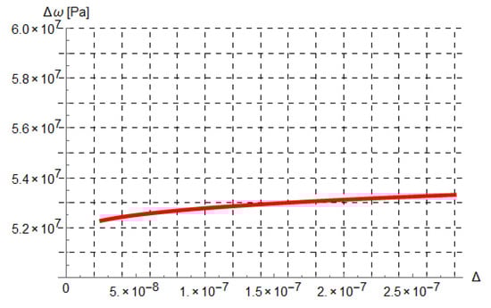
Figure 6.
The course of absolute pressure loss ∆ω, as a function of surface roughness ∆.
In the case of lrt, the change in the value of pressure loss ∆ω amounts to 1.55469 × 10⁶ Pa, which is about 3% of the minimum value of ∆ω (Figure 7).
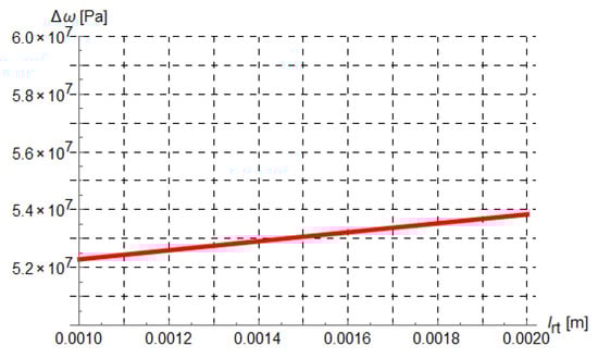
Figure 7.
The course of absolute pressure loss ∆ω, as a function of channel length lrt.
In the case of Dt, the change in the value of pressure loss ∆ω is the biggest and amounts to 1.48785 × 10⁸ Pa, which is about 285% of the minimum value of ∆ω (Figure 8).
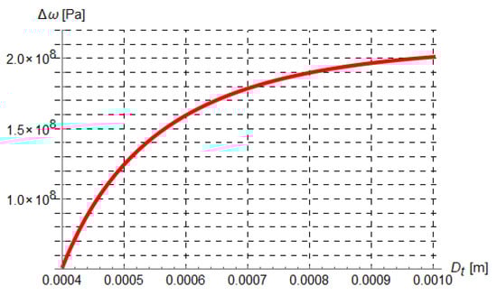
Figure 8.
The course of absolute pressure loss ∆ω, as a function of diameter of the inflow channel to the hole Dt.
In the case of drt, the change in the value of pressure loss ∆ω amounts to –1.17087 × 10⁸ Pa, which is about 240% of the minimum value of ∆ω (Figure 9).
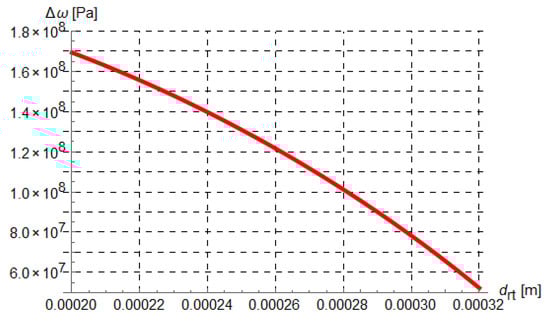
Figure 9.
The course of absolute pressure loss ∆ω, as a function of hole diameter drt.
In the case of the variables ∆ and lrt, Dt, as the variable grows, the values of ∆ω also increase. Only for hole diameter drt, the values of ∆ω decrease. The variables Dt and drt have the greatest influence on the change of the pressure loss value.
4. Conclusions
During the design and manufacture of injector nozzles, geometric features are formed that affect the performance. This is accompanied by irreversible pressure losses, which result in energy losses. For ecological and economic reasons, such losses should be minimized. Understanding the influence of geometric features allows to determine their significance and allows to determine their values to minimize pressure and energy losses. Such problems can be solved with the help of built structural and functional models and computer simulations. In addition to geometric features, pressure losses and fuel dosage are affected by the fuel quality and conditions of fuel injection. These studies focused on diesel fueling. Such problems can be solved using the constructed structural and functional models and computer simulation, and experimental tests of the internal combustion engine conditions and the injection subsystem outside the internal combustion engine. In terms of minimizing pressure losses, the optimal values of the injector nozzle geometrical features assume extreme values for the typical limitations of individual variables. In the case of the spray hole diameter (drt), hole surface roughness (∆) and spray hole length (lrt), the optimal values are the maximum permissible values of these variables. On the other hand, it is the lowest allowable value for the diameter of the inflow channel to the hole (Dt).
Based on the analysis of the variability of the pressure loss function depending on individual variables, it was found that both diameters have the most significant impact on the change ∆ω. On the other hand, roughness and the spray hole length on the pressure losses in the injector nozzles are negligible. Therefore, special attention should be paid to maintaining the appropriate dimensions of both diameters in terms of operation. Optimization of injector nozzle geometry of conventional and common rail systems could reduce manufacturing and operating costs and increase system performance significantly.
Further work may concern minimization of pressure losses in front of the injector nozzle, the influence of errors in the shape, friction losses between the needle and the injector body and position of the spray holes on pressure losses and the prediction of changes in the geometry of the nozzles during operation.
5. Patents
Monieta, J. The method and device for measuring the maximum friction force between the body and the needle of the injector in piston internal combustion engines Patent description PL 234940 B1, Patent Office of the Republic of Poland, Warsaw 2020, pp. 1–18. https://api-ewyszukiwarka.pue.uprp.gov.pl/api/collection/c2acbe35211e85ad27141555bd72d00d (accessed on 1 May 2020).
Author Contributions
Conceptualization, L.K. and J.M.; methodology, J.M.; software, L.K. and J.M.; validation, J.M.; formal analysis, L.K. and J.M.; investigation, J.M.; resources, J.M.; data curation, J.M.; writing—original draft preparation, L.K. and J.M.; writing—review and editing, L.K. and J.M.; visualization, L.K. and J.M.; supervision, J.M.; funding acquisition, L.K. and J.M. All authors have read and agreed to the published version of the manuscript.
Funding
This research outcome has been achieved under the research project “Ecological and economic aspects of the operation of selected elements of marine energy systems” No. 1/S/IESO/2014 and No. 1/S/IMFiCH/21 financed from a subsidy of the Ministry of Science and Higher Education for statutory activities.
Institutional Review Board Statement
Not applicable.
Informed Consent Statement
Not applicable.
Conflicts of Interest
The authors declare no conflict of interest. The funders had no role in the design of the study; in the collection, analyses or interpretation of data; in the writing of the manuscript, or in the decision to publish the results.
Nomenclature
| drt | nozzle hole diameter at temperature t |
| Dt | diameter of the incoming fuel stream determined for the conditions directly in front of the hole at the temperature t |
| k1 | correction factor of viscosity taking into account the influence of Reynolds number |
| k2 | correction factor of roughness taking into account the influence of roughness of the internal surface of the pipeline in which the differential device is installed |
| k3 | correction factor of the inlet edge bluntness for the inlet edge of the spray hole |
| kt | the correction factor for thermal expansion of the hole |
| lrt | spray hole length at temperature t, |
| m | spray hole module |
| qm | fuel mass flow as it flows through the number i of spray holes |
| qmi | fuel mass flow when flowing through the i-th nozzle hole |
| ppx | fuel pressure at x |
| Red | Reynolds number can be calculated for the diameter dr in front of the nozzle hole at temperature t and for the diameter |
| rk | radius of the nozzle edge rounding on the inlet side, |
| tpx | fuel temperature in place of x by 1 K at x for a pressure increase of 10 MPa |
| α | crankshaft rotation angle |
| β | spray hole narrowing |
| μo | the computational number of the flow corresponding to the actual value μr determined in smooth bore for the highest Reynolds number (Remax) |
| ∆ | hole surface roughness |
| ∆p | pressure difference in the injector nozzle space (sack) pi and in the combustion chamber pc |
| Ε | expansion number, |
| ηp,t | absolute viscosity of the fuel at atmospheric pressure p and temperature t |
| μr | fuel flow coefficient through the spray hole, depending on the geometrical dimensions |
| νp,t | fuel kinematic viscosity for temperature t and pressure p |
| ρp,t | fuel density at pressure p and temperature t |
| irreversible absolute pressure losses | |
| irreversible relative pressure losses |
References
- Benajes, J.; Pastor, J.V.; Payri, R.; Plazas, A.H. Analysis of the influence of diesel nozzle geometry in the injection rate characteristic. Trans. ASME J. Fluids Eng. 2004, 126, 63–71. [Google Scholar] [CrossRef]
- Idzior, M. A Study of Combustion Ignition Engine Injector Nozzle Parameters in the Aspect of Operating Properties. Ph.D. Thesis, Poznan University of Technology, Poznan, Poland, 2004. [Google Scholar]
- Piotrowski, I.; Witkowski, K. Marine Diesel Engines; Trademar: Gdynia, Poland, 2004; pp. 475–551. [Google Scholar]
- Yue, Z.Y.; Battistoni, M.; Som, S. Spray characterization for engine combustion network Spray G injector using high-fidelity simulation with detailed injector geometry. Int. J. Engine Res. 2020, 21, 226–238. [Google Scholar] [CrossRef]
- Monieta, J. Selection of diagnostic symptoms and injection subsystems of marine reciprocating internal combustion engines. Appl. Sci. 2019, 9, 1540. [Google Scholar] [CrossRef] [Green Version]
- Jung, D.-H.; Assanis, D.N. A reduced quasi-dimensional model to predict the effect of nozzle geometry on diesel engine performance and emissions. Proc. Inst. Mech. Eng. Part D-J. Automob. Eng. 2008, 222, 131–141. [Google Scholar] [CrossRef]
- Shivashimpi, M.M.; Alur, S.A.; Topannavar, S.N.; Dodamani, B.M. Combined effect of combustion chamber shapes and nozzle geometry on the performance and emission characteristics of C.I. engine operated on Pongamia. Energy 2018, 154, 17–26. [Google Scholar] [CrossRef]
- Som, S.; Ramirez, A.I.; Longman, D.E.; Aggarwal, S.K. Effect of nozzle orifice geometry on spray, combustion, and emission characteristics under diesel engine conditions. Fuel 2011, 90, 1267–1276. [Google Scholar] [CrossRef]
- Monieta, J.; Wasilewski, M. The utilize of mass flow for spraying holes evalution of marine diesel engines injection nozzles wear. Tribologia 2001, 5, 947–961. [Google Scholar]
- Monieta, J.; Łukomski, M. Methods and means of estimation of technical state features of the marine diesel engines injector nozzles type Sulzer 6AL20/24. Sci. J. Marit. Univ. Szczec. 2005, 5, 383–392. [Google Scholar]
- Karra, P.K.; Kong, S.C. Experimental Study on Effects of Nozzle Holes Geometry on Achieving Low Diesel Engine Emissions. J. Eng. Gas Turbines Power 2010, 132, 022802. [Google Scholar] [CrossRef]
- Lahane, S.; Subramanian, K.A. Impact of Nozzle Holes Configuration on Fuel Spray, Wall Impingement and NOx Emission of a Diesel Engine for Biodiesel–Diesel Blend (B20). Appl. Therm. Eng. 2014, 64, 307–314. [Google Scholar] [CrossRef]
- Shivashimpi, M.M.; Banapurmath, N.R.; Alur, S.A.; Dodamani, B.M. Optimization of nozzle geometry in the modified common rail direct injection biodiesel-fuelled diesel engine. Int. J. Ambient. Energy 2019, 1, 1–9. [Google Scholar] [CrossRef]
- Salvador, F.J.; De La Morena, J.; Carreres, M.; Jaramillo-Císcar, D. Numerical analysis of flow characteristics in diesel injectors nozzles with convergent-divergent orifices. Proc. Inst. Mech. Eng. Part D J. Automob. Eng. 2017, 231, 1935–1944. [Google Scholar] [CrossRef] [Green Version]
- Nerkar, A. Optimization and Validation for Injector Nozzle Hole Diameter of a Single Cylinder Diesel Engine using GT-Power Simulation Tool. SAE Int. J. Fuels Lubr. 2012, 5, 1372–1381. [Google Scholar] [CrossRef]
- Lopez, J.J.; Salvador, F.J.; De la Garza, O.A.; Arregle, J. Characterization of the pressure losses in a common rail diesel injector. Proc. Inst. Mech. Eng. 2012, 226, 1697–1706. [Google Scholar] [CrossRef] [Green Version]
- Kuenssberg Saree, C.; Kong, S.C.; Reitz, R.D. Modeling the effects of injector nozzle geometry on diesel sprays. SAE Pap. 1999, 108, 1375–1388. [Google Scholar]
- Borkowski, T. Marine diesel engine combustion influenced by injection nozzle and primary fuel atomization. J. KONES Powertrain Transp. 2007, 14, 45–54. [Google Scholar]
- Monieta, J. Functional model of injector of medium-speed marine diesel engine. J. KONES Powetrain Transp. 2007, 14, 423–428. [Google Scholar]
- Monieta, J. Modelling of the fuel injection of medium speed marine diesel engines. Combust. Engines 2017, 170, 139–146. [Google Scholar] [CrossRef]
- Zółtowski, B.; Cempel, C. Elements of the theory of technical diagnostics. In Engineering of Diagnostics Machines; Society of Technical Diagnostics: Bydgoszcz, Poland, 2004; pp. 86–105. [Google Scholar]
- Bogusławski, L. Laboratory Exercises in Fluid Mechanics; Poznan University of Technology: Poznan, Poland, 1999; pp. 73–81. [Google Scholar]
- Falkowski, H.; Hauser, G.; Janiszewski, T.; Jaskuła, A. Diesel Engine Injection Systems; Modeling; WKiŁ: Warsaw, Poland, 1989; Part 2. [Google Scholar]
- Shatrov, M.G.; Malchuk, V.I.; Skorodelov, S.D.; Dunin, A.Y.; Sinyavski, V.V.; Yakovenko, A.L. Simulation of fuel injection through a nozzle having different position of the spray hole ransient heating effects in high pressure Diesel injector nozzles. Period. Eng. Nat. Sci. 2019, 7, 458–464. [Google Scholar]
- Jang, C.; Bae, C.; Choi, S. Characterization of prototype high-pressure swirl injector nozzles, part II: CFD evaluation of internal flow. At. Sprays 2000, 10, 179–197. [Google Scholar] [CrossRef]
- Hu, Y.; Yang, J.G.; Hu, N. Experimental study and optimization in the layouts and the structure of the high-pressure common-rail fuel injection system for a marine diesel engine. Int. J. Engine Res. 2020, 4, 1850–1871. [Google Scholar] [CrossRef]
- Kolovos, K.; Koukouvinis, P.; Robert, M.; McDavid, R.M.; Gavaises, M. Transient cavitation and friction-induced heating effects of diesel fuel during the needle valve early opening stages for discharge pressures up to 450 MPa. Energies 2021, 14, 2923. [Google Scholar] [CrossRef]
- Han, S.W.; Shin, Y.S.; Kim, H.C.; Lee, G.S. Study on the Common Rail Type Injector Nozzle Design Based on the Nozzle Flow Model. Appl. Sci. 2020, 12, 549. [Google Scholar] [CrossRef] [Green Version]
- Yaliwal, V.S.; Banapurmath, N.R.; Gireesh, N.M.; Hosmath, R.S.; Donateo, T.; Tewari, P.G. Effect of Nozzle and Combustion Chamber Geometry on the Performance of a Diesel Engine Operated on Dual Fuel Mode Using Renewable Fuels. Renew. Energy 2016, 93, 483–501. [Google Scholar] [CrossRef]
- Nishida, K.; Zhu, J.Y.; Leng, X.Y.; He, Z.X. Effects of micro-hole nozzle and ultra-high injection pressure on air entrainment, liquid penetration, flame lift-off and soot formation of diesel spray flame. Int. J. Engine Res. 2017, 18, 51–65. [Google Scholar] [CrossRef]
- Kilic, A.; Lothar Schulze, L.; Tschöke, H. Influence of nozzle parameters on single jet flow quantities of multi-hole diesel injection nozzles. SAE Trans. J. Engines 2006, 115, 785–795. [Google Scholar]
- Anvari, S.; Taghavifar, H.; Khalilarya, S.; Jafarmadar, S.; Shervani-Tabar, M.T. Numerical simulation of diesel injector nozzle flow and in-cylinder spray evolution. Appl. Math. Model. 2016, 40, 8617–8629. [Google Scholar] [CrossRef]
- Theodorakakos, A.; Strotos, G.; Mitroglou, N.; Atkin, C.; Gavaises, M. Friction-induced heating in nozzle hole micro-channels under extreme fuel pressurisation. Fuel 2014, 123, 143–150. [Google Scholar] [CrossRef]
- Theodorakakos, A.; Mitroglou, N.; Gavaises, M. Simulation of heating effects caused by extreme fuel pressurisation in cavitating flows through diesel fuel injectors. In Proceedings of the 8th International Symposium on Cavitation CAV2012, Submission no. 216, Singapore, 13–16 August 2012; pp. 1–7. [Google Scholar] [CrossRef] [Green Version]
- Monieta, J. Reconstructing the complex geometry of the injection nozzle channels of marine diesel engines. Maint. Probl. 2016, 3, 65–76. [Google Scholar]
- Xu, L.L.; Bai, X.S.; Jia, M.; Qian, Y.; Lu, X.C. Experimental and modeling study of liquid fuel injection and combustion in diesel engines with a common rail injection system. Appl. Energy 2018, 230, 287–304. [Google Scholar] [CrossRef]
- Cichocki, A.; Unbehauen, R. Neural Networks for Optimization and Signal Processing; John Wiley & Sons: Toronto, ON, Canada, 1993. [Google Scholar]
- Kusiak, J.; Danielewska-Tułecka, A.; Oprocha, P. Optimization. Selected Methods with Examples of Applications; PWN: Warsaw, Poland, 2019. [Google Scholar]
- Tan, K.C.; Khor, E.F.; Lee, T.H. Multiobjective Evolutionary Algoritms and Applications; Springer: London, UK, 2005. [Google Scholar]
- Kusiak, J.; Danielewska-Tułecka, A.; Żmudzki, A. Optimization of metal forming processes using a new hybrid technique. Arch. Metall. 2005, 50, 609–620. [Google Scholar]
Publisher’s Note: MDPI stays neutral with regard to jurisdictional claims in published maps and institutional affiliations. |
© 2021 by the authors. Licensee MDPI, Basel, Switzerland. This article is an open access article distributed under the terms and conditions of the Creative Commons Attribution (CC BY) license (https://creativecommons.org/licenses/by/4.0/).