Article

Properties of Car-Embedded Vibrating Type Piezoelectric Harvesting System

Energy Conversion Research Center, Korea Electrotechnology Research Institute (KERI), Changwon 51543, Korea
*
Author to whom correspondence should be addressed.
Appl. Sci. 2021, 11(16), 7449; https://doi.org/10.3390/app11167449
Submission received: 30 June 2021 / Revised: 27 July 2021 / Accepted: 12 August 2021 / Published: 13 August 2021
(This article belongs to the Special Issue Automobile Energy Harvesting Technologies)

Abstract

:
We investigated the harvesting performance of a double piezoelectric generator, which was embedded into the engine block of a small passenger car. The resonance frequency is approximately between 37 and 52 Hz, where the cantilever showed maximum displacement. In reality, the cantilever has a vibrating characteristic, which dramatically reduces displacement, even when the operating frequency deviates slightly from the resonance frequency. To acquire a large mechanical energy-to-electrical energy conversion, a multiple-piezoelectric generator was employed to absorb the energy even when the vibration switched from a resonance to a non-resonance frequency. In this study, a variable mass box was designed and installed in the engine block of a car. The variable mass box consisted of the serial connection of two masses with different weights. The operating frequency deviated from a resonance to a non-resonance frequency within a few hertz (3~4 Hz); the reduction in vibration was lower, leading to a significant acquisition of the resulting power. This is due to the variable matching of the generator, realized by the action of dual mass. This type of generator was installed in the engine block and produced up to 0.038 and 0.357 mW when the engine was operating at 2200 and 3200 rpm, respectively.

1. Introduction

In recent years, automobiles have used multiple-sensor systems to monitor service conditions and optimize their operation [1,2]. The multiple-sensor systems require many batteries and more than 100 km of electrical cables to connect them to the main electrical board installed in front of the driver’s seat. The use of conventional batteries has environmental downsides, and electric cables produce a large amount of waste; therefore, there is a need to find self-powering methods for sensor systems. A self-powered system in vehicles and cars can be provided by energy harvesting, with consideration of the fact that vehicles generate large amounts of vibration and heat when in operation [3,4,5].
Piezoelectric energy harvesting is a typical method of converting external mechanical vibration into electrical energy. Several considerations have been proposed for piezoelectric generators [6,7,8] to enhance the mechanical-to-electric energy conversion. Most cases are classified into either the mechanical impedance matching of a piezoelectric device with an external vibration source, or the electrical impedance matching between a piezoelectric device and a rectifier-storage circuit. In the electrical impedance matching between the variable electrical signal coming from piezoelectric devices and the electrical circuit designed by rectifying storage, actively controlled switching converters have been used to improve the conversion efficiency. Resonant rectifiers consisting of switching resistor–inductor–capacitor (RLC) circuits have been used to effectively transfer power from a piezoelectric device to a diode rectifier [9,10,11]. Furthermore, a suitable DC–DC converter was employed to regulate the DC output voltage and to draw the maximum possible power from the piezoelectric device for a specific electrical load [12,13,14,15]. In mechanical impedance matching between an external mechanical vibration signal and the mechanical characteristics of a piezoelectric device, the usable approach is to match the resonant frequency of the piezoelectric generator with the ambient frequency of environmental vibration [16,17]. Mechanically matching the resonance frequency of a piezoelectric generator with that of an external vibration source is the most realistic scavenging system method based on piezoelectricity [18,19,20]. However, matching two frequencies is difficult because the ambient vibration in a vehicle is in a variable state [21,22,23]. To overcome this difficulty, piezoelectric system supplements can be considered. One method is the adoption of multiple piezoelectric generators whose resonant frequencies are somewhat different. Therefore, the resonance mode covers a frequency range that matches the variable vibration frequency source. Another method is to make sure that the frequency of the modulated generator is considered in response to the variations in the external vibration source. It is also important to find the places where large vibrations in the car can be observed: the car engine and nearby. Therefore, with these two considerations, in this study, two piezoelectric generators were connected to the engine block of a small passenger car, and their effectiveness and the factors needed to control the harvesting system were evaluated. Unlike a single piezoelectric generator, multiple piezoelectric generators may interfere with each other in terms of resonant mode and power amplitude. For an example of multiple piezoelectric generators, in this study two piezoelectric generators were employed and compared with a single piezoelectric generator in terms of resonant vibration frequency and power amplitude.
In this study, two cantilever-type piezoelectric generators were employed and encapsulated into a harvesting system box, which was installed in the engine of a small car. The performance of the piezo-generator was measured in the range of resonance frequency and evaluated at ambient vibrations.

2. Materials and Methods

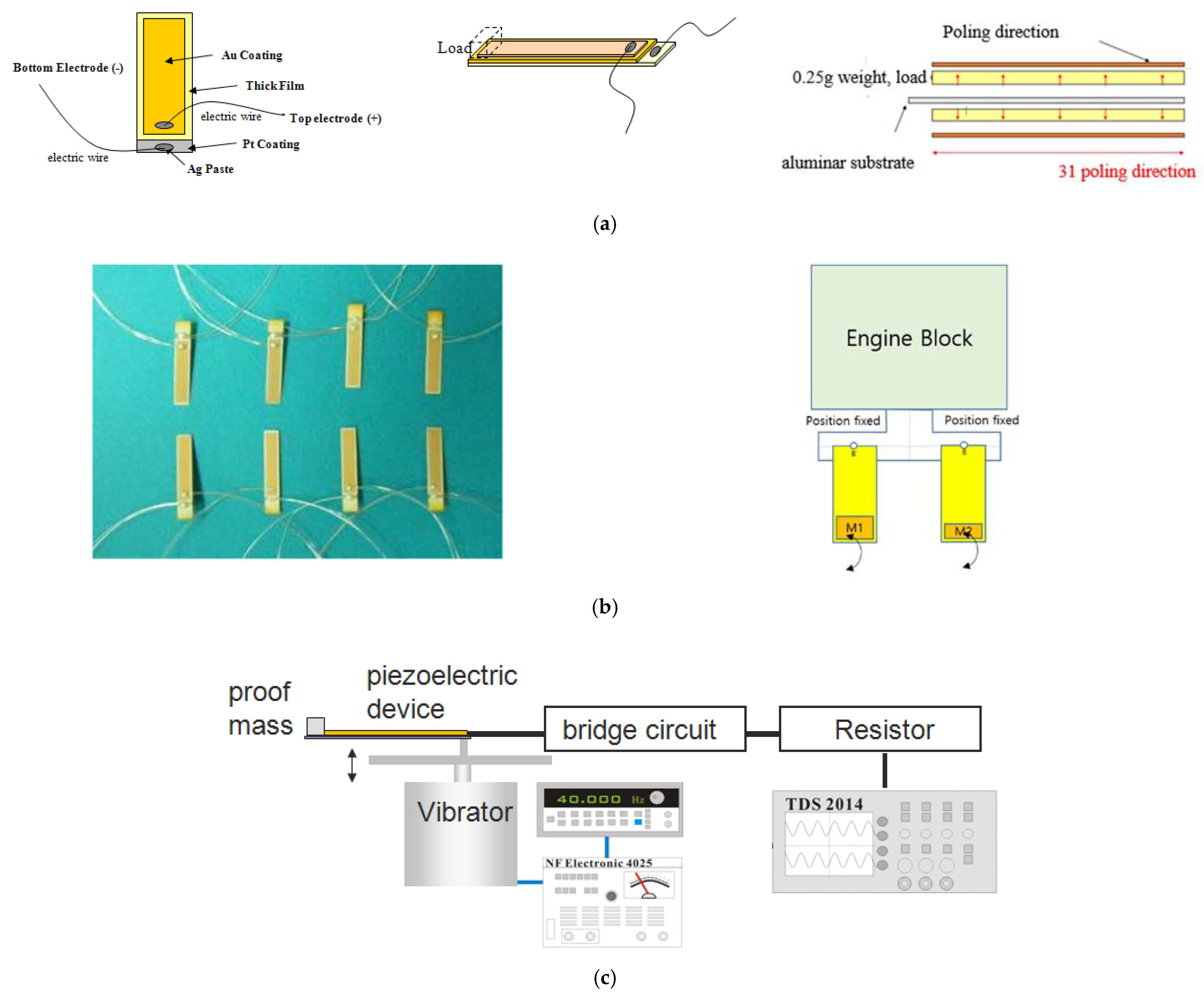
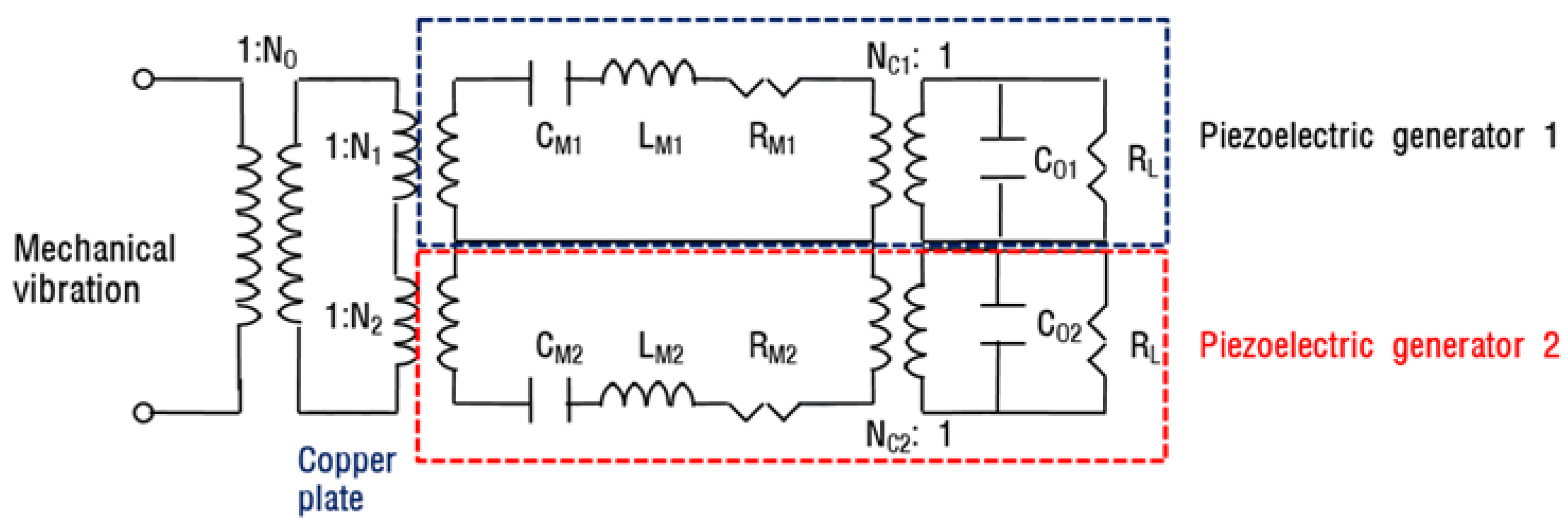
2.1. Design of the Generator

The structural geometry of the piezoelectric generator was designed with four piezoelectric layers. The characteristics of the cantilever type piezoelectric generator (PG) were examined with different payloads. A schematic diagram of the geometry is illustrated in Figure 1. The component, thickness, length, width, and height of the total PG layers are shown in Table 1.

2.2. Generator Fabrication

The piezoelectric ceramics used for this study were 0.2Pb(Mg1/3Nb2/3)O3–0.8Pb(Zr0.475Ti0.525)O3 (PMN-PZT) [11]. Figure 1 shows the geometry of the piezoelectric cantilever generator, which was made using the screen-printing method. A Pt electrode was coated by a sputtering process. Alumina (thickness = 0.1 mm) was used as a substrate. Then, a piezoelectric ceramic, PMN-PZT, was screen-printed on the Pt electrode. The printed substrate was kept at 50 °C for 10 min, followed by heating at 120 °C for 20 min. The sample was burned-out by remaining at 550 °C for 20 h, along with sintering at 1100 °C for 3 h. The Au was coated on the sintered body. The size of the piezoelectric cantilever is listed in Table 1. The resonance frequency was designed to be variable depending on the payload weight. The piezoelectric d31 coefficient and other physical properties of the ceramic materials were measured in a circular plate (diameter 18 mm, thickness 1 mm) using a resonance method, as listed in Table 2. The sample was poled with 3 kV/mm at 120 °C.

2.3. Measurement

The generator conversion performance was measured by a testing set-up (see Figure 1c). An electromagnetic shaker (B&K 4810) was used to supply reliable mechanical vibrations to the generator. The generator, consisting of a piezoelectric element and a copper sheet, was tightly fixed to an acrylic plate support, connected to the shaker by a screw pin. The shaker was controlled by a function waveform generator (Agilent 33220 A), incorporated with a power amplifier (NF 200 B). An accelerator was attached to the rod of the shaker. An oscilloscope (Tektronix TDS4014A) was used to monitor the voltage signal from the piezoelectric generator. The energy conversion test was performed by placing the piezoelectric power generator on the top part of the vibrating load of the electromagnetic shaker.
To determine their resonance frequencies, a 0.25~2 g payload was employed in the piezoelectric generators. Then, the vibration voltage from the generators was measured. To simulate the ambient vibration source, acceleration was set as 1.0 g (g = 9.8 m/s2). The rod of the shaker was vibrated in a sinusoidal form in a frequency range between 37 and 52 Hz. When the vibration was in action, the voltage was produced in the piezoelectric generator. Then, the voltage was rectified in a full-bridge circuit consisting of four germanium diodes. The power output acquired from the generator was determined by detecting the voltage drop obtained by the resistor connected to the generator and bridge circuit.
The power output was calculated as follows:
power = [Upeak-peak/2 √ 2] R2
where Upeak–peak is the load voltage of the rectified AC peak-to-peak and R is load resistance.
Then, the output voltage was regulated with an active voltage regulator. The output of each piezoelectric generator was rectified using full-wave bridge rectifiers. This unipolar output was then filtered and stored with 0.01 F storage capacitors.

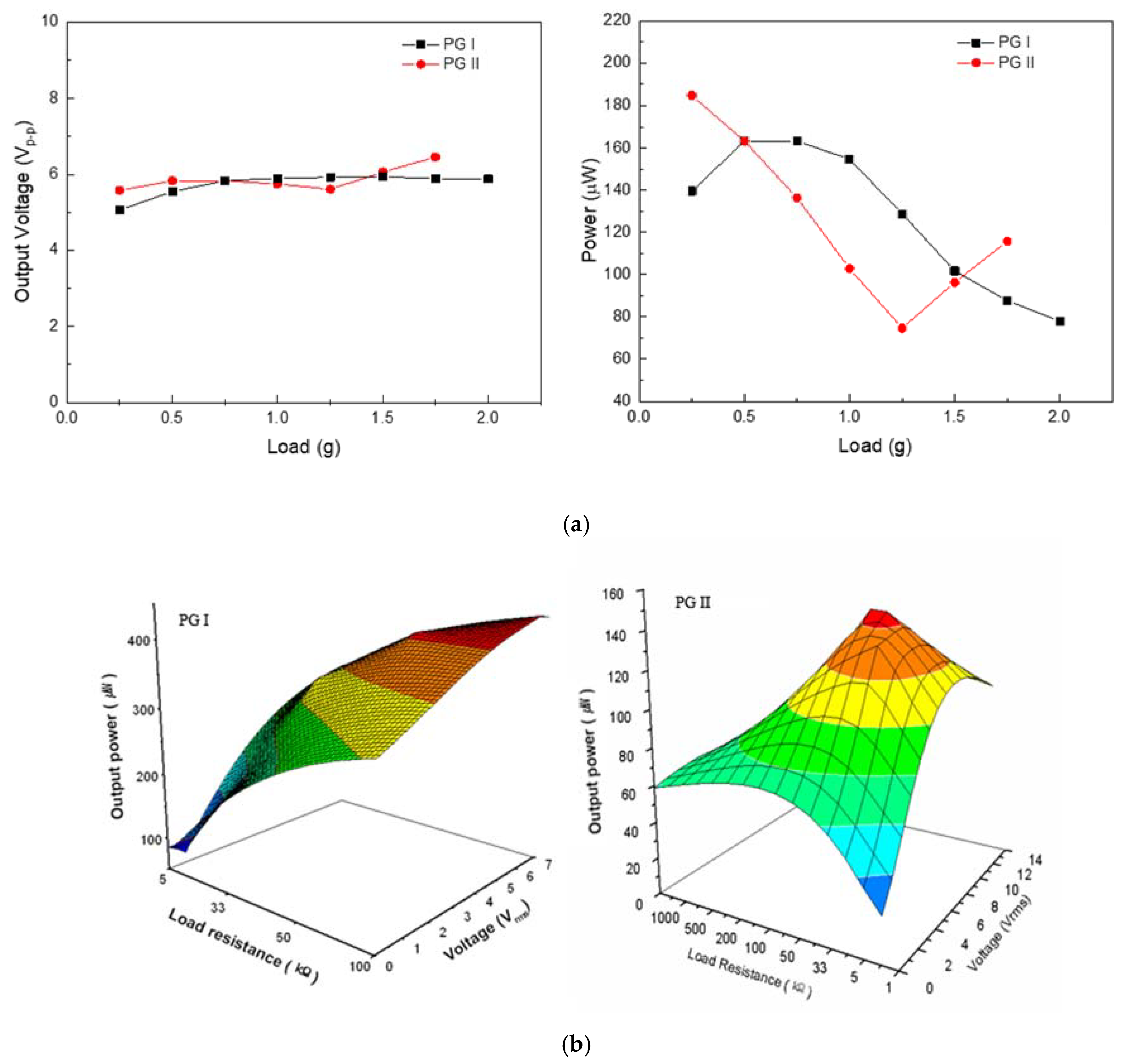
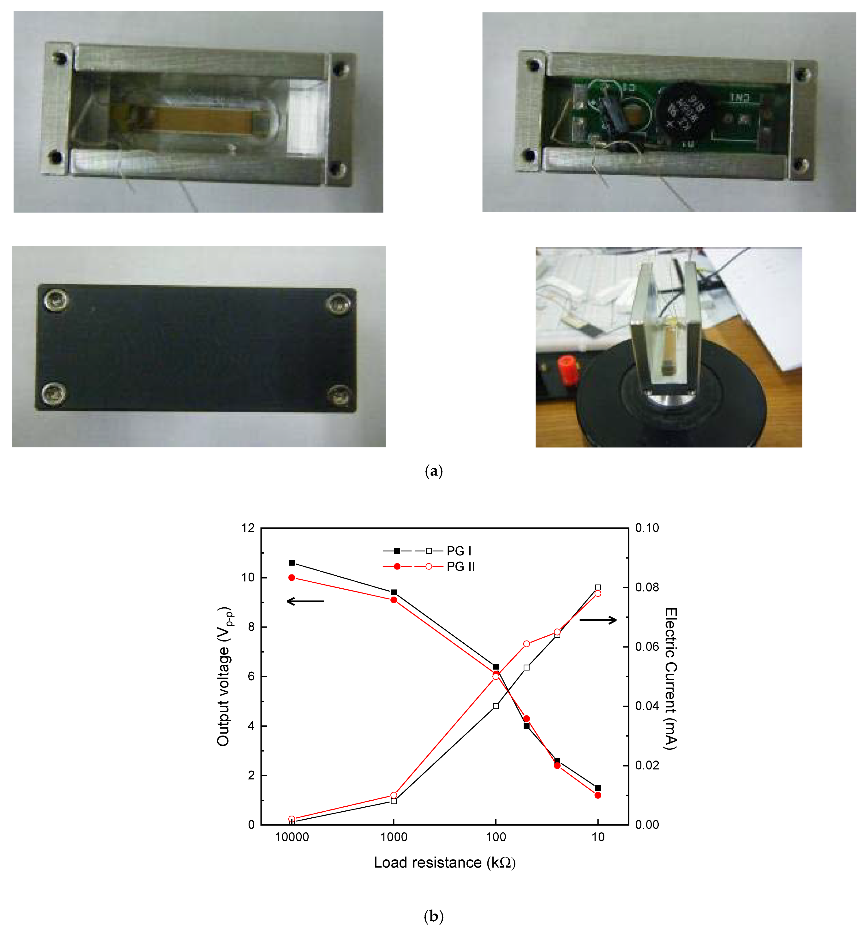
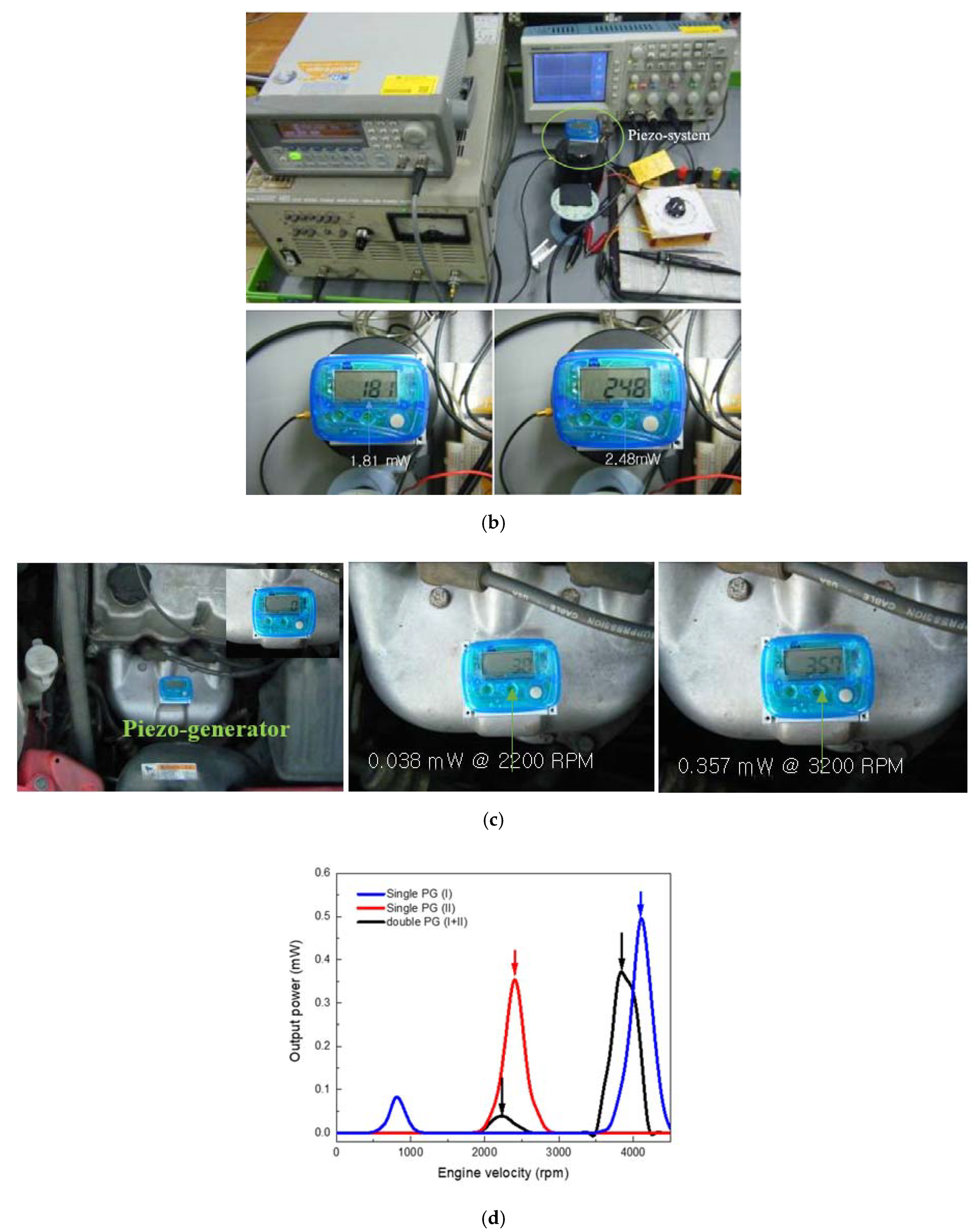
3. Results and Discussion

Figure 2 shows the general specifications of a piezoelectric generator, its employment on the engine block of a small passenger car, and the acceleration frequency of the engine block investigated in this study. A passenger car with 1000 cc capacity was chosen and the vibration of the engine block, with respect to frequency, was measured. The piezoelectric generators and their embedded energy harvesting system were designed according to the specifications of the car. Vibration amplitude versus frequency in the engine block was measured by an acceleration sensor (ReVibe Energy, Model D). The sensor was attached to the bottom of the car’s engine block. As shown in Figure 1b, the 37 to 52 Hz range was defined as the resonance frequency in the block. The acceleration peaks of 23~28, 34~40, and 48~54 Hz, observed in the figure, correspond with 1400~1800, 2000~2400, and 2900~3300 rpm (revolutions per minute) of the engine, respectively. To match the resonance piezoelectric harvesting frequency to that of the block, the two piezoelectric generators were used. According to the frequency–engine rpm relation and the acceleration–frequency relation, the largest vibration of >1 g (g = 9.8 m/s) was generated from the engine in the rpm range of 2000~2400 and 2900~3300. Therefore, the piezoelectric-type generator was designed to operate in resonance mode in 34~40 Hz (37 Hz in peak) and 48~54 Hz (52 Hz in peak), because cars have an engine operation with an rpm of 2000~4000 during normal performance.
The basic concept of energy harvesting, consisting of double piezoelectric generators with different payloads, is shown in Figure 3. The wide frequency range was selected as the resonance frequency range using a technique of serially connecting different masses. The masses were connected by a spring strip. Therefore, the resonance frequency characteristics of each mass could be observed, and a broad range of high vibration is presented. The position of the piezoelectric cantilever generator is the same, except for differences in mass. Figure 3 shows the output voltage and power versus payload in a piezoelectric generator operated at 37 and 52 Hz. At 37 and 52 Hz, the optimum piezoelectric generator was determined by a change in the payload of 0.25~2.0 g. In the case of 37 Hz, the piezoelectric generator with a payload of 1.0 g had maximums of 5.5 V and 0.152 mW. In the vibration at 52 Hz, a maximum voltage of 5 V and power of 0.190 mW were observed in the generator with a payload of 0.5 g. With a single piezoelectric device, a block consisting of a single piezoelectric generator and energy conversion circuit was designed, as shown in Figure 4. Each generator was separately connected to an electric storage circuit, due to the interference between generators. The circuit consists of a full diode bridge and charging capacitor. In addition, in the case of installation in the engine of a small car, the power was measured by connecting the LCD display with the power charging circuit. The LCD display shows the power (mW in unit) produced by the piezoelectric generators.
Figure 4 shows the system block, consisting of a single piezoelectric generator and charging circuit, and its measurement. Figure 4a contains photos showing the attachment of a piezoelectric generator onto the metal block, the positioning of an electric charging circuit inside the block, encapsulation of the block with an upper cover, and the measurement of a piezoelectric generator installed on the electromagnetic shaker. Figure 4b shows the output voltage and generated current of piezoelectric generator I (PG I) and piezoelectric generator II (PG II), operated at 37 and 52 Hz, respectively. Both generators have a maximum peak-to-peak voltage of 6 V under a resistive load of 100 kΩ at vibrations of 37 and 52 Hz, along with the creation of 0.04 mA current. From the voltage and current results, both generators could be calculated to have a maximum power of 0.12 mW. The optimum condition and performance of the PGI and PG II are listed in Table 3. Consequently, in order to acquire electric power in a relatively broad vibration condition ranging from 2000 to 4000 rpm, two generators were installed onto the metal block, along with an electric charging circuit and LCD display. The LCD display was attached for the direct observation of power generation without any additional connection.
Figure 5 shows each component, consisting of a piezoelectric generator, charging circuit, and display. The whole assembly process is shown in Figure 5a. Then, measurement of the assembled harvesting block was observed, as shown in Figure 5b. The power of 0.181 and 0.248 mW was observed in accordance with a vibration acceleration of 1 g (2200 rpm) and 1.2 g (3200 rpm), respectively. Figure 5c shows the installation of a piezoelectric harvesting system on the engine of a small car. Two images show the output power of 0.038 and 0.357 mW when the car runs with an engine velocity of 2200 and 4000 rpm, respectively. Figure 5d shows the relationship between the output power and engine velocity in the car. In a narrow range between 2200 and 3200 rpm, power generation was detected. However, no energy was stored in the harvesting block when the car ran in the other rpm condition. The generated power corresponds with 52% of that in the single piezoelectric generator operated in the car engine. When the system with a double piezoelectric generator was compared to the ones with a single piezoelectric generator, the rpm condition corresponding to the maximum output was somewhat different. The maximum rpm of a system with double piezoelectric generators was slightly shifted to the lower side. This may be the effective payload change in the harvesting system. The rpm or resonance frequency of PGs is affected by the effective stiffness and effective mass or payload.
Piezoelectric-type power generation devices are dependent upon the vibration amplitude and frequency. The cantilever-type piezoelectric device exhibited a significant power drop due to a small deviation in frequency. A method to store considerable power is to design a geometry structure to possess several resonant frequencies. As an example, we designed and fabricated the two cantilever generators, which have different masses, showing several resonant frequencies. The system investigated in this study can be considered with a simplified electrical circuit model, as presented in Figure 6 [24]. The interesting characteristics of the piezoelectric device are that the two piezoelectric generators are parallel-connected in the electrical equivalent model. The equivalent circuit model for the device can be thought of as two piezoelectric elements that are assembled back-to-back, similar to the multilayer piezoelectric transformer and other cases [24,25]. This model is only valid in a certain range of resonances. These devices are connected to each other by an ideal device representing the mechanical coupling between the two generators. To estimate the simplified resonant frequency, the equation of a single piezoelectric generator was used. The resonant frequency of the cantilever device was calculated by Equation (2) [26].
f n = v n 2 2 π 0.236 ω P E O ( l l m 2 ) 3 0.236 m ω P l 7 + Δ ml 3 ( l l m / 2 ) 3
with E O = 2 E P t P 3 3 + E P t c t P 2 + E P t c 2 t P 2 + t c 3 E sh 12 , m = 2 ρ P t P + ρ c t c , and Δ m = ρ m l m ω m h m , where l is the total length of the cantilever, lm is the length of the proof mass, m is the effective mass of the cantilever structure with the proof mass, and ωp is the width of the cantilever. ρp, ρc, tp, tc, Ep, and Ec are the densities, the thicknesses, and the Young’s modulus of the piezoelectric material and the base substrate (alumina in this study), respectively. Here, Δm is the combination of the effective mass of the piezoelectric generator in resonance mode and the effective mass of the piezoelectric generator in non-resonance mode. That is, in the double PG case, the effective mass Δm is larger than that of a single PG because of the interference between PG1 and PG2. Therefore, the resonant frequency shifted toward the lower side, and the total energy decreased slightly. The double PG shows large power generation in the two frequency ranges, near which a single PG has a resonant behavior, for example 2200 and 3200 rpm. However, the power of the double PG was not detected at the lower rpm. Meanwhile, the power of the single piezoelectric generator PG I was measured, which might be related to the damping of the total block. In addition, the frequency band width of the double PG widened compared to the single PGs, because the piezoelectric elements interfere with each other.
The conventional car has many sensor systems, including TMPS, pressure sensors, and chemical sensors, where the power ranges from 0.1 mW to several watts. The minimum power rate of the sensors used is approximately 0.5 mW for TPMS operation, which is comparable to the power acquired in this study.

4. Conclusions

An energy harvesting system consisting of a double piezoelectric generator was investigated and installed on the engine block of a small passenger car. In the harvesting system, the resonance frequency was approximately between 37 and 52 Hz, corresponding to 2200 and 3800 rpm of the engine. The energy harvesting system was installed in the engine block and produced up to 0.038 and 0.357 mW when the engine was operating at 2000~2500 and 2900~3300 rpm, respectively.

Author Contributions

S.-J.J. conceived the idea. S.-J.J. and D.-H.L. designed the experiments. D.-H.L. and D.-J.S. prepared the samples. D.-J.S. performed the measurements. B.-G.K. assisted in the discussion of the electric properties. D.-J.S. assisted in the discussion on the electrode in the device and made the final revisions. All authors contributed to the discussions. S.-J.J. and D.-J.S. wrote the manuscript with revisions from the other authors. All authors have read and agreed to the published version of the manuscript.

Funding

This research received no external funding.

Institutional Review Board Statement

Not applicable.

Informed Consent Statement

Not applicable.

Data Availability Statement

Not applicable.

Acknowledgments

This research was supported by the KERI Primary research program of MSIT/NST (No. 21A01026, 21A01007).

Conflicts of Interest

The authors declare no conflict of interest.

References

  1. Hamilton, M.C. Recent advances in energy harvesting technology and techniques. In Proceedings of the 38th Annual Conference on IEEE Industrial Electronics Society, Montreal, QC, Canada, 25–28 October 2012; pp. 6297–6304. [Google Scholar] [CrossRef]
  2. Basagni, S.; Naderi, M.Y.; Petrioli, C.; Spenza, D. Wireless sensor networks with energy harvesting. In Mobile Ad Hoc Networking: The Cutting Edge Directions, Basagni; Conti, M.S., Giordano, S., Stojmenovic, I., Eds.; John Wiley and Sons Inc.: Hoboken, NJ, USA, 2013; pp. 701–736. [Google Scholar] [CrossRef]
  3. Abdelkareema, M.A.A.; Xu, L.; Ali, M.K.A.; Elagouza, A.; Mi, J.; Guo, S.; Liu, Y.; Zuo, L. Vibration energy harvesting in automotive suspension system: A detailed review. Appl. Energy 2018, 229, 672–699. [Google Scholar] [CrossRef]
  4. Wang, H.; Jasim, A.; Chen, X. Energy harvesting technologies in roadway and bridge for different applications—A comprehensive review. Appl. Energy 2018, 212, 1083–1094. [Google Scholar] [CrossRef]
  5. Pancharoen, K.; Zhu, D.; Beeby, S.P. Temperature dependence of a magnetically levitated electromagnetic vibration energy harvester. Sens. Actuators A 2017, 256, 1–11. [Google Scholar] [CrossRef] [Green Version]
  6. Kim, H.W.; Batra, A.; Pruya, S.; Uchino, K.; Markley, D.; Newnham, R.E.; Hoffmann, H.F. Energy harvesting using a piezoelectric cymbal transducer in dynamic environment. Jpn. J. Appl. Phys. 2004, 43, 6178–6183. [Google Scholar] [CrossRef]
  7. Jeong, S.J.; Kim, M.S.; Song, J.S.; Lee, H.K. Two-layered piezoelectric cantilever generator for micro-power generator. Sens. Actuators A 2008, 148, 158–167. [Google Scholar] [CrossRef]
  8. Li, C.; Hong, D.; Kwon, K.H.; Jeong, J. A multimode relayed piezoelectric cantilever for effective vibration energy harvesting. Jpn. J. Appl. Phys. 2013, 52, 050202. [Google Scholar] [CrossRef]
  9. Guyomar, D.; Jayet, Y.; Petit, L.; Lefeuvre, E.; Monnier, T.; Richard, C.; Lallart, M. Synchronized switch harvesting applied to selfpowered smart systems: Piezoactive microgenerators for autonomous wireless transmitters. Sens. Actuators A Phys. 2007, 138, 151–160. [Google Scholar] [CrossRef]
  10. Mehraeen, S.; Jagannathan, S.; Corzine, K.A. Energy harvesting from vibration with alternate scavenging circuitry and tapered cantilever beam. IEEE Trans. Ind. Electron. 2009, 57, 820–830. [Google Scholar] [CrossRef]
  11. Liang, J.; Liao, W.-H. Improved design and analysis of self-powered synchronized switch interface circuit for piezoelectric energy harvesting systems. IEEE Trans. Ind. Electron. 2011, 59, 1950–1960. [Google Scholar] [CrossRef]
  12. Ottman, G.K.; Hofmann, H.F.; Lesieutre, G.A. Optimized piezoelectric energy harvesting circuit using step-down converter in discontinuous conduction mode. IEEE Trans. Power Electron. 2003, 18, 696–703. [Google Scholar] [CrossRef]
  13. Kong, N.; Ha, D.S. Low-power design of a self-powered piezoelectric energy harvesting system with maximum power point tracking. IEEE Trans. Power Electron. 2011, 27, 2298–2308. [Google Scholar] [CrossRef]
  14. Chen, N.; Jung, H.J.; Jabbar, H.; Sung, T.H.; Wei, T. A piezoelectric impact-induced vibration cantilever energy harvester from speed bump with a low-power power management circuit. Sens. Actuator A Phys. 2017, 254, 134–144. [Google Scholar] [CrossRef]
  15. Lefeuvre, E.; Audigier, D.; Richard, C.; Guyomar, D. Buck-Boost converter for sensorless power optimization of piezoelectric energy harvester. IEEE Trans. Power Electron. 2007, 22, 2018–2025. [Google Scholar] [CrossRef]
  16. Fang, H.B.; Liu, J.Q.; Xu, Z.Y.; Dong, L.; Wang, L.; Chen, D.; Cai, B.C.; Liu, Y. Fabrication and performance of MEMS-based piezoelectric power generator for vibration energy harvesting. Microelectron. J. 2006, 37, 1280–1284. [Google Scholar] [CrossRef]
  17. Roundy, S.; Leland, E.S.; Baker, J.; Carleton, E.; Reilly, E.; Lai, E.; Otis, B.; Rabaey, J.M.; Wright, P.K. Sundararajan, improving power output for vibration-based energy scavengers. IEEE Pervasive Comput. 2005, 4, 28–36. [Google Scholar] [CrossRef]
  18. Quattrocchi, A.; Montanini, R.; De Caro, S.; Panarello, S.; Scimone, T.; Foti, S.; Testa, A. A new approach for impedance tracking of piezoelectric vibration energy harvesters based on a zeta converter. Sensors 2020, 20, 5862. [Google Scholar] [CrossRef] [PubMed]
  19. Thainiramit, P.; Yingyong, P.; Isarakorn, D. Impact-driven energy harvesting: Piezoelectric versus triboelectric energy harvesters. Sensors 2020, 20, 5828. [Google Scholar] [CrossRef]
  20. Rubes, O.; Machu, Z.; Sevecek, O.; Hadas, Z. Crack protective layered architecture of lead-free piezoelectric energy harvester in bistable configuration. Sensors 2020, 20, 5808. [Google Scholar] [CrossRef]
  21. Challa, V.R.; Prasad, M.G.; Shi, Y.; Fisher, F.T. A vibration energy harvesting generator with bidirectional resonance frequency tenability. Smart Mater. Struct. 2008, 17, 015035. [Google Scholar] [CrossRef]
  22. Fakhzan, M.N.; Muthalif, A.G.A. Harvesting vibration energy using piezoelectric material: Modeling, simulation and experimental verifications. Mechatronics 2013, 23, 61–66. [Google Scholar] [CrossRef]
  23. Kong, N.; Ha, D.S.; Erturk, A.; Inman, D.J. Resistive impedance matching circuit for piezoelectric energy harvesting. J. Intell. Mater. Syst. Struct. 2010, 21, 1293–1302. [Google Scholar] [CrossRef]
  24. Platt, S.R.; Farritor, S.; Haider, H. On low-frequency electric power generation with PZT ceramics. IEEE/ASME Trans. Mechatron. 2005, 10, 240–252. [Google Scholar] [CrossRef]
  25. Fleming, A.J.; Moheimani, S.O.R. Adaptive piezoelectric shunt damping. Smart Mater. Struct. 2003, 12, 36–48. [Google Scholar] [CrossRef]
  26. Shen, D.; Ajisaria, J.; Choe, S.; Kim, D. The optimal design and analysis of piezoelectric cantilever beams for power generation devices. Mater. Res. Soc. Symp. Proc. 2005, 888, 271–276. [Google Scholar] [CrossRef]
Figure 1. Geometry of piezoelectric cantilever-type generator and its arrangement. (a) Geometry; (b) Piezoelectric generator; (c) Measurement of piezoelectric generator.
Applsci 11 07449 g001
Figure 2. Schematic illustrations of the piezoelectric generator, its employment in the engine block of a small passenger car, and acceleration–frequency relationship of the engine block. (a) Specifications of piezoelectric generator, energy harvesting system, and engine blocks of the passenger car investigated in this study; (b) Schematic illustration of the passenger car and acceleration–frequency relation of the engine block (23~28 Hz: 1400~1800 rpm, 34~40 Hz: 2000~2400 rpm, 48~54 Hz: 2900~3300 rpm).
Applsci 11 07449 g002
Figure 3. Output voltage and power of piezoelectric generator as a function of payload. (a) Output voltage and power versus load at 37 and 52 Hz; (b) Output power–voltage–load resistance of PG I at 37 Hz and PG II at 52 Hz.
Applsci 11 07449 g003
Figure 4. Fabrication and measurement of a single PG. (a) Piezo-generator, electric charging circuit, block capsulation, and measurement system; (b) Output voltage and power of a single PG (I and II) with payloads of 0.5 and 1.0 g.
Applsci 11 07449 g004
Figure 5. Fabrication and measurement of a harvesting system with double PGs (I + II). (a) Fabrication; (b) Measurement; (c) Installment in engine block; (d) Measurement of harvesting system with a single PG (I, II) and double PGs (I + II).
Applsci 11 07449 g005aApplsci 11 07449 g005b
Figure 6. Simplified equivalent circuit model representing a double piezoelectric cantilever generator.
Applsci 11 07449 g006
Table 1. Geometry of piezoelectric generator fabricated in the present study.
Piezoelectric LayerAlumina Layer
Width
(Wp, mm)
Length
(lp, mm)
Thickness (mm)Layer No.Width
(Wp, mm)
Length
(lp, mm)
Thickness (mm)
5100.0548430.1
Table 2. Property of piezoelectric ceramic.
CompositionDielectric Constant (εr)Electromechanical Coupling CoefficientPiezoelectric
d31 Coefficient (pC/N)
Piezoelectric g31 Coefficient (10−3 Vm/N)Quality Factor, Qm
0.2Pb(Mg1/3Nb2/3)O3–0.8Pb(Zr0.475Ti0.525)O318710.692101180
Table 3. Optimum conditions and performance of two piezoelectric cantilever generators.
SamplePiezoelectric
Generator I
Piezoelectric
Generator II
Resonance Frequency (Hz)3752
Payload (g)10.5
Load Resistance (kΩ)100100
Voltage (Vrms)5.55
Power (mW)0.1520.19
Publisher’s Note: MDPI stays neutral with regard to jurisdictional claims in published maps and institutional affiliations.

