Abstract
We consider the development of ligand-assisted growth processes for generating shape-anisotropic nanomaterials. Using statistical mechanics, we analyze the conditions under which ligand-assisted growth of shape-anisotropic crystalline nanomaterials from solution can take place. Depending on ligand-facet interaction energy and crystal facet area, molecular ligands can form compact layers on some facets leaving other facets free. The growth process is then restricted to free facets and may result in significant anisotropy in crystal shape. Our study uncovers the conditions for ligand-assisted growth of nanoplatelets and nanowires from isotropic or anisotropic seed nanocrystals of cuboid shape. We show that in contrast to nanoplatelets, ligand-assisted growth of nanowires requires certain anisotropy in the ligand-facet interaction energy.
1. Introduction
Semiconducting nanoparticles, nanoplatelets and nanowires (nanofibers) are at the heart of modern optoelectronics and photovoltaics [1,2,3,4,5,6,7,8,9,10,11,12,13]. Therefore, the fabrication of such structures with controllable sizes and size distributions is amongst the highest priorities to improving the functional properties of multiple nanodevices. Fabrication methodology of semiconducting nanoparticles (quantum dots) [2,9,14,15,16,17,18] as well as that of anisotropic objects like nanoplatelets [3,5,6,10,19,20,21,22,23] and nanowires [7,8,11,13,24,25] are in continuous development. A very promising bottom-up fabrication approach is based on molecular ligand-assisted growth (LAG) from the appropriate solutions [12,18,23,26,27]. Interaction of various molecular ligands with nanomaterial surfaces are reviewed in [28], and their role in the synthesis of nanoparticles is described in [29]. The LAG process allows for greater control of particle shape [17,27] and size distribution [18,30] and also for obtaining highly shape-anisotropic nanocrystals out of isotropic materials.
Shape-anisotropic crystal growth can take place in solutions containing molecular ligands binding crystal surfaces. Recently, it has been shown [20,22,23,27] that molecular ligands can form compact layers on wide enough crystal facets inhibiting any further growth on these facets. At the same time, the narrower facets remain intact and support crystal growth. For cuboid crystals with rectangle facets, this phenomenon results in the predominant formation of nanoplatelets. The shapes of cuboid crystals at the onset of a ligand-layer formation may be different, showing different aspect ratios of rectangular facets. However, it remains unclear how these shapes may affect the ligand-assisted formation of nanoplatelets. In this letter, we show that crystal shape plays a very important role in LAG and may result in the formation of both nanoplatelets (NPLs) and nanowires (NWs).
2. Model and Methods
We start with a cuboid seed at the onset of the LAG regime, and we are interested in understanding the role of this cuboid’s aspect ratios (the relative edge sizes) in the final shape of the crystals. The choice of cuboid seeds is convenient for quantitative characterization of the growing crystal shape and does not mean that the described approach is not applicable to other seed shapes (see the last paragraph in Results and Discussion for details). According to a recent study [23], the LAG regime takes place when the formation of a compact ligand layer on a wide enough crystal facet is much quicker than the crystal growth itself on this facet. It is convenient to quantify this process in terms of the ligand-layer formation probability depending on the crystal facet width. The characteristic parameter selecting appropriate facets is the size of the ligands’ critical nucleus. The ligand-layer formation probability can be represented (e.g., Equation (2) in Ref. [23]) as
where is the nucleation probability, and represents the probability for the layer to decay after its formation. It is clear that can be taken as constant as soon as the width of the crystal facet is equal to or exceeds the size of ligands’ critical nucleus (LCN). In contrast, the decay probability expressed in terms of excess free energy for decay is
which apparently depends on both the facet width X and its length Y. Here is the free energy of the ligands’ critical nucleus, and is that of ligands’ compact layer on the facet. Assuming for simplicity that the ligands in the compact layer are arranged in a square lattice and expressing the crystal facet sizes in the lattice units, the total number of ligands in the layer is while the number of ligands on the layer borders is . In such arrangement, each ligand binds four of its nearest neighbours with the bond energy equal to ( and, like all interaction energies in this paper, is measured in units, with temperature T assumed constant). With these simplifications, the Helmholtz free energy for the ligand layer deposited onto crystal facet from solution is given by
where () is the ligand-facet interaction energy for the xy facet, is the number concentration of ligands in the surrounding solution. Here we take into account that the ligand layer surface energy is equal and that the entropic contributions to free energy associated with the change in rotational degrees of freedom of ligand molecules upon their binding to crystal surface are effectively taken into account by a suitably adjusted value of .
The expression for the free energy (3) also applies to the LCN with size . It is convenient to express all spatial parameters in units, obtained by minimising Equation (3).
The lengths and are obtained in the same way. Using Equation (4), we rewrite Equation (3) in the form.
Note that for the LCN with , Equation (5) reduces to . Substituting this and Equation (5) into Equation (2), we obtain a decay probability for the layer:
where . Choosing the threshold to be so that for values of W equal or below 0.2, the compact layer of ligands is stable, we obtain the condition for y as a function of x.
3. Results and Discussion
Equation (7) represents the condition for the existence of a stable, compact layer of ligands on the two xy facets of a 3D cuboid crystal. This means that the third dimension, z, of the crystal is fixed, i.e., the crystal is not growing in the z-direction. In contrast, the reverse condition means that the xy facet does not support a ligand layer, and the crystal grows in the z-direction. Using these inequalities, we can analyze the conditions that lead to growing nanoplatelets and nanowires. The growth of nanoplatelets requires continuous growth in the x- and y-directions, which implies the following conditions
Without loss of generality, we have chosen a xy facet with . It is useful to rewrite the inequalities in Equation (8) in the form
where the boundary functions
define the boundary lines between the two states of the corresponding facet: (i) a facet covered with the compact layer of ligands and (ii) a free facet without any ligand layer. As can be seen from the second and third relations in Equation (10), the asymptotic values , , and reflect the anisotropy in LCN sizes.
3.1. Ligand-Assisted Growth of Nanoplatelets
Taking as an example the parameter values , we analyse the shape of growing crystals by plotting the corresponding boundary functions in Figure 1. We assume that the compact layer of ligands is first formed on the xy facet at the point indicated on the boundary function (red curve in Figure 1a).
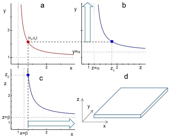
Figure 1.
Illustration of ligand-assisted growth of a nanoplatelet from an ideal cuboid crystal and anisotropy of the LCN sizes and . The curves represent the boundary functions given by Equation (10): (a) , (b) , and (c) with parameters . The points , and on the corresponding curves indicate the formation of compact layers of ligands on the xy, zy and xz facets, respectively. The compact layer of ligands is supposed to be formed first at the point . Therefore, the z-edge of the crystal at this point has to be significantly lower than . (b) The vertical arrow indicates the growth of the crystal’s y-edge for . (c) The horizontal arrow indicates the growth of the crystal’s x-edge for . (d) Nanoplatelet-like shape of the crystal growing with after its xy-facet is covered with a compact layer of ligands.
For this to happen, the initial z-edge value of the crystal has to be below —see Figure 1b,c. Then, for , the edges y and x are free to grow indefinitely, as indicated by large blue arrows on panels b and c, without intercepting the boundary lines , respectively. This growth of y- and x-edges results in a platelet-like shape, as illustrated in panel d. For , the growing y- and x-edges will eventually intercept the corresponding border lines (blue) and stop growing, thus forming a finite-sized cuboid or platelet. Note that the chosen anisotropy in LCN sizes , which is due to the anisotropy in the ligand-facet energy , makes the z-range for the nanoplatelet formation a bit broader, i.e., compared to in the isotropic case . Thus, Figure 1 shows that in this parameter regime, only platelets and cuboids can be formed.
3.2. Ligand-Assisted Growth of Nanowires
The picture is completely changed if we choose slightly different anisotropy in LCN sizes with, for example, . Then, looking at the conditions
one can also expect the formation of nanowires. The corresponding construction is illustrated in Figure 2. Panel (a) in this figure is identical to that in Figure 1a. Figure 2b illustrates the range of z-edge values, for which either a nanoplatelet (blue arrow in the range ) or a nanowire (red arrow in the range ) can grow. The reason why nanowires require the condition becomes clear in Figure 2c, which shows that for these z-edge values, the growing x-edge will ultimately cross the red boundary curve. Crossing this curve means that the xz-facet becomes covered with a compact layer of ligands, thus fixing the length of the crystal’s y-edge. The x-edge would still grow and lead to the formation of a nanowire-like crystal shape. It is worth noting that this kind of shape can be produced only if the anisotropy in LCN sizes is such that only one of the crystal facets, e.g., yz-facet, has a larger LCN size than the other two (xy- and xz-facets).
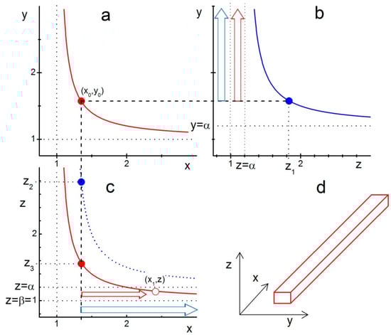
Figure 2.
Illustration of ligand-assisted growth of a nanowire from model cuboid crystal with the anisotropy of LCN sizes and . The curves represent the boundary functions given by Equation (10): (a) , (b) , and (c) with the parameter values . The points , and on the corresponding curves indicate the formation of a compact layer of ligands on the xy, zy and xz facets, respectively. The compact layer of ligands is supposed to be formed first at point ; therefore, the z-edge of the crystal at this point has to be significantly lower than . Blue arrows in (b,c) indicate the growth of nanoplatelets with similar to those in Figure 1. Red arrows in (b,c) indicate the growth of nanowires with , as in this z-range, the x-edge of the crystal grows until it reaches the red line at the point , indicating that the crystal’s xz-facet gets covered with a compact layer of ligands thus fixing the y-edge length. (d) A nanowire-like shape of the crystal growing with after its xy- and xz-facets are covered with a compact layer of ligands. For , the growing x- and y-edges would intercept the corresponding border lines (blue in (b) and red in (c)) and form a finite-sized cuboid.
These two simple cases of LCN sizes anisotropy when two of the crystal facets have the same size can be easily generalized. As can be seen in Figure 2c, the nanowire-like crystals are formed in the range (the coordinate system is chosen such that ), which means that for efficient fabrication of nanowires using the LAG method, one has to find a way of achieving a large enough difference between and for the seed crystals.
It is worth pointing out that the cuboid morphology characterized by three different ligand-facet interaction energies is quite generic. If all the energies are different, it describes the crystals with orthorhombic symmetry. In the case of equal ligand-facet interaction energies, we have the case of cubic crystal symmetry; using the LAG regime, it is possible to generate a platelet if the seed shape is a platelet of appropriate thickness (see discussion of Figure 1). If only two ligand-facet interaction energies are equal, then we reproduce tetragonal crystal symmetry. The approach can easily be extended onto hexagonal crystal symmetry and even the cylindrical shape of the seed crystals. To qualitatively illustrate this, recall that the key parameters in our approach are the ligand-facet and ligand-ligand interaction energies, which along with the ligand concentration in the solution, determine the ligand critical nucleus size. The latter is specific for each crystal facet. In the case of uniaxial seed shape (tetragonal, hexagonal, cylindrical), the growth of nanowires along the z-axis proceeds when the side crystal facets are covered with the compact layer of ligands. This happens when the ligand critical nucleus size is small enough compared to the shortest edge of the side facet. At the same time, the ligand critical nucleus size for the facet perpendicular to the z-axis has to be large enough to prevent the formation of the compact ligand layer. In most cases, these two conditions are fulfilled when the ligand-facet interaction energies for the side facets (or side surface of a cylinder) are significantly higher than that for the facet (surface) perpendicular to the z-axis (see discussion of Figure 2).
4. Conclusions
We have analyzed the possibility of ligand-assisted growth from solution for seed cuboid crystals in the form of nanoplatelets and nanowires. The main result of our analysis is intuitively clear: a stable growth of nanoplatelets requires either a suitably shaped (plate-like) isotropic seed crystal or a crystal with the following property: a single facet has much higher interaction energy with the molecular ligands than the other two. In contrast, successful growth of nanowires is possible only for anisotropic materials, in particular for those in which seed crystals have one crystal facet with much lower interaction energy with molecular ligands than the other two. We have demonstrated that the shape-anisotropic ligand-assisted growth also depends on the shape of cuboid seed crystals, which means that fine control of the process requires a preselection of an ensemble of seed cuboid crystals with the right anisotropy. This study provides a qualitative guide for the future developments of the bottom-up fabrication methods based on ligand-assisted growth from solution.
Author Contributions
Conceptualization, V.M.B. and A.G.; methodology, V.M.B.; formal analysis, V.M.B.; writing—original draft preparation, V.M.B.; writing—review and editing, A.G. All authors have read and agreed to the published version of the manuscript.
Funding
This work was supported by the Engineering and Physical Sciences Research Council grant EP/R020205/1 to AG.
Institutional Review Board Statement
Not applicable.
Informed Consent Statement
Not applicable.
Conflicts of Interest
The authors declare no conflict of interest.
References
- Khrenov, V.; Klapper, M.; Koch, M.; Mullen, K. Surface functionalized ZnO particles designed for the use in transparent nanocomposites. Macromol. Chem. Phys. 2005, 206, 95–101. [Google Scholar] [CrossRef]
- Hassan, Y.; Ashton, O.J.; Park, J.H.; Li, G.; Sakai, N.; Wenger, B.; Haghighirad, A.-A.; Noel, N.K.; Song, M.H.; Lee, B.R.; et al. Facile Synthesis of Stable and Highly Luminescent Methylammonium Lead Halide Nanocrystals for Efficient Light Emitting Devices. J. Am. Chem. Soc. 2019, 141, 1269–1279. [Google Scholar] [CrossRef]
- Bekenstein, Y.; Koscher, B.A.; Eaton, S.W.; Yang, P.; Alivisatos, A.P. Highly Luminescent Colloidal Nanoplates of Perovskite Cesium Lead Halide and Their Oriented Assemblies. J. Am. Chem. Soc. 2015, 137, 16008–16011. [Google Scholar] [CrossRef]
- Yin, Z.; Li, H.; Li, H.; Jiang, L.; Shi, Y.; Sun, Y.; Lu, G.; Zhang, Q.; Chen, X.; Zhang, H. Single-Layer MoS2 Phototransistors. ACS Nano 2011, 6, 74–80. [Google Scholar] [CrossRef] [PubMed]
- Chen, Z.; Nadal, B.; Mahler, B.; Aubin, H.; Dubertret, B. Quasi-2D Colloidal Semiconductor Nanoplatelets for Narrow Electroluminescence. Adv. Funct. Mater. 2014, 24, 295–302. [Google Scholar] [CrossRef]
- Conesa-Boj, S.; Russo-Averchi, E.; Dalmau-Mallorqui, A.; Trevino, J.; Pecora, E.F.; Forestiere, C.; Handin, A.; Ek, M.; Zweifel, L.; Wallenberg, L.R.; et al. Vertical “III–V” V-Shaped Nanomembranes Epitaxially Grown on a Patterned Si[001] Substrate and Their Enhanced Light Scattering. ACS Nano 2012, 6, 10982–10991. [Google Scholar] [CrossRef] [PubMed]
- Lee, S.; Jung, S.W.; Ahn, J.; Yoo, H.J.; Oh, S.J.; Cho, D.-I. ‘Dan’ Microelectrode array with integrated nanowire FET switches for high-resolution retinal prosthetic systems. J. Micromech. Microeng. 2014, 24, 035017. [Google Scholar] [CrossRef]
- Krogstrup, P.; Jørgensen, H.I.; Heiss, M.; Demichel, O.; Holm, J.V.; Aagesen, M.; Nygard, J.; Fontcuberta i Morral, A. Single-nanowire solar cells beyond the Shockley–Queisser limit. Nature Photonics 2013, 7, 306–310. [Google Scholar] [CrossRef]
- Pan, J.; El-Ballouli, A.O.; Rollny, L.; Voznyy, O.; Burlakov, V.M.; Goriely, A.; Sargent, E.H.; Bakr, O.M. Automated Synthesis of Photovoltaic-Quality Colloidal Quantum Dots Using Separate Nucleation and Growth Stages. ACS Nano 2013, 7, 10158–10166. [Google Scholar] [CrossRef]
- Yang, D.; Zou, Y.; Li, P.; Liu, Q.; Wu, L.; Hu, H.; Xu, Y.; Sun, B.; Zhang, Q.; Lee, S.-T. Large-scale synthesis of ultrathin cesium lead bromide perovskite nanoplates with precisely tunable dimensions and their application in blue light-emitting diodes. Nano Energy 2018, 47, 235–242. [Google Scholar] [CrossRef]
- Zhai, T.; Li, L.; Ma, Y.; Liao, M.; Wang, X.; Fang, X.; Yao, J.; Bando, Y.; Golberg, D. One-dimensional inorganic nanostructures: Synthesis, field-emission and photodetection. Chem. Soc. Rev. 2011, 40, 2986–3004. [Google Scholar] [CrossRef] [PubMed]
- Litvin, A.P.; Babaev, A.A.; Parfenov, P.S.; Dubavik, A.; Cherevkov, S.A.; Baranov, M.A.; Bogdanov, K.V.; Reznik, I.A.; Ilin, P.O.; Zhang, X.; et al. Ligand-Assisted Formation of Graphene/Quantum Dot Monolayers with Improved Morphological and Electrical Properties. Nanomaterials 2020, 10, 723. [Google Scholar] [CrossRef]
- Park, I.; Li, Z.; Pisano, A.P.; Williams, R.S. Top-Down Fabricated Silicon Nanowire Sensors for Real-Time Chemical Detection. Nanotechnology 2009, 21, 015501. [Google Scholar] [CrossRef] [PubMed]
- Ealias, A.M.; Saravanakumar, M.P. A review on the classification, characterisation, synthesis of nanoparticles and their application. IOP Conf. Ser. Mater. Sci. Eng. 2017, 263, 032019. [Google Scholar] [CrossRef]
- Smetana, A.B.; Klabunde, K.J.; Sorensen, C.M. Synthesis of spherical silver nanoparticles by digestive ripening, stabilization with various agents, and their 3-D and 2-D superlattice formation. J. Colloid Interface Sci. 2005, 284, 521–526. [Google Scholar] [CrossRef]
- Mousavand, T.; Ohara, S.; Naka, T.; Umetsu, M.; Takami, S. Organic-ligand-assisted hydrothermal synthesis of ultrafine and hydrophobic ZnO nanoparticles. J. Mater. Res. 2010, 25, 219–223. [Google Scholar] [CrossRef]
- Jing, Z.; Wu, S.; Zhang, S.; Huang, W. Hydrothermal fabrication of various morphological a-Fe2O3 nanoparticles modified by surfactants. Mater. Res. Bull. 2004, 39, 2057–2064. [Google Scholar] [CrossRef]
- Dehsari, H.S.; Harris, R.A.; Ribeiro, A.H.; Tremel, W.; Asadi, K. Optimizing the Binding Energy of the Surfactant to Iron Oxide Yields Truly Monodisperse Nanoparticles. Langmuir 2018, 34, 6582–6590. [Google Scholar] [CrossRef]
- Mas-Balleste, R.; Gomez-Navarro, C.; Gomez-Herrero, J.; Zamora, F. 2D materials: To graphene and beyond. Nanoscale 2011, 3, 20–30. [Google Scholar] [CrossRef]
- Akkerman, Q.A.; Motti, S.G.; Srimath Kandada, A.R.; Mosconi, E.; D’Innocenzo, V.; Bertoni, G.; Marras, S.; Kamino, B.A.; Miranda, L.; De Angelis, F.; et al. Solution Synthesis Approach to Colloidal Cesium Lead Halide Perovskite Nanoplatelets with Monolayer-Level Thickness Control. J. Am. Chem. Soc. 2016, 138, 1010–1016. [Google Scholar] [CrossRef]
- Dou, L.; Wong, A.B.; Yu, Y.; Lai, M.; Kornienko, N.; Eaton, S.W.; Fu, A.; Bischak, C.G.; Ma, J.; Ding, T.; et al. Atomically thin two-dimensional organic-inorganic hybrid perovskites. Science 2015, 349, 1518–1521. [Google Scholar] [CrossRef]
- Cho, J.; Jin, H.; Sellers, D.G.; Watson, D.F.; Son, D.H.; Banerjee, S. Influence of ligand shell ordering on dimensional confinement of cesium lead bromide (CsPbBr3) perovskite nanoplatelets. J. Mater. Chem. C 2017, 5, 8810–8818. [Google Scholar] [CrossRef]
- Burlakov, V.M.; Hassan, Y.; Danaie, M.; Snaith, H.J.; Goriely, A. Competitive Nucleation Mechanism for CsPbBr3 Perovskite Nanoplatelet Growth. J. Phys. Chem. Lett. 2020, 11, 6535–6543. [Google Scholar] [CrossRef]
- Lu, W.; Lieber, C.M. Semiconductor nanowires. J. Phys. D Appl. Phys. 2006, 39, R387–R406. [Google Scholar] [CrossRef]
- Zervas, M.; Sacchetto, D.; De Micheli, G.; Leblebici, Y. Top-down fabrication of very-high density vertically stacked silicon nanowire arrays with low temperature budget. Microelectron. Eng. 2011, 88, 3127–3132. [Google Scholar] [CrossRef][Green Version]
- Bao, Y.; An, W.; Turner, C.H.; Krishnan, K.M. The Critical Role of Surfactants in the Growth of Cobalt Nanoparticles. Langmuir 2009, 26, 478–483. [Google Scholar] [CrossRef]
- Xiao, J.; Qi, L. Surfactant-assisted, shape-controlled synthesis of gold nanocrystals. Nanoscale 2011, 3, 1383–1396. [Google Scholar] [CrossRef]
- Heinz, H.; Pramanik, C.; Heinz, O.; Ding, Y.; Mishra, R.K.; Marchon, D.; Robert, J.; Flatt, R.J.; Estrela-Lopis, I.; Llop, J.; et al. Nanoparticle decoration with surfactants: Molecular interactions, assembly, and applications. Surf. Sci. Rep. 2017, 72, 1–58. [Google Scholar] [CrossRef]
- Heuer-Jungemann, A.; Feliu, N.; Bakaimi, I.; Hamaly, M.; Alkilany, A.; Chakraborty, I.; Masood, A.; Casula, M.F.; Kostopoulou, A.; Oh, E.; et al. The Role of Ligands in the Chemical Synthesis and Applications of Inorganic Nanoparticles. Chem. Rev. 2019, 119, 4819–4880. [Google Scholar] [CrossRef]
- Victor, M. Burlakov and Alain Goriely, Reverse Coarsening and the Control of Particle Size Distribution through Surfactant. Appl. Sci. 2020, 10, 5359. [Google Scholar] [CrossRef]


Publisher’s Note: MDPI stays neutral with regard to jurisdictional claims in published maps and institutional affiliations. |
© 2021 by the authors. Licensee MDPI, Basel, Switzerland. This article is an open access article distributed under the terms and conditions of the Creative Commons Attribution (CC BY) license (https://creativecommons.org/licenses/by/4.0/).