1. Introduction and Review of the Main Hybrid Generators Available in the Market
Autonomy in electric propulsion multirotor UAS, from the very beginning of their design and use, has been the main limitation for this type of unmanned aircraft. Although the use of fixed-wing UAS partially solves the problem since lift is not only produced by rotors, the advantages of rotating-wing UAS are lost: with rotating-wing UAS, there is no need for large spaces for taking-off or landing and autonomous flight, and the installation of payloads is simplified. Vertical Taking-Off and Landing (VTOL) UAS have been the subject of studies trying to combine the advantages of fixed and rotary-wing UAS in [
1,
2,
3,
4]. Several good-quality Chinese products can be found, as well as more sophisticated systems such as SONGBIRD™ from Germandrones™ (255, Berlin Germany), with an extremely refined aerodynamic design but with no indication about its autonomy [
5].
Despite the aforementioned research, electric propulsion VTOL-UAS are very complex and expensive. For this reason, they have made only a slight impact on the professional market for very specific applications with low- to medium-weight payloads.
Professional electric propulsion multirotor UAS exhibit extremely short autonomy. DJI™ (Nanshan, Shenzhen, China) monopolizes the UAS market worldwide and, even taking their latest products as a reference—Matrice 210-RTKV2™ or Matrice 300™—it is not possible to fly for periods longer than 30 min, even under optimal conditions (sea level, standard atmosphere, no wind and full discharge of the battery). This statement can be checked by simply reviewing the graphs provided by the manufacturer, where the curves of flight-time vs. payload are calculated for a complete discharge of the set of batteries while, in actual use, an emergency Return to Home (RTH) happens when the battery is at around 20% of its remaining capacity. Our own experience in solar plant inspection, [
6], with intensive use of a M210RTK-V2™, has shown us that the maximum flight time in real conditions is around 18 min. This short autonomy implies the use of six sets of batteries, at more than EUR 1000 each, a fast-charging station capable of simultaneously charging four sets of batteries and splitting up flight missions into small sections, with one section for each battery set.
To the best of the authors’ knowledge, the only multirotor UAS capable of flying for more than 60 min, thanks to an exquisite aerodynamic design, a light carbon-fibre cell and the use of Lithium-Ion cells, is CONDOR™, manufactured by the Spanish company Dronetools™ (Gelves–Seville) [
7]
Although a maximum flight time on the verge of an hour for a multirotor UAS is an exceptional achievement, it is clearly not sufficient when reasonably large payloads, such as Light Detection and Ranging Systems (LiDAR), must be used [
8], or when lower weight payloads are installed but the operation involves the inspection of large expanses of terrain [
9,
10,
11]. The market for H-UAS and hybrid generators is very limited. A summary of the most relevant commercial products is presented below, and their advantages and limitations are briefly analysed.
To the best of the authors’ knowledge, the most widely used H-UAS is GAIA™, in its different configurations, from the Chinese manufacturer FoxtechFPV™ (XiQing District Tianjin China), a more sophisticated version of which has been recently released. The hybrid generator used in this aircraft is called NOVA™, and it can generate a maximum continuous power of 2400 W. The maximum power is dependent on the flying altitude, [
12,
13]. A brief analysis of GAIA’s propulsion system reveals the most important drawback of present H-UAS: their extremely low thrust vs. weight ratio.
Assuming flight takes place in a region with an altitude below 1000 m and that maximum power can be used, only 400 W is available for each rotor. This UAS is equipped with T-MOTORS™ U8 Lite kV-85 (Nanchang, Jiangxi–China). According to the manufacturers’ specification, the maximum thrust that can be obtained for an input power of 400 W is 4 kg [
14]. Therefore, when it is intended that GAIA should be used with its Maximum Take-Off Weight (MTOW) of 23 kg, the thrust vs. weight ratio is nearly 1.
The actual situation is even worse, as the data provided by T-Motors are inaccurate and the input power is higher than specified to obtain the desired thrust. This has been shown in laboratory tests and a simple analysis of the data provided by the company.
Figure 1 shows a laboratory test carried out on an U8II kV 85 motor. The test bench was a dynamometer with a load cell, a laboratory 2.5 kW power supply, an optical tachometer with a resolution of 1 RPM on a scale of 10,000, a digital oscilloscope and Fluke™ current probes. The highest efficiency propeller, according to T-MOTORS, was installed, and the obtained results can be reviewed in
Figure 1. A lower thrust—in some cases, around 40%—and a similar increase in consumption were obtained.
To confirm the accuracy of our tests, a second study was carried out only using data from the manufacturer to obtain the curve efficiency vs. RPM of this and other motors. The RPM and input power are provided in the motor’s datasheets. The calculation of efficiency is straightforward. The quotient between the mechanical and electrical input power produces the results presented in
Figure 2.
This simple calculation was also conducted for other motors from the company, and the results presented the same or higher imprecision. To illustrate this situation, the same curve for their largest motor, U12II-kV 60, is shown in
Figure 3. This motor was selected as it seemed to be an ideal candidate for large H-UAS with high-weight payloads:
Figure 1,
Figure 2 and
Figure 3 are not only presented to illustrate that the problem of a low ratio vs. weight in H-UAS is even worse than one might expect. Our aim is also to show the lack of rigor shown by even the world’s best manufacturers, with extremely high-quality materials and designs, regarding their products’ specifications and the consequent need to test them under conditions as close as possible to those in which they will operate. In fact, even adding a conservative 25% margin of error, this lack of rigor almost prevented us from fulfilling the specifications in our last design and forced us to strongly reduce weight [
15].
FoxtechFPV GAIA™, despite its limitations for operation with its MTOW, is a good and tested product that features one of the most widely used hybrid generators. In fact, it is the authors’ opinion that GAIA 2400™ is the best H-UAS than can be found on the market today. Different versions of the generator exist, and the latest, which produces a maximum power of 2.4 kW, is called NOVA2400™, [
12,
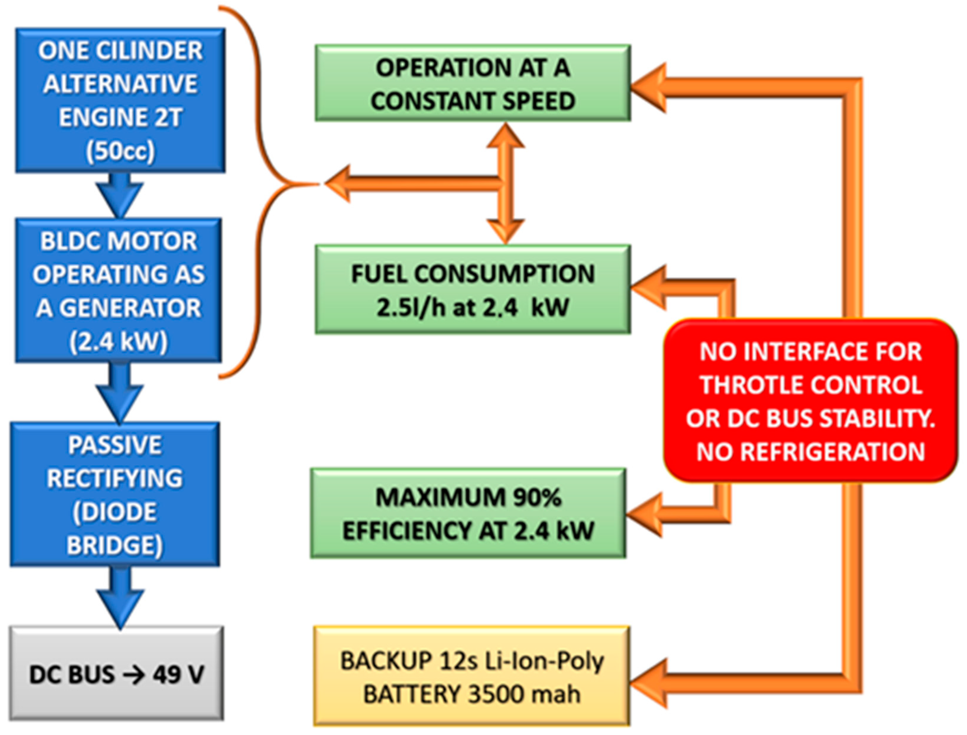
13]. The generator consists of a two-stroke gasoline motor, directly coupled to a Brushless DC motor (BLDC) operating as a generator. The system includes a control unit—in essence, a three-phase diode rectifier—a battery backup in case of fault of the ICU and an optional 433 MHz monitoring system to check the fuel level during flight.
Figure 4 shows that the design of NOVA is practical and valuable, with the aim of maximum simplicity, but it presents some drawbacks that we attempt to solve in our prototype and that are presented below. The operation of the internal combustion engine at a constant speed—quite likely at full throttle—and maximum power dramatically simplifies the electronic design but leads to quite a few negative aspects. When the aircraft does not need the maximum current to power its propulsion motors, the engine is still running at its highest speed, producing higher fuel consumption and leading to the heating and wear of mechanical components. If the lack of a refrigeration system is added into consideration, and the fact that the ventilation provided during the flight may be zero, depending on the type of operation, the only response must be to limit flight times and to carry out maintenance work more regularly. In fact, during our contacts with the company, we were informed that the generator was not designed—or even tested—for flights longer than 3 h, since no refrigeration system—neither a water nor an air cooling system—was available.
The review of other products extended to commercially available systems continues with two H-UAS manufactured in Spain (Quaternium HYBRIX™ and Aerocámaras AEROHYB™) and the hybrid generator from the Canadian company Pegasus Aeronautics known as GE70™, whose design is relatively similar to our prototype.
HYBRIX [
16], was presented in 2016. Version 1.0 used a high-capacity 12S LiPo battery parallel-connected to a hybrid generator consisting of a small displacement two-stroke engine and a BLDC generator. It was probably the first H-UAS ever presented in Europe. However, the first units we could review used a very ineffective belt transmission between the engine and the generator, and propulsion motors were Hengli™ low-cost motors that could hardly fulfil the specifications of Quaternium™, (46510 Valencia, Spain). Version 1.2 seems to have been drastically changed, with the design of a more sophisticated and efficient hybrid generator; however, according to its specifications, its output power is only 2.6 kW [
17].
In the same way that GAIA struggles due to presenting low thrust vs. weight ratio, this aircraft with only four rotors faces a difficult situation when flying with its MTOW. If the power generated is divided between four propulsion motors, the maximum available power per motor is 650 W. Although a cell having only four motors reduces weight and facilitates transport, it also increases power consumption and decreases stability. It is well known [
18], that a BLDC’s specific power (ratio of output power vs. weight) increases with power reduction. Therefore, splitting the propulsion system into a higher number of motors will reduce consumption and increase efficiency. Moreover, fault-tolerant autopilots cannot be used in a four-motor frame, as a motor fault cannot be compensated by the other three motors.
No data are available about the voltage generated by this hybrid unit. Nevertheless, the analysis of its thrust vs. weight ratio can be easily conducted. For an MTOW of 25 kg and assuming a ratio of 1:1, every motor must produce a thrust of 6250 g with a maximum input power of 650 W. The selected propellers are from 30 to 32” in order to use low-kV motors and thus reduce power consumption. If the g per watt (gr/W) efficiency that the motors must fulfil is calculated, the obtained value is rounded to 10 g/W.
Although Quaternium™ does not identify the installed motors, they seem to be T-MOTORS™. A complete review of the catalogue of the motor’s manufacturer did not allow the authors to find any product capable of reaching such a high efficiency unless the motor were driven at an extremely low RPM.
Table 1 shows the datasheet of the aircraft, as presented on the manufacturer’s website [
16]:
It is quite likely that an increase in the weight vs. thrust ratio might be achieved in the UAS by using a voltage below the usual 48–50 V of 12S batteries combined with high-diameter propellers. This hypothesis is based on the fact that high-efficiency T-Motors are not designed to operate with 30” or 32” propellers. Nevertheless, HYBRIX’s datasheet, as well as others from other companies, must be read with caution. Since no standards exist for UAS product specifications, companies tend to show maximum values for all the variables, although they cannot be fulfilled simultaneously. For instance, an 80 km/h speed is possible without a payload but physically unreachable when flying with the MTOW.
Aerocámaras (Lalín, Pontevedra-Spain) AEROHYB™ [
19], is assembled in Spain. It uses a light commercial frame, a T-MOTORS propulsion system, a DJI A3PRO™, Lightbridge 2™ and a NOVA2400™ hybrid generator. The maximum payload is 5 kg. Although no data are available, the extremely slim and apparently light frame result in an empty weight that is lower than GAIA2400™. This weight reduction will increase the thrust vs. weight ratio, and longer and more stable flights with greater manoeuvrability would be possible. However, its operation for 7 h is far from advisable, since the generator’s manufacturer did not test it for more than 3 h because of heating concerns. Moreover, a 7 h flight implies the use of 17.5 L of fuel. If gasoline density (0.755 kg/L) is used to calculate fuel weight, the calculated weight is 13 kg, which added to the maximum payload (5 kg) gives a final weight of 18 kg (not including the frame and propulsion). Under these conditions, the MTOW of the aircraft will very likely be 25 kg, and the thrust vs. weight ratio will again be extremely poor.
Both in this case and the case of Quaternium™, impressive flight time records have been presented. Although there is no doubt that these flight times have truly been obtained, they must not mislead customers. Using a very large fuel tank and taking off at the limit of a thrust vs. weight ratio slightly higher than 1 does not mean that operational flight is possible. If there is no manoeuvrability, flying above the mean sea level will be impossible, and even very low wind speed will prevent flight.
One of the seemingly more advanced and efficient hybrid generators is GE70™ from Pegasus Aeronautics [
20]. Its design is compact and similar to our prototype. The BLDC generator has been installed, at least in the latest versions, inside a two-stroke two-cylinder carter of a 70 cc engine [
21]. The engine is a Desert Aircraft DA-70 [
22], whose power, at slightly above 5 kW, seems to the authors to be low for operation over medium- or long-term periods under the maximum output power of 4 kW.
Table 2 shows the product’s specifications.
Although GE70 was presented to the press, some unknown variables exist in its specifications that could not be clarified even after contacting Pegasus Aeronautics. The overall base weight only includes the weight of the engine and generator. The pumping system, electronic control and heat exchanger are not included. The installation of the BLDC generator inside the crankcase is extremely close to the combustion chambers and shares space with the engine shaft. Sharing a heat-conducting component increases the temperature, and therefore the permanent magnets work at higher temperatures. The hysteresis cycle (flux density vs. magnetic density curve) narrows with temperature [
23], strongly reducing the flux density, to the point that at very high temperatures (Curie’s temperature), demagnetization occurs.
The generator’s maximum operating temperature should not, therefore, surpass 70 °C. Considering the extremely compact design, keeping the magnets at 70 °C only seems to be possible if the crankcase were at the same temperature. Neglecting the need for a special design and selection of materials for the engine, to the best of the authors’ knowledge, a thermal problem exists; keeping both the optimal temperature for the cylinder head to get the best efficiency of fuel combustion and the magnets cool to not reduce their flux density seems impossible. In fact, its designers affirm that they worked with the engine’s most efficient temperature [
24]: “You can mount the radiator anywhere, and this approach has really paid off because we can maintain the ideal cylinder head temperature regardless of load, ambient conditions and altitude [
24]”. The system uses a 12S battery. If 50 V is the output voltage, the control system operation is, in our opinion, somewhat contradictory: “Pegasus is such that the DC output from the GCU does not have to be directly proportional to power input from the generator” and “There is a small battery in parallel with the electric generator unit to provide supplementary power to cope with occasional transient demands during the flight [
24]”.
To end this introduction and review, it is necessary to mention the first H-UAS presented worldwide: TAILWIND from Skyfront™, Edison Way, Menlo Park California. Skyfront was founded in 2013, and in 2016 they produced TAILWIND, which began its distribution around the end of 2017. TAILWIND [
25], is a small four-rotor H-UAS with an efficient and simple design for large autonomous flights with low-weight payloads. Since the success of their first product, the company has developed other aircrafts such as PERMITER-4™ and PERMITER-8™ [
26]. The design of the cells to be much lighter and smaller, the high number of small propulsion motors and the maximum payloads used by this manufacturer confirm the authors’ previous review; for low-weight payloads, no problem exists. In the next section, a thorough description of our prototype is presented, showing the preliminary results.
2. Materials and Methods
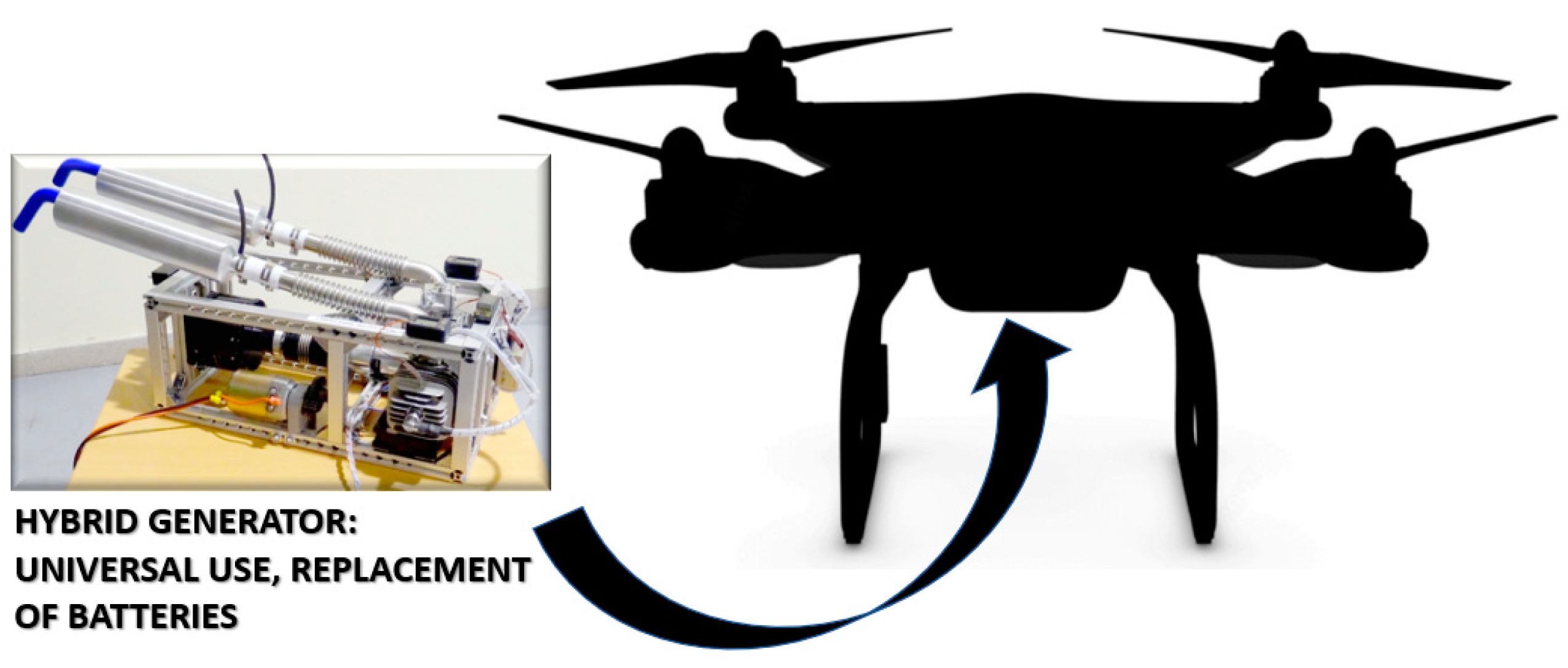
Before presenting the architecture of the designed prototype, it is necessary to point out that our aim is for the device to be universally used as the replacement for the set of batteries for any UAS, in the same way as other generators. Its differences lie in its higher power, at twice the maximum of the largest hybrid generator, and in the number of additional functions its novel electronic design provides. However, although an FPGA with numerous control loops manages the whole system, it must also be analysed as a power source that replaces the battery, as graphically shown in
Figure 5. Flight control algorithms have not been programmed in the FPGA. Although its implementation would allow the use of advanced control strategies regarding system uncertainty [
27,
28], thus reaching an optimal result, the great complexity of integrating flight control algorithms with the management of energy, as well as the electronic speed controllers (ESCs) and propulsion motors, would give rise to an entire H-UAS instead of a universal hybrid power source.
Figure 6 shows a diagram of the system’s simplified architecture. The three-phase voltage generated by the BLDC generator is actively rectified and filtered. The obtained output DC variable voltage (the engine works at a variable RPM) is the input for a synchronous boost converter that is controlled by the FPGA. Thus, a stable DC voltage is used to power the UAS’ flight controller, the propulsion motors’ ESCs and any other on-board electronic device. In the DC bus, an SC array and two-way converter are also connected. A second control loop of the FPGA manages the charging and discharging of the stored energy. When a sudden demand for power because of any external action or perturbation is detected, the SCs provide enough energy to keep the DC bus stable during the time of acceleration of the ICU. Once the power demand is reduced, the aforementioned control loop re-initiates the charging of the SCs. The throttle and the cooling system control, also managed by the FPGA, are not included in the figure.
A more detailed graph with the FPGA, as the core of the hybrid generator, is shown in
Figure 7. Although at first glance
Figure 7 might seem complex, a colour code has been used to facilitate the reader’s analysis of the system. The ICU, BLDC generator and SC array are presented in orange, a black–grey gradient and green, respectively. AC/DC and DC/DC converters for the output DC bus are shown in blue. Control, monitoring and data transmission are managed by the FPGA, which is represented within a red rectangle in the centre. Algorithms and their connections with the different pieces of hardware are shown in yellow. Actions are described inside white boxes. Air-forced ventilation for the ICU is shown in grey, and data sent to a land On-Screen-Display (OSD) system by an XBEE™ SX868 long-range 433 MHz module are shown in purple. The intricate paths of red lines show that the overall system is fully controlled by the FPGA, which receives sensors’ inputs and establishes the converters’ points of operation that give rise to a combination of throttle level and duty cycles suitable for the flight envelope. The flight envelope can be selected by the pilot by defining the maximum level of throttle variation, when required by flight conditions, or automatically adapted by reducing the engine’s RPM to produce only the instantaneous energy needed. The variable regimen of the ICU, on a wide range, reduces heating and fuel consumption. The task of the SC array, as explained below, is to provide the necessary energy to allow the engine to accelerate instantaneously. The slow response of the ICU, in combination with the inertia momentum, does not allow the generation of maximum power if a sharp action of the pilot is performed or the aircraft needs additional power to compensate for gusts of wind.
Table 3 shows the main specifications of the prototype.
As shown in
Table 3, significant differences exist between the designed prototype and the systems reviewed in the introduction: active rectifying, a digitally controlled DC/DC converter, air-forced adjustable ventilation, a much higher output power, the replacement of backup batteries by a SCs capacitors array and four control loops, all of which are integrated in the same FPGA.
Since SCs are quite new technology and quickly evolving, before explaining the operating principle of the prototype, it is necessary to briefly describe their properties. Supercapacitors, unlike batteries, do not store and release energy through chemical reactions but rather directly accumulate electrical charges, retaining energy in the form of an electrical field. Their main disadvantage, compared to batteries, is that the amount of energy they store is lower. In the case of Li-Ion batteries, the energy density ranges between 100 and 250 Wh/kg, while in current SCs, this value is around 4–6 Wh/kg, although this situation is changing with the recent emergence of graphene SCs, whose energy density is around 110–115 Wh/kg. The main advantage of SCs is their low equivalent series resistance (ESR), which allows them to handle high power with an excellent performance and very low heating. In addition to this, the number of use cycles of SCs can reach millions under standard conditions—well above any battery—and their recycling or waste disposal does not present any drawback.
The use of SCs is especially suitable in applications that involve numerous charge and discharge cycles in which high power is handled. For this reason, they are usually combined in hybrid industrial applications with other energy storage systems with higher energy density but slower dynamics.
Although a more detailed description of every piece of hardware, as well as preliminary results, is presented in the next subsections, the general operating principle of the prototype is as follows: the ICU and BLDC generator are linked with a low-weight high-precision flexible coupling. The ICU, because of its extremely high specific power, is started by means of an external small DC motor. A clutch system is also used for this purpose, releasing the ICU’s shaft as soon as it is started. The variable-frequency AC output voltage generated by the BLDC generator is actively rectified. Very low-internal-resistance MOSFETs (3 mΩ), in a three-branch parallel configuration (1 mΩ), replace diodes and transistors. They are triggered from the FPGA, with an accurate delay, to obtain the optimal commutation point. Thus, losses are reduced a great deal, as well as the weight of the rectifier. A DC/DC boost converter is connected downstream to the active rectifier. Active rectifying is also used in the converter, reaching efficiencies that vary from 91.2% to 95% depending on the ICU RPM.
The converter’s point of operation is also controlled by the FPGA. The charging of the SC array is under its control as well. When the flying envelope implies a low power profile, the control system decreases the ICU RPM, reducing fuel consumption, motor wear and heating. The time between inspection and service stops is therefore increased. Forced ventilation is also adjusted to keep cylinders at optimal temperature. Another control loop implemented in the FPGA adjusts the airflow to maintain a constant temperature. If a sudden manoeuvre is performed by the pilot or an external perturbation occurs, such as a strong gust of wind, the slow response of the ICU to provide the new additional power is dampened by using the energy stored in the capacitors array. Once flight conditions demand less energy, the FPGA activates the two-way converter to recharge the SCs. This process continues during the whole flight. The charging of SCs can be done extremely quickly in comparison to batteries, and these devices are capable of operating for a million cycles. The use of a backup battery in case of an ICU fault is not possible if the hybrid generator, as in this case, provides a high output power. Unfortunately, no commercial 12S LiPo batteries exist that are capable of providing 155 A without an unsustainable voltage drop. Moreover, such a battery’s weight would be unacceptable.
More than 300 tests were performed in our lab on all types of Li-Ion polymers and Li-Ion batteries. Only FoxtechFPV’s solid batteries can deliver this level of current. They are only manufactured for large capacities from 16 Ah to 30 Ah. Thus, their use in this application was impossible. Regarding this issue of Li-Ion polymer batteries,
Figure 8 shows the results obtained during a test at 90 A discharge on an 18 Ah 6S battery. The selected manufacturer was the best and most known, GENSACE™ (Genspow GmbH Ottostr.11 41352 Korschenbroich, Germany) [
29]. The tested battery belonged to their third generation of UAS batteries with integrated electronics. A huge voltage drop can be observed in the graph, which clearly prevents its use as a backup system. In fact, after two years of tests on batteries, we could conclude that, for capacities above 12 Ah, the maximum discharge rate, with an acceptable voltage drop and temperature increase, is around 6 °C.
A simple redesign of the power balance in the prototype, increasing stored energy with the generation of SCs and adding a fast charge prior to flight during the heating up of the motor, might provide the pilot with enough energy to perform a safe emergency landing.
The prototype presents two operation modes: the manual selection of the flight envelope, when the pilot decides the maximum level of throttle variation, and adaptative control. The first is included to decrease or even suppress the variation of throttle range for flights under very harsh conditions, such as those at high altitude or with strong winds. The system is completed with a 433 MHZ on-board transmitter. An XBEE™ SX 868 module was selected, since it is low-cost, light, small and long-range. This communication system was installed in the ground control station to receive information about the temperature, fuel consumption and level of charge of the energy storage system by means of an OSD system.
3. Results
This section is divided into five subsections: one per piece of hardware. A detailed description of each component is presented together with the preliminary obtained results.
Every piece of equipment was first simulated using Mathworks-Simulink™ and Pspice™ and then prototyped, and some of them were then sent to manufacturing. Since our aim is only to present the system’s architecture and preliminary outcomes, some hardware has been completed, other parts have been prototyped and a few have only been simulated. The last subsection presents in depth the global aspect, components and sensors of the prototype, which is already functional when used at full throttle in the same way as NOVA2400™ but produces nearly three times its output power.
3.1. Internal Combustion Unit and Generator
The ICU selected for the prototype was a DLE-111™ twin two-stroke gasoline engine. It was chosen because of its high specific power: 11.3 hp for a final weight slightly higher than 2.5 kg, including ignition and muffler exhaust silencers.
Figure 9 shows the motor, and
Table 4 shows its main specifications.
The engine was modified to improve its reliability and efficiency. After a 15 h breaking-in period, bearings were replaced by high-quality SKF™ products; gaskets were also removed, and the crankcase was carefully sealed. Original sparks were substituted by cooler Iridium NGK CM-6 sparks, thus providing the combustion chamber with a higher capacity for heat dissipation. Muffler exhaust silencers were installed both to reduce noise and increase output power.
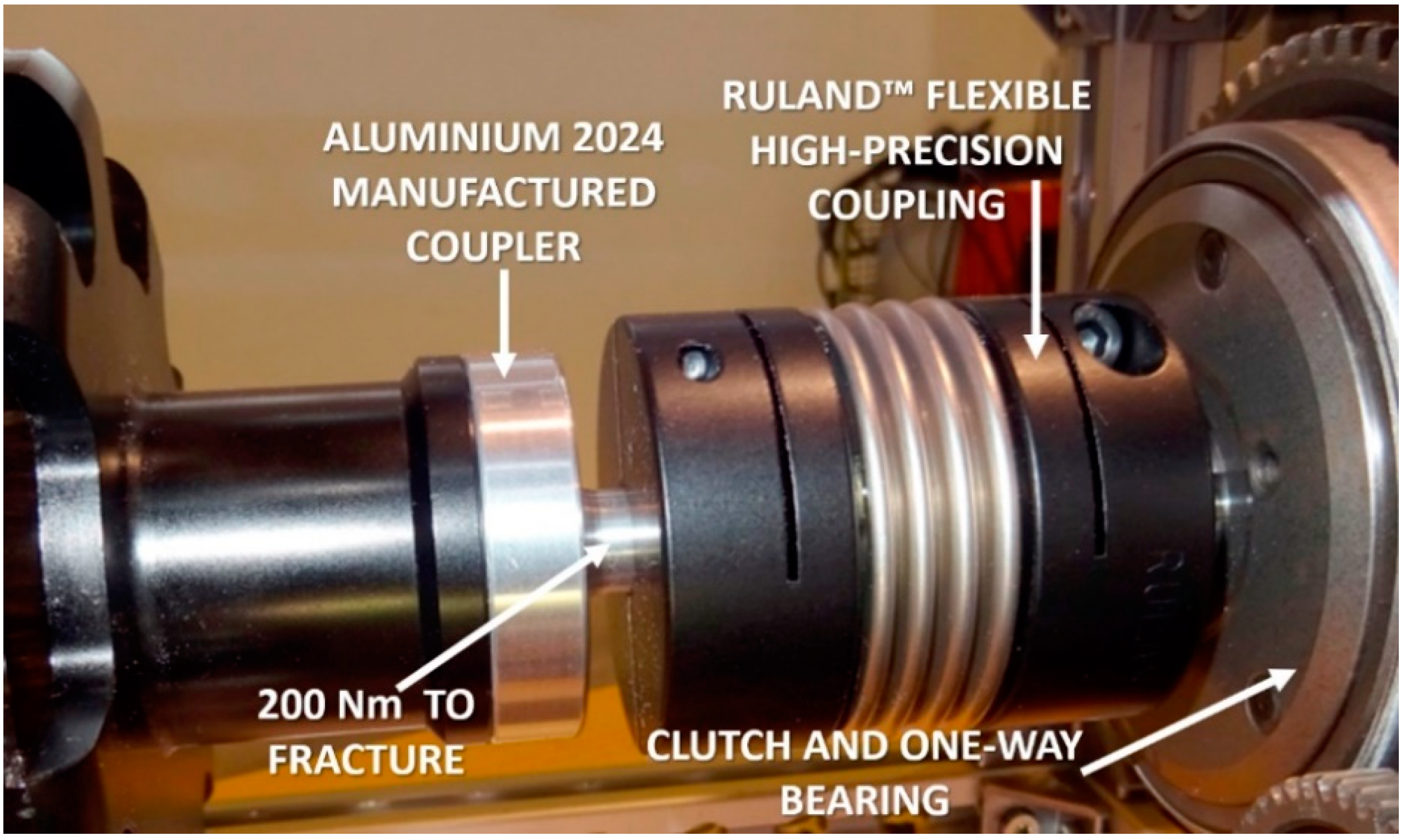
The propeller shaft was cut off, and an aluminium alloy 2024 coupler was CNC manufactured, together with a high-precision, high-torque elastic coupling, to link the ICU and the generator.
The compression ratio in this engine was made very high in order to obtain 11.2 hp output power. For this reason, the start-up of the motor is harsh, and self-starting had to be discarded. The torque of this type of engine presents strong oscillations depending on the crankshaft position, which are damped in its use as a hybrid generator by the BLDC generator inertia. However, the maximum start-up torque was calculated as 115 Nm. Therefore, an external removable 12 V DC motor, in combination with a clutch and a one-direction bearing, was installed. A small two-stage gearbox was attached to the bench, and the final gear ratio was calculated to obtain a start-up that did not take more than 2 s.
Figure 10 shows the clutch and one-way bearing.
The DC motor torque is multiplied by the gearbox, and the clutch, together with the one-way bearing, easily moves at quite a high speed of the motor’s shaft during start-up. Once the engine has started, its faster rotating motion releases the clutch, and the DC starter can be removed.
Starting the engine in this machine was so difficult that, even with the largest starter for giant-scale RC planes acting on a cone installed on the motor shaft, it was impossible to produce a single rotation of the shaft. This type of engine, with an extremely high specific power, is intended to be manually started by using a glove and pulling on one propeller blade. Before the solution of the clutch and the one-way bearing was found, trapezoidal belts and even chains were unsuccessfully tested. Therefore, it is the authors’ opinion that the mechanical start-up system may be useful for other researchers who aim to increase the power of their hybrid generators, or even for the use of this type of engine in fixed-wing UAS.
The BLDC generator was a ROTOMAX 150 cc™, which is so called because it was designed to produce an output power equivalent to an engine of 150 cc displacement.
Figure 11 shows a photograph of the motor, and
Table 5 shows its specifications. Regarding
Table 5, some non-available data were obtained in our test bench of electric motors or measured with laboratory instrumentation.
This motor was selected because its speed constant kV fitted best with the engine specifications. Its design is excellent, and it features slots in the stator with chamfered edges to improve ventilation. Bearings and their housings are designed to endure the axial force produced by the traction of a propeller; thus, they provide additional mechanical strength, since those forces does not exist in the prototype. The engine and the generator are separated, and the former uses two adjustable speed fans for its cooling; therefore, the problems caused by a temperature increase in the permanent magnets, as exhibited by the Pegasus GE70™, do not exist.
A review of the motor’s specifications shows that it was overdimensioned for our prototype. The maximum electrical power might reach 8.4 kW, but it was reduced to 7.75 kW. This power reduction decreased the heating of the motor and was done to generate maximum power at the point of maximum efficiency: 86% at 150 A. Thus, both the ICU and BLDC generator worked below their limits and at their best-efficiency operating points.
Another reason for the selection of this motor was its high number of poles. An AC-generated voltage increases its frequency with the number of poles, thus reducing the need to filter voltage ripple at the output DC bus (rectifier output). A very small and low-capacity electrolytic capacitor is sufficient to practically obtain a flat, rectified voltage.
The generator’s weight was low, and its dimensions were suitable for a prototype. A further development of the system, focused on industrial manufacturing, will require the motor to be redesigned to reduce its weight, decrease its length and increase its diameter. As referred to above, as the shaft suffers only a torsional stress in this application, reinforcement parts might also be detached.
Figure 12 and
Figure 13 show the excellent behaviour of the BLDC generator. In
Figure 12, line voltages with the generator rotating at 6156 RPM are presented. The frequency of the AC voltage is 1026 Hz and waveforms are practically sinusoidal.
Figure 13 shows the rectified voltage without filtering. It can be clearly seen that the high number of poles produces a quasi-sinusoidal waveform and the voltage ripple presents a frequency higher than 1 kHz; thus, it can be supressed with a very low-capacitance electrolytic capacitor.
3.2. Active Rectifier
The use of diodes leads to two complex drawbacks: (1) the voltage drop of nearly 3 V in the pair of conducting diodes is not affordable without affecting the system’s overall performance, and (2) power losses in the diodes can reach values above 450 W for an output current of 150 A. Moreover, the weight of a three-phase diode rectifier is not negligible.
For all the above reasons, the use of active rectifiers built with parallelized surface-mounted devices (SMDs) with extremely low channel resistances reduces the total voltage drop to below 0.5 V and dissipates the power to less than 1/10th of the power losses of conventional diodes.
Figure 14 shows a diagram in which the voltage drop in conductive diodes is presented. The replacement of diodes by low channel resistance MOSFETs, parallelized in three branches, yields a final resistance of 1 mΩ and a voltage drop of 0.3 V in our prototype, with transistors conducting at 150 A.
Active or synchronous rectifying (SR) is a technique that is widely used to reduce the losses in the rectification process. As is well known, the diodes are replaced by MOSFETs in order to reduce the losses. This might seem to be an old-fashioned technique if it were applied as it was originally developed; the control signals were obtained by means of a transformer, and thus they are delayed with respect to the optimal commutation point. This problem arises because they begin conduction when the current in the rectifier is already flowing. In our prototype, taking advantage of the FPGA, a specific algorithm has been developed in such a way that the control signals are generated in advance. Therefore, the approach to SR is essentially different, and the previous drawbacks are overcome.
The algorithm implemented in the FPGA measures the time at every single cycle and produces the control waveform accordingly. Considering the size and weight of the FPGA, its integration in the prototype even reduces the weight and volume while adding more control blocks for the other functions of the system. The use of microcontrollers and microprocessors in power electronics is quite usual. FPGAs are now replacing these components, since they are faster, and several control systems can be provided with a single chip [
30].
In hybrid generators, the output voltage is low, while the current is medium to high. For instance, a small 2.4 kW unit operating at 50 V must deliver nearly 50 A. Therefore, if a DC/DC converter is used to control throttle, the converter requires active/synchronous rectification as well [
31]. It must be underlined that this strategy is used in different topologies for different applications [
32], but always with the goal of improving the efficiency. On the other hand, the replacement of diodes by MOSFETs implies the generation of gate-driving signals; these can be obtained in most cases by means of additional windings [
33], which is only possible by adding magnetic elements. In some applications, the adjustment of the gate-signals is necessary only to prevent short-circuit situations and ensure adequate behaviour under different operating conditions [
34]. Generating gate-driving signals without magnetic components is a complex process. However, when correctly done, losses during rectification or conversion are negligible, and almost no voltage drop is exhibited.
Figure 15 shows the selected device for the prototype. The FPGA is much smaller than the board presented in the figure, which includes a development system.
Control is programmed using Cadence™ 9.2.3 software. Gate-driving signals and control algorithms for both the rectifier and DC/DC converter have been programmed and tested. The rectifier and converter boards have been prototyped. The former is pending manufacturing, and the latter needs additional tests and a redesign of the inductor. Photographs of the prototyped PCBs are shown in the next figures.
The management of the SC array has not been addressed yet. However, dimensioning and simulation has been done by means of Mathworks-Simulink™ and is presented in
Section 3.4. As a summary of the functions developed for the FPGA,
Table 6 shows its control and monitoring algorithms.
To reach the optimal commutation point of the MOSFETs, the gate-signals must be slightly advanced. The process used to reach the exact advance time consisted of simulating the system and finding the exact time by means of a test-error method. The FPGA was then programmed, and the MOSFETs’ commutations were checked in the prototyped boards. Simulations were carried out with Quartus II™ software, observing that the desired advance on the opening signals delivered by FPGA was obtained. Thus, the lag produced by electronic devices was suppressed, and the MOSFETs’ commutations were optimal. The designed active rectifier presented an efficiency higher than 98%.
If diodes had been used, the voltage drop would have meant a 6% reduction in bus voltage and a power loss of 6.25%, affecting the propulsion system supply. Moreover, the weight would have increased by 100 g, since a three-phase diode rectifier weighs between 150 and 180 g, in comparison with the 40–50 g of the active rectifier including the FPGA.
Figure 16 shows the FPGA gate signals. The advanced signal (orange) is compared to the waveform produced by a digital signal generator. The complexity of reaching an optimal commutation can be clearly appreciated.
3.3. DC/DC Converter Synchronous Boost Converter
Taking into account the restrictions imposed on a hybrid generator, the topology of the DC/DC converter had to be as simple as possible and include the minimum number of magnetic components in order to reduce weight. For this reason, a boost converter was used. The conventional topology of a boost converter uses inductance, a MOSFET commutating in the range of kHz, a diode and a filtering capacitor. Increasing the commutation frequency decreases both the filtering capacity and inductance. However, very high frequencies complicate or prevent the design of the converter because of parasitic effects such as leakage reactance. Consequently, a value of 50 kHz was chosen in order to reach a balance between design complexity and weight.
More sophisticated resonant topologies might seem to be an attractive solution, since it is possible to increase the frequency without compromising the efficiency. However, when operating with high levels of current, the capacitors must be able to withstand high voltages, which implies the use of bulky capacitors. A simple calculation can be made to show the problem. At an output current of 100 A, which implies values for the resonant current of around 150 A, a switching frequency of 100 kHz and a capacity of 100 nFm, the voltage in the resonant capacitor exceeds 2 kV.
For a high-current output, such as 150 A, the presence of the diode produces the same undesirable effects described for the rectifier. Therefore, active rectifying was also applied to the converter, and the diode was replaced by three parallelized low-resistance MOSFETs. With this topology, first in simulation and then with a simple prototyped PCB, the reached efficiencies varied from 91% to 95% depending on the DC-bus voltage values or the ICU throttle. A study was carried out enforcing maximum throttle variation, and 91% efficiency was obtained when the ICU was running at idle RPM. An efficiency of 95% was reached for the output of 150 A, where the efficiency of the generator was at maximum.
Although some PCBs have been dismounted and the rectifier sent for manufacturing,
Figure 17 shows some PCBs and the SMD design sent for manufacturing.
Figure 18 presents the first SMD prototype of the active rectifier.
Figure 19 shows the result of a test in which the voltage control loop of the prototype converter was closed. The graph is presented to show that, even with an unfinished prototype, the DC bus presents a very low voltage ripple, at around 250 mV—0.5% of the maximum voltage.
3.4. Energy Storage System: SC Array Dimensioning and Operation
The array of capacitors was dimensioned and simulated. The dimensioning procedure was the result of previous studies in this field done by our research group [
35,
36,
37]. A thorough Simulink™ model was developed, and the cells were selected to obtain the calculated energy with the minimum weight. The SC array was calculated to allow the engine to accelerate from 3500 RMP to 7500 RPM without any fluctuation in the DC bus. Although the acceleration process took around 1.5 s, the storage energy system was oversized to maintain a constant voltage for 3 s. The SC array needed to provide 3750 W. The following allows the calculation of the discharge time when the SCs are operated at a constant power:
where
P is the discharged power,
is the initial internal voltage of SC array (50 V),
and
are the equivalent resistance and capacitance, respectively, and
is the minimum voltage the SC array can reach:
With this method, all the possible combinations were studied; furthermore, the weight and volume of all of the combinations were also calculated. The result led to the selection of the used SC cell: a Maxwell™ 150F in an arrangement of two parallel branches of 18 series-connected cells.
Table 7 shows the result of the study and the different options that were analysed.
Figure 20 shows a diagram of the SC array as it was built. The 18 series-connected cells as well as the parallel branches are represented. Its dimensions were very small, allowing it to be attached to the bottom of the bench where the whole system was installed. The weight of the array, already included in the dry weight of the system provided in
Table 3, was 1044 g.
Costs were not included in the study, although SCs are relatively expensive. The selected cell was the one that formed the array with the minimum weight and volume. Prices change with the number of ordered cells. In our case, where the order was of 50 units, extra cells were used compared with previous research, and the price of the SC array was EUR 864.
As with all the other parts of the prototype, the SC array and the two-way converter, which managed the stored energy under the control of the FPGA, were simulated using Simulink™. The simulation model presented different levels for electrical and thermal analysis, as validated in [
35,
36,
37]. The SCs’ internal resistance and temperature were inputted into the model in order to analyse the behaviour of different types of SCs with different specifications. The model of the SCs was placed inside a very simple bi-directional electronic converter. The electronic devices of the converter were identical to those used in the actual SMD board installed in the SC array and controlled from the FPGA. The converter operated in closed-loop mode by simply using a PI controller.
Figure 21 and
Figure 22 show the simulation model.
Figure 23 is presented to show the correct behaviour of the system. For the sake of simplicity, only the evolution of voltage and current in the SC array is presented. The simulation began with the array fully charged at 50 V. For approximately 3 s, it was discharged, delivering 100 A. When the voltage was slightly below 30 V, a charge process at a constant current of 100 A began that lasted 1 s. The voltage accordingly increased in this period. When the SC array’s energy is used to reduce the throttle of the engine, the charging process will, obviously, be different. The UAS will take off with the SC array fully charged, and the throttle will be reduced as soon as possible. When additional energy is needed to stabilize the DC bus, the discharge of the SC array will provide a high value of current. Since the time of acceleration is shorter than the time that the energy stored in the SC array is able to keep the bus stable, it will never reach a full discharge level. Nevertheless, throttle control will keep the engine at maximum RPM, even if the power demand is not at maximum, until the SC array is fully recharged.
3.5. MHz Radio Link for Monitoring
In this section, the level of development of the OSD system for on-line monitoring is very briefly presented. XBEE™ SX 868 433 MHz modules have been successfully tested and have shown excellent behaviour as long-range radio links in the range of distances admitted by the EASA for UAS operation. Since a set of Python libraries exists for their communication, the system showed in
Figure 24 is being developed.
As presented in the figure, the system consists of a LCD tactile display and the XBEE receiver. The graphical interface has been designed, and it is operative. The on-board transmitter receives data from the FPGA, and it is our aim to reach a final system that is capable of changing parameters on-line according to the flight envelope, with full or variable throttle, from the LCD.
3.6. Complete Prototype
All the pieces of hardware described above were mounted on a manually built bench made with pre-formed aluminium profiles. Although it will be redesigned, profiles were used to determine the maximum dry weight. The result was promising, since even with all the limitations created by the use of commercial products and manual manufacturing, the obtained weight, including electronics, was 9.2 kg.
The ICU and the BLDC generator were attached to the aluminium cage through the holders prepared in their enclosures for installation in an aircraft. The shaft of the ICU was cut off, and two aluminium alloy 2024 couplers were CNC manufactured to link both machines by means of a flexible coupling. The cage, carefully mounted, allowed an almost-perfect alignment to be made. The motor was fixed to four aluminium profiles, and it was slid until the shafts of the couplers were aligned and touched one another. The ICU was then firmly screwed with self-locking nuts and slid back again to install the flexible coupling.
The aluminium coupler attached to the ICU passes through the clutch and one-way bearing. A small two-stage gearbox was installed in one of the sides of the bench. Thus, the DC detachable starter only needs to be inserted in a cylindrical hole to engage the start-up system.
It was our goal for the starter to be connected to a car battery and to be removed as soon as the motor starts. It is not necessary to remove it for land tests, since the clutch and the one-way bearing decouple the entire start-up system.
Figure 25 shows the bench fully mounted with the muffler exhausts.
Special attention was paid to the coupling of the ICU and the BLDC generator for two reasons: (1) misalignment is one the main causes of vibration, and (2) the system is designed to be used with very strong throttle variations. Flexible aluminium with a perfectly balanced coupling capable of withstanding more than twice the maximum torque and a rotating speed of 10,000 RPM reduces vibration and damps the transient speed variations. For this reason, a Ruland™ high-torque coupling was chosen.
Figure 26 shows the main features of the coupling.
Figure 27 presents a detailed view of the link between the ICU and the BLDC generator. Although the photograph does not show it, aluminium couplers were attached to both machines by means of six M5 screws. The diameter of the shaft inserted in the coupling and the dimensions of its internal bore were selected taking into account the mechanical properties of the aluminium alloy 2024. The transversal section of the shaft was calculated to endure a shear stress equivalent to a 200 Nm torsional torque. Such a high value was possible since aeronautical aluminium, such as that used in this application, presents an elasticity module equivalent to that of carbon steel.
In
Figure 25, other elements of the system can also be observed. Below the two gaskets’ radiators, two electronically controlled fans were installed to provide refrigeration and maintain a suitable temperature on both cylinders. They turned at different RPMs depending on the measured temperature, which fluctuated with environmental and flight conditions as well the throttle level. The temperature was measured by two probes connected to two small LCD displays and sent to the FPGA, which measured temperature and controlled refrigeration.
Although it is the authors’ aim to replace the carburettor with an injection system in a further development, throttle control is achieved by acting on the carburettor’s lever. To achieve this, a high-speed, high-torque titanium gear servo is used.
The movement of the servo is transmitted to the lever by means of a carbon fibre pushrod with ball joints; thus, no slack exists and the movement is very accurate. A 2.4 GHz-FHSS receiver was installed for land testing at different throttle levels and with sudden fluctuations sent from a RC transmitter.
Figure 28 shows this system.


 ,
, 


