Article

Porous Gas Journal Bearings: An Exact Solution Revisited and Force Coefficients for Stable Rotordynamic Performance

1
J. Mike Walker ’66 Department of Mechanical Engineering, Texas A&M University, College Station, TX 77843, USA
2
New Way Air Bearings, Aston, PA 19014, USA
*
Author to whom correspondence should be addressed.
Appl. Sci. 2021, 11(17), 7949; https://doi.org/10.3390/app11177949
Submission received: 5 July 2021 / Revised: 24 August 2021 / Accepted: 26 August 2021 / Published: 28 August 2021
(This article belongs to the Special Issue Gas Bearings: Modelling, Design and Applications)

Abstract

:
Having come of age, gas film bearings enable high-speed oil-free (micro) rotating machinery with gains in efficiency and reliability, longer maintenance intervals, and a reduction in contaminants released to the atmosphere. Among gas bearing types, porous surface gas bearings (PGBs) have proven successful for 50+ years and presently are off-the-shelf mechanical elements. This paper reviews the literature on PGBs since the 1970s and reproduces an exact solution for the performance of cylindrical PGBs. Both the analytical model and an accompanying finite-element (FE) model predict the performance for two PGBs, a commercially available 76 mm diameter bearing and a smaller 25 mm diameter laboratory unit whose experimental performance is available. As expected, the FE model results reproduce the analytical predictions obtained in a minuscule computing time. For a set external supply pressure, as the radial clearance increases, the flow rate through the bearing grows until reaching a peak magnitude. The PGB load capacity is a fraction of the product of the set pressure difference (pS − pa) and the bearing projected area with a significantly large centering static stiffness evolving over a narrow region of clearances. Operation with shaft speed enhances the bearing load capacity; however, at sufficiently high speeds, significant magnitude cross-coupled forces limit the stable operation of a PGB. At constant operating shaft speed, as the whirl frequency grows, the bearing effective stiffness (Keff) increases, while the effective damping (Ceff) becomes positive for whirl frequencies greater than 50% shaft speed. Similar to a plain hydrodynamic journal bearing, the PGB is prone to a half-frequency whirl, albeit the system natural frequency can be high, mainly depending on the external supply pressure. In essence, for the cases considered, PGBs are linear mechanical elements whose load capacity is proportional to the journal eccentricity.

1. Introduction

Gas bearings support oil-free high-speed turbomachinery with significant savings in drag power losses and a reduction in system footprint [1]. Bearings constructed with a layer of porous material offer an alternative to other bearing types, such as orifice compensated bearings and foil bearings [2]. Porous surface gas bearings (PGBs) are commercially available for industrial use, in particular in linear guide systems and in the health imaging industry [3].
The contemporary approach to the modeling of PGBs relies on the numerical solution of the flow equations, using to advantage desktop computational resources [4]. However, the expedience in obtaining numerical predictions often dispenses the flow physics, avoids dimensional analysis, and disregards the effects of physical parameters that carry information on limiting solutions. Hence, this paper carefully reviews the abundant published literature on PGBs and recreates elegant theoretical analyses developed in the 1970s. The predictions from the analytical model are compared against those of a computational finite element (FE) model as well as some published experimental results.

2. The Governing Equations for a PGB and Derived Operating Parameters

The performance of PGBs is determined by their geometry (radial clearance c, length L, and diameter D = 2R), the gas physical properties (density ρ and viscosity μ), the magnitudes of supply pressure (pS) and ambient pressure (pa), the porous material permeability coefficient (κ) and the liner radial thickness (tp), and the operating conditions of shaft angular speed (Ω and precessional frequency (ω).
Figure 1 displays a schematic diagram of a cylindrical PGB with the journal spinning with speed Ω. The film thickness is h = (c + eX cosθ + eY sinθ), where (eX, eY) are the components of the journal static eccentricity. Consider an ideal gas with density ρ = p/(RgT), whose temperature T is constant. Then, the film pressure (p) is governed by (Gargiulo, 1979) [5]. A detailed investigation on the influence of non-zero slip flow condition and tangential flow within the porous material is out of scope in the current analysis.
· p   h 3 12 μ p = Ω R 2 ( p h ) x + ( p h ) t + κ 2 μ     t p ( p 2 p S 2 )
where is the vector gradient operator, μ is the gas viscosity, and pS is the pressure of the pressurized gas supplied through the porous layer. The field p is periodic around the bearing circumference, p θ ,   z , t = p θ + 2 π , z , t , and on the axial ends of the bearing p θ ,   1 2 L , t = p θ ,   1 2 L , t = p a .
Note the supplied mass flow rate through the porous material follows Darcy’s law [6,7,8].
m ˙ = ρ μ   κ t p p S p ~ 1 2 1 μ   R g T κ t p p S 2 p 2
Flow unsteadiness, circumferential flow through the porous media, and inertial effects due to the volume in the porous material are not particularly important in modern commercial products such as carbon graphite [3,9,10].
The PGB geometry, porous material properties, and operating conditions combine to produce three fundamental (dimensionless) parameters,
Λ κ = 12 κ t p   c R c 2 ;   Λ Ω = 6 μ   Ω p S R c 2 ;   Λ ω = 12 μ   ω p S R c 2 ,
known as the flow feeding number, the speed number, and the frequency number, respectively. Clearly pS > pa for the pressurized gas to flow through both the porous layer and then through the film clearance to exit at the bearing sides. Most PGBs have a large slenderness ratio, L/D > 1, hence giving enough surface area for the pressure field to produce a significant bearing load.
The ΛΩ aerodynamic effects due to shaft rotation dominate over aerostatic effects (~pS). Similarly, squeeze film effects (high frequency) dominate for Λω > 1. Incidentally, the porosity parameter Λκ relates the flow conductance across the porous layer (κ/tp) to the conductance through the film, which is proportional to (c3/R2).

3. An Appraisal of the Past Literature

The archival literature on PGBs is abundant with a sound beginning in the early 1960s and continuous developments through the 1980s. Only in the 2000s did commercial applications abound, in particular in the flat panel manufacturing industry, semiconductor manufacturing industry, coordinate measuring machines, computed tomography imaging machines, and precision machine tools and spindles [3].
From 1965 to 1967, Sneck et al. publish three seminal papers [6,7,8] to introduce the theoretical framework for the analysis of gas lubricated PGBs. The authors derived analytical solutions for the flow rate and load capacity of PGBs under aerostatic conditions and produced experimental verification for both the load capacity as well as the flow coefficients. The authors noted the importance of surface roughness that modifies the PGB nominal clearance to produce agreement with the measured load and flow. The later reference [8] noted that shaft surface speed aids to increase the load capacity of PGBs and presents ultimate solutions for operation under very large speed numbers (ΛΩ >> 1). Sneck et al. [6,7,8] did not study the effect of frequency on the bearing stiffness coefficients, and altogether ignored damping coefficients.
At about the same time, in 1968, Mori et al. [11,12] developed a similar solution, albeit for an incompressible fluid, and produced predictive formulas for load capacity and gas flow that agreed well with experimental results for finite length PGBs (L/D ~ ½). Both Sneck et al. and Mori et al. found that the PGB load capacity was a fraction of W* = ((pS − pa) × (L D)), i.e., the product of the pressure difference (pS − pa) times the bearing projected area. Having introduced an equivalent clearance for the layer of porous material, cκ = (12 κ tp)1/3, Mori et al. reported a maximum aerostatic load capacity ~(0.7 × W*) for the range (cκ/c) ~ 0.6–1.0; hence, the practical flow feeding number Λκ ~ (R/tp)2 >> 1.
A decade later (1978), Rao and Majumdar [13] presented a perturbation analysis and numerical solution to calculate the stiffness (K) and damping (C) force coefficients of aerostatic PGBs (ΛΩ = 0). The unique predictions showed C < 0 for small frequency numbers (Λω). Interestingly enough, the analysis did not include the volume of the porous material, which, if large enough and under dynamic conditions, traps the gas to produce a pneumatic-hammer effect, i.e., a self-excited instability due to the absence (even negative) of effective damping [14].
Just a year later, in 1979, Gargiulo [5] presented a comprehensive analysis that included both steady-state performance parameters and the dynamic force coefficients via a perturbation analysis that produces analytical expressions as a function of ΛΩ, Λω, and Λκ, and includes the effect of the material porosity volume. For very small porous volumes, Cargiulo [1] reported a hardening bearing stiffness as frequency grows while the damping coefficient decreases steadily. The findings are similar to those for orifice-compensated aerostatic gas bearings, as published by Lund [15] in 1968. Large porous volumes could lead to a negative direct stiffness but not negative damping, in opposition to Rao and Majumdar’s findings [13]. Under hybrid operations, i.e., operation with shaft speed (ΛΩ > 0), the analysis reports cross coupled stiffness and damping coefficients, growing in proportion to the shaft speed until ΛΩ → 10, to then drop for operation at higher shaft speeds. Cargiulo [5] left for the future (the 21st century) the dynamic stability of PGBs operating in a hybrid mode.
In a companion paper, Cargiulo [16] described the outcome of experiments that for the most part validated the theoretical predictions, in particular the PGB load capacity and the direct force coefficients. The test bearing has L = D = 50.4 mm and a porous liner with thickness tp = 6.4 mm and permeability κ = 2.3 × 10⁻⁹ mm2 (cκ = 5.6 μm). The experiments also revealed the onset of unstable behavior characterized by vibrations of the test system at its natural frequency. The tests conducted with various radial clearances, c = 3 to 17 μm, demonstrated that the test aerostatic PGB produced a journal displacement directly proportional to the applied load, even up to the point of journal contact with the porous liner surface. Hybrid operation, i.e., with shaft rotation (ΛΩ > 0), increases the PGB load capacity and its stiffnesses, direct and cross-coupled. Incidentally, the higher the supply pressure, the larger the bearing centering stiffness (and natural frequency), and hence the more likelihood of a PGB to be tailored for dynamically stable operation.
After a long hiatus, in 2006, Miyatake et al. [17] assessed the stability of a rotor supported on PGBs coated with a surface layer that was ~300 times more restrictive than that of the porous media itself. The manufacturing of surface loaded porous materials is a major breakthrough in PGBs, as they practically eliminate the potential for pneumatic hammer; see Otsu et al. [18].
In practice, PGBs are mounted in series with elastomeric supports (o-rings) to add more effective damping, albeit the soft mounts also reduce the system natural frequency. See for example the synopsis by Hwang [14]. Most recently, various publications detail the application of tilting pad PGBs to enable oil-free turbomachinery operating at high speeds; see San Andrés et al. [2,4,19,20] and Feng et al. [21,22,23]. Tilting pad journal bearings effectively eliminate the cross-coupled stiffness coefficient that could easily excite a hydrodynamic instability and thus extend the maximum operating shaft speed of rotor-bearing systems.
At Texas A&M University, since 2015, San Andrés et al. have been conducting measurements of the rotordynamic response of solid rotors supported on carbon-graphite PGBs: one rotor of small diameter (29 mm) and operating at a high shaft angular speed (55 krpm) [19], and another with large diameter (100 mm) and turning at 18 krpm maximum [4,20]. The rotors’ surface speeds (Us = ΩR) equal 82 m/s and 94 m/s, respectively. Rotordynamic tests show stable responses, free of sub synchronous whirl frequencies. Imbalance mass induced synchronous whirl speed rotor motion amplitudes show peak magnitudes while crossing critical speeds largely determined by the pressure (pS) supplied to the bearings. Derived from recorded amplification factors, the system damping ratio is larger than 10%, uncharacteristically high for gas bearing supported rotors. The computational analysis in [4] solves the Reynolds equation and Darcy’s diffusion equation that couple the flow in the PGB film land to that through the porous layer. The model produces force coefficients that agree well with experimentally-derived effective damping and stiffness coefficients and shows that the magnitude of supply pressure (pS), the permeability coefficient (κ), the pad-pivot stiffness, and the assembly clearance affect significantly the performance, static and dynamic, of the test bearings. In addition, just published in 2021, [2] describes an experimental campaign and the results that quantify the force coefficients of a large size, four tilting pad PGB. From dynamic load experiments conducted with shaft speeds at 6 and 9 krpm (32 and 64 m/s surface speed), the identified PGB’s direct stiffness and damping coefficients are practically invariant with excitation frequency (to max 200 Hz), The pads’ pivot compliance largely determines the bearing direct stiffness coefficients. The experiments also reveal that the load capacity of the bearing is mainly aerostatic, mostly determined by the supply pressure and the bearing preload assembly.
Feng at Hunan University leads an extensive research program whose objective is to develop oil-free bearing technologies applicable to high speed rotating machinery. Feng’s group has effectively tackled bump-type foil GBs, metal mesh foil GBs, and most recently, PGBs since 2018. Feng et al. develop computational analyses for tilting pad PGBs [21,22] and cylindrical PGBs [23] and present model validations against their own experimental results as well as those in [20].
Other minor recent computational developments by Bohle [24] and Lawrence and Kemple [25] provide numerical steps toward modeling aerostatic PGBs while ignoring the vast prior literature reviewed above. Li et al.’s recent work on cylindrical PGBs [23] is particularly of notice, since the recorded static load performance of the test PGB agrees with numerical predictions. However, the identified test bearing force coefficients are rather unique since they follow a trend opposite to prior knowledge, both experimental and analytical [5,16]. That is, the PGB direct stiffness coefficient drops with frequency, while the direct damping coefficient increases.
The recent literature from 2018 through 2021 [2,21,24,25] focuses on building complex comprehensive computational tools with model verifications specific to a tailored configuration for oil-free machinery. The literature misses careful dimensional analysis, physical scaling, and dimensionless number representation that could help improve the selection of the numerical method and its validation.
This paper reworks the classical analyses of Gargiulo [5], Sneck [6], and Mori [11] to derive an exact solution for the ultimate flow rate and flow coefficient, static load capacity, and dynamic force coefficients of a generic cylindrical PGB. In the last stage of the analysis, the evaluation of integrals, the current development relies on modern mathematical software capable of symbolic algebra processing. The authors wish the engineering student and neophyte researcher appreciate the art of fundamental physical analysis, while staying for a short time away from the mundane routine of number crunching.

4. A Close Form Solution to the Flow and Dynamic Force Coefficients in a PGB

In reference to Figure 1, consider journal center motions with small amplitude (δeX, δeY) and frequency (ω) about an equilibrium position (eX0, eY0). The film thickness (h) and pressure (p) fields equal the sum of zeroth-order fields (h0, p0) and first-order or perturbed fields (hσ, pσ)|σ = X, Y,
h = h0 + δeX hX eiωt + δeY hY eiωt → p = p0 + δeσ pσ eiωt, σ = X, Y
where hX = cos(θ) and hY = sin(θ). Above, σ = X, Y, i = 1 .
Substituting Equation (4) into the Reynolds Equation (1) produces the zero-order equation for p0
· p 0 h 0 3 12 μ p 0 = Ω R 2 ( p 0 h 0 ) x + κ 2 μ   t p p 0 2 p S 2
and the first-order equation
· h 0 3 12 μ p σ p 0 + p 0 p σ = Ω R 2 ( p 0 h σ + p σ h 0 ) x + i   ω   ( p 0 h σ + p σ h 0 ) · p 0 h 0 2 4 μ h σ · p 0 + κ μ   t p p 0   p σ ( σ   =   X ,   Y )
Following San Andrés [26], the equations above are integrated in a typical finite element (FE) and assembled over the flow domain to produce sets of algebraic (nonlinear) equations for solution of the pressure fields; and subsequent calculation of the PGB reaction force, drag torque and power, and dynamic force coefficients. Details of the FE model are omitted for brevity.
For operation at a centered condition, h0 = c, Equation (5) reduces to
· p 0 2 = 12   κ c 3   t p p 0 2 p S 2
That dispenses with the effects of gas viscosity (μ) and shaft speed (Ω). Let ψ 0 = p 0 2 p S 2 , then Equation (7) reduces to the simple ordinary differential equation,
d 2 d   z ¯ 2 ψ 0 Λ κ   ψ 0 = 0 .
Above, z ¯ = z R with   γ 2 = Λ κ = 3   κ t p   c D c 2 as the feed flow parameter. The solution of Equation (8) with ambient pressure (pa) at the bearing sides z ¯ = ± L D gives
ψ 0 z ¯ = ψ 0 | p   =   p a cosh γ z ¯ cosh γ L D     p 0 z ¯ = p S 2 + p a 2 p S 2 cosh γ z ¯ cosh γ L D .
The mass flow rate ( M ˙ ) supplied to the bearing through the porous layer equals
M ˙ =   m ˙   R   d θ   d z = γ π   c 3 6   μ   tanh γ L D   p S 2 p a 2 R g T .
Note that M ˙ is proportional to κ   c 3 t p , the average gas density ρ * = 1 2 p S + p a R g T , and the pressure difference p S p a . If the bearing clearance (c) is very large (as when there is no shaft inserted in the bearing), then p = pa over the flow domain, and the supplied flow rate is the largest and equal to
M ˙ max c   = 1 2 κ   μ   t p p S 2 p a 2 R g T π   D   L
M ˙ M ˙ max C r = tanh γ L D γ L D .
The ratio of flows is only a function of the bearing geometry and the permeability coefficient (κ), since γ L D = 3 κ t p c L c . Equation (11), known as the flow coefficient for PGBs [6,7], serves to estimate the permeability coefficient (κ) from measurements of the supplied flow ( M ˙ max ) for various supply pressures, as will be shown later.
Incidentally, the shear drag torque (To) and power loss (Ploss) for the laminar flow in a centered journal bearing equal
To = μ ΩR (R/c) (π D L), Ploss = To Ω.
Note that for an air film, the drag friction coefficient f = To/(W* R) << 1.
As the analysis considers small amplitude motions about the centered condition (e = 0), then from p = p 0 +   δ e X   p X +   δ e Y p Y e i   ω   t , deduce
p 2 = p 0 2 + 2   p 0   δ e X p X   + δ e Y p Y     e i   ω   t   ;   ψ = p 2 p S 2 = ψ 0 +   δ e X   ψ X   + δ e Y   ψ Y     e i   ω   t .
Hence, ψ X = 2 p 0 p X ;   ψ Y = 2 p 0 p Y . Presently, for small amplitude motions about e = 0, let
ψ X = ψ X c ( z )   cos θ   + ψ X s ( z )   sin θ ,   ψ Y = ψ Y c ( z )   cos θ   + ψ Y s ( z )   sin θ .
Then, write the first order Equation (6) for the perturbed pressure fields as
d 2   d   z ¯ 2   ψ X c ψ X s   A ψ X c ψ X s   = C 1 cosh γ z ¯ + C 2 ;   d 2   d   z ¯ 2 ψ Y c ψ Y s A T ψ Y c ψ Y s = C 1 cosh γ z ¯ + C 2
where A = 1 + γ 2 + i Λ ¯ ω Λ ¯ Ω Λ ¯ Ω 1 + γ 2 + i Λ ¯ ω , C 1 = i   2 Λ ¯ ω 3   γ 2 2 Λ ¯ Ω ψ a s c 1 cosh γ L D   and   C 2 = i   2 Λ ¯ ω 2 Λ ¯ Ω p S 2 c
with   ψ a s = p a 2 p S 2   , Λ ¯ Ω = 12 μ   Ω 2 p ¯ 0 R 2 c 2 ;   Λ ¯ ω = 24 μ   ω 2 p ¯ 0 R 2 c 2
using average pressure p ¯ 0 = 1 L 0 L p 0   d z . The boundary conditions for the perturbed fields are homogeneous, i.e., ψ X z ¯ = ± L D = ψ Y z ¯ = ± L D = 0 . Then,
ψ X c = ψ Y s =   ψ X s = ψ Y c = 0   at   z ¯ = ± L D   .
Note that Equation (16) reveals that ψ X c = ψ Y s ,   ψ X s = ψ Y c .
Once found, integration of the pressure field (p) acting on the rotor surface gives the bearing reaction force (F) with components
F X F Y = P 0 P a + δ e X   P X +   δ e Y P Y   e i   ω   t cos θ sin θ   R d θ d z .
As the bearing is centered, the zeroth order pressure field does not produce a static force, i.e., F = 0. The first order pressure fields produce the matrix of complex dynamic stiffnesses H, where H i j = K i j + i   ω   C i j i,j = X,.
H X X H Y X = H Y Y H X Y = p X cos θ sin θ R   d θ d z = ψ X 2   p 0 cos θ sin θ R   d θ d z .
Then substituting Equation (15) above leads to
H X X = H Y Y = π R 2   0 L / D ψ X c ( z ¯ ) p 0 z ¯   d z ¯ ;   H X Y = H Y X = π R 2   0 L / D ψ Y C ( z ¯ ) p 0 z ¯   d z ¯ .
The exact solution for the first-order fields is as follows: Let ψ X = ψ X c ψ X s T , then Equation (16) has the general solution
ψ X = ψ X P 1 cosh γ z ¯ + ψ X P 2 +   ψ X H
where the coefficients of the particular solution are
ψ X P 1 = A I γ 2 1 C 1 = 1 Δ 1 + i Λ ¯ ω Λ ¯ Ω Λ ¯ Ω 1 + i Λ ¯ ω i   2 Λ ¯ ω 3   γ 2 2 Λ ¯ Ω 1 cosh γ L D ψ a s c  
ψ X P 2 = A 1 C 2 = 1 Δ γ 1 + γ 2 + i Λ ¯ ω Λ ¯ Ω Λ ¯ Ω 1 + γ 2 + i Λ ¯ ω i   2 Λ ¯ ω 2 Λ ¯ Ω p S 2 c  
with Δ = 1 + i Λ ¯ ω 2 + Λ ¯ Ω 2 and Δ γ = 1 + γ 2 + i Λ ¯ ω 2 + Λ ¯ Ω 2 as determinants of the system of equations. ψ X H = ψ H e s z ¯ , the homogenous solution of Equation (16), satisfies
  I   s 2 A ψ H = 0
whose roots are x 1 , 2 =   s 1 , 2 2 = 1 + γ 2 + i Λ ¯ ω ± Λ ¯ Ω , and with corresponding eigenvectors ψ H 1 = 1 i T ,   ψ H 2 = 1 i T . Thus,
  ψ X H = ψ H e s z ¯ = d 1 c   ψ H 1 c cosh x 1 z ¯ +   d 2 c   ψ H 2 c cosh x 2 z ¯ .
Satisfying the end condition ψ X z ¯ = L D = 0 leads to
  d 1 c   d 2 c     = cosh x 1 L D cosh x 2 L D i   cosh x 1 L D i cosh x 2 L D 1 ψ X P 1 cosh γ L D + ψ X P 2 .
Finally, the exact solution is
ψ X = ψ X c ψ X s T = ψ X P 1 cosh γ z ¯ + ψ X P 2 +   d 1 c   1 i cosh x 1 z ¯ + d 2 c   1 i cosh x 2 z ¯ .
Equation (22) implements the functions above, and using symbolic mathematical software, produces the force coefficient in a very short time (fractions of a second). In 1979, Gargiulo [5] produced a nearly identical analysis, albeit he used an influence coefficient method to obtain the solution of the ordinary differential equations (the authors were unware of the original solution in [5] until later in their work when searching for examples to validate their FE and analytical models. There is no excuse for the ignorance of past work).

5. PGB Aerostatic Operation

It is of interest to quantify the bearing operation under aerostatic conditions (without shaft speed), in particular to predict the PGB static stiffness (KS). Let Ω = ω = 0, then Λ ¯ Ω = Λ ¯ ω = 0 , and Equation (16) reduces to
d 2   d   z ¯ 2 ψ X c ψ X s 1 + γ 2 ψ X c ψ X s = 3   γ 2 0 ψ a s c cosh γ z ¯ cosh γ L D
whose solution is
ψ X c ( z ¯ ) = 3 c γ 2 p a 2 p S 2 cosh γ z ¯ cosh γ L D cosh 1 + γ 2 0.5 z ¯ cosh 1 + γ 2 0.5 L D ,   ψ X s = 0 .
Since ψ X = 2 p 0 p X ;   ψ Y = 2 p 0 p Y , then
p X = 1 2 p 0 ψ X c ( z )   cos θ ,   p Y = 1 2 p 0 ψ Y s ( z )   sin θ .  
Substitute into Equation (21) to obtain the static stiffness K S = K X X S = K Y Y S , and K X Y S = K Y X S = 0 .

6. Experimental Estimation of Porous Material Permeability Coefficient (κ)

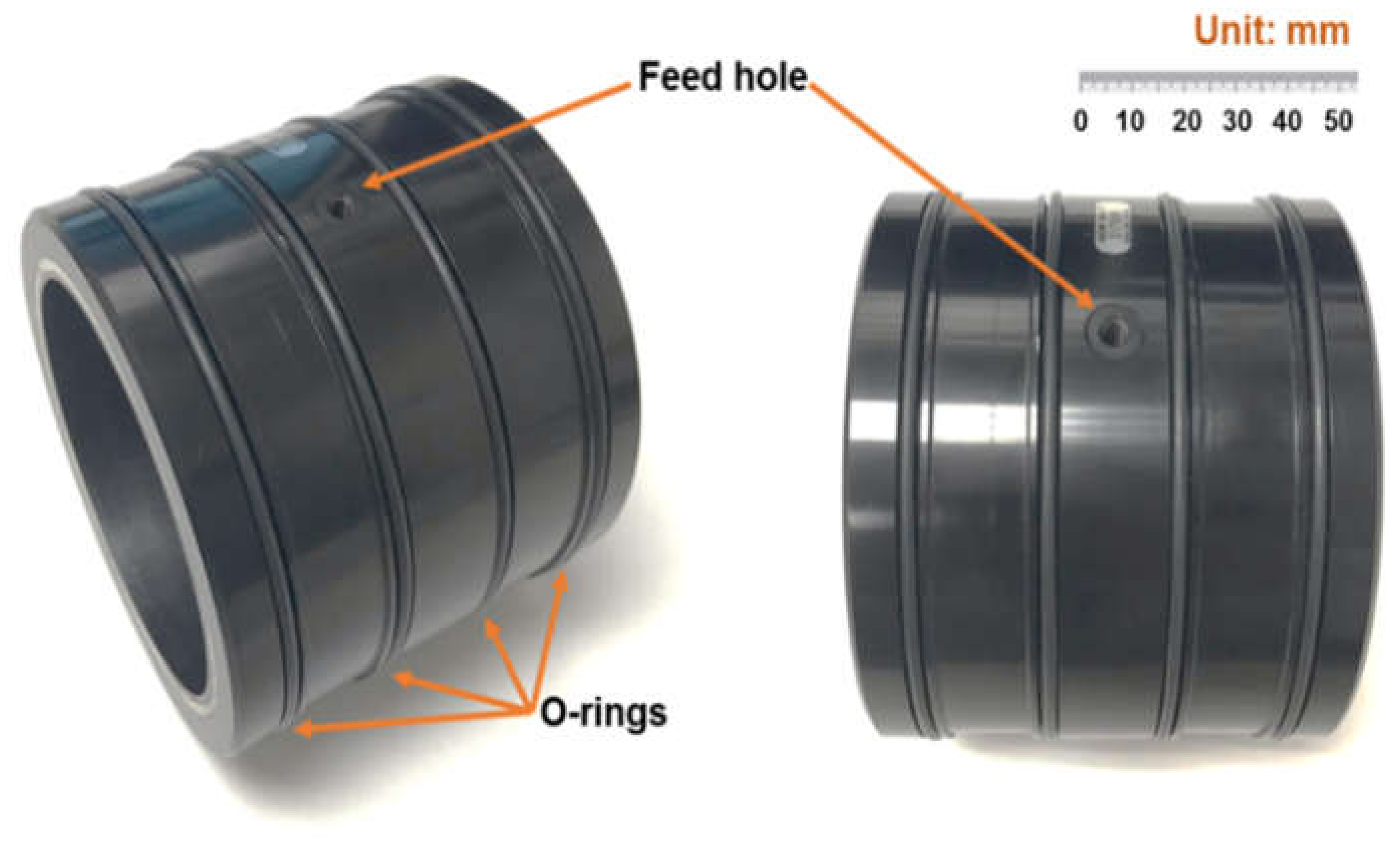
Figure 2 displays a photograph of a cylindrical PGB with physical dimensions listed in Table 1. The table also details the conditions for measurement of the supplied flow rate and estimation of κ. A product specification sheet is available in [27].
Without a shaft installed in the bearing, measurements of the air supply pressure (pS) and ensuing mass flow rate ( M ˙ max ) deliver an estimation of the permeability coefficient (κ) [20]. From Equation (11),
κ = M ˙ max c   π   D   L 2   t p   μ   R g T p S 2 p a 2 .
In the measurements, the supply pressure (pS) increases from 2.4 bar to 6.5 bar (absolute), and an accurate turbine type meter records the flow. Figure 3 shows M ˙ max vs. (pS2 − pa2), and the line fitting the data has a correlation factor R2 = 1.0. From the experimental data, κ = 8.2 × 10⁻¹⁶ m2, which is typical for the product.

7. PGB Mass Flow Rate, Peak Pressure, and Aerostatic Stiffness vs. Clearance

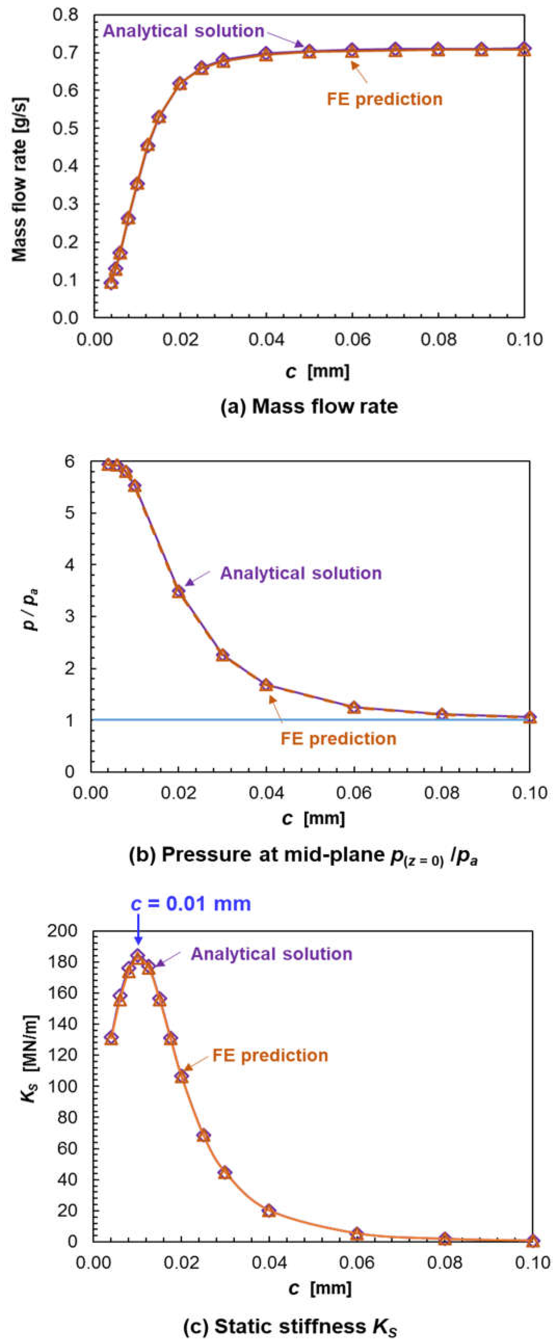
From Equation (9), the pressure at the bearing mid-plane (z = 0) is p z = 0 = p S 2 + p a 2 p S 2 cosh γ L D 1 . For the PGB with geometry listed in Table 1 and e = 0, Figure 4 depicts the mass flow rate ( M ˙ ), p z = 0 and the aerostatic stiffness KS (= KXXs = KYYs) vs. clearance for the PGB supplied with air at pS = 6 bar. Note the equivalent clearance for the porous layer cκ = (12 κ tp)1/3~3 μm.
The graphs include results from the exact solution and the FE computational model (1872 elements = 72 circumferential × 26 axial). Note that shaft speed has no effect on both parameters; see Reynolds Equation (7). The FE model flowrate is almost identical to the exact solution (difference less than 1%). For small clearances (c < 0.040 mm), M ˙ decreases quickly, p z = 0 pS, KS reaches a maximum (184 MN/m) at c = 0.010 mm, and then sharply decreases as c → 0. On the other hand, for c > 0.06 mm, M ˙ M ˙ max c = 0.73 g/s, p z = 0 pa, and KS → 0, i.e., a complete loss of load carrying capacity. Note c = 0.010 mm (D/c = 7610) ~ 3.3 cκ, though appearing to be tight (too small bearing clearances increase cost and make installation difficult), is quite appropriate for a gas bearing. Hence, the selection of the PGB clearance is most important to both keep a low flow rate while also providing enough load capacity and centering ability.
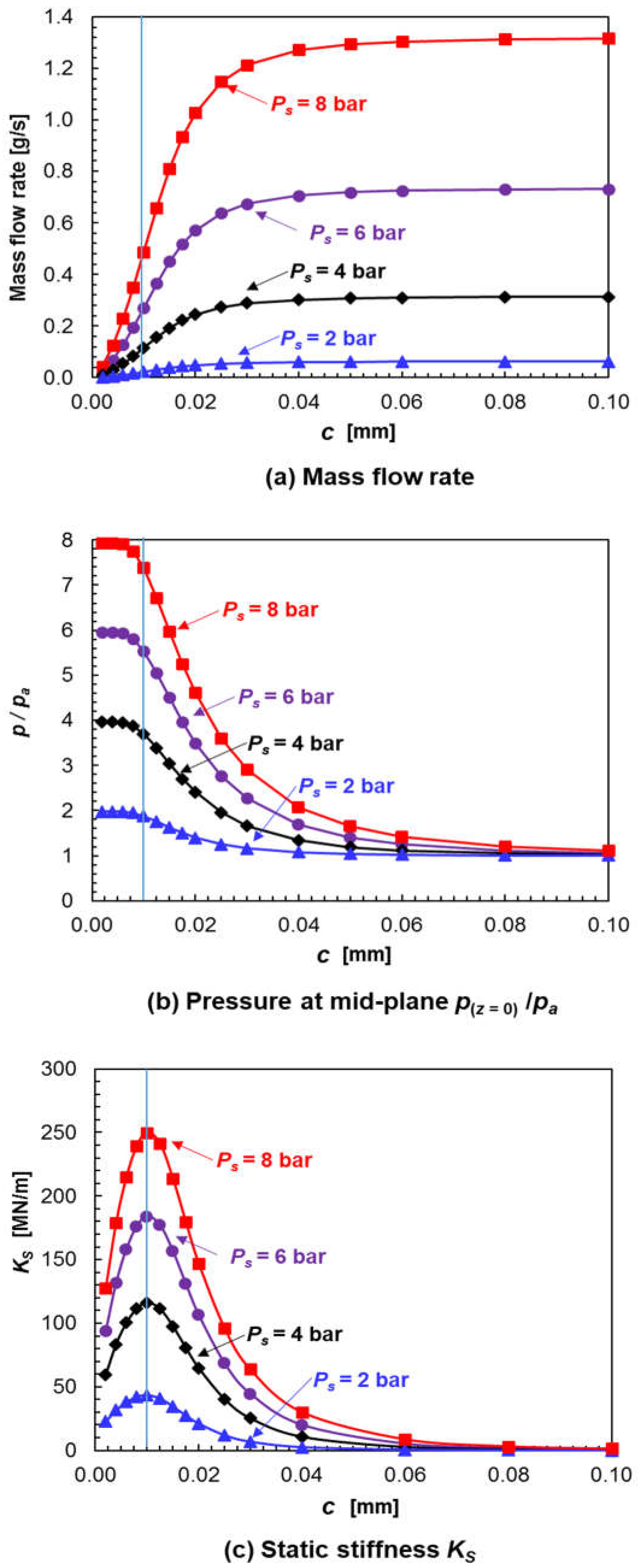
Having established the validity of the analytical solution versus a numerical solution, Figure 5 depicts p(z = 0)/pa, mass flow rate, and the (centering) aerostatic stiffness (KS) vs. clearance (c) for operation with supply pressure (pS) = 2, 4, 6, and 8 bar. The clearance ranges from a thin c = 0.002 mm (D/c = 38,105) to c = 0.1 mm (D/c = 762). Clearly, the film peak pressure, mass flow, and aerostatic stiffness increase with pS. As noted earlier, too large clearances (c > 0.040 mm → D/c < 1,900) produce no film pressure (ppa); hence, the PGB leaks too much (→ M ˙ max c   ) and is devoid of load capacity (KS → 0). For a very tight clearance (c < 0.005 mm), the mid-plane pressure pz=0pS, the flow ( M ˙ ) is small, and the direct stiffness is along a decreasing path. Independent of the supply pressure, the peak aerostatic stiffness appears at the same (narrow) clearance, c ~ 0.010 mm = 3.3 cκ. At this c, pz = 0/pa = 0.92 and M ˙ / M ˙ max = 0.37.
Although not shown for brevity, a dimensionless aerostatic stiffness scaled as K = K S   c / W * clusters the data in Figure 5c. At c = 0.010 mm, K ~ 0.6 for all pS. Being of order (1), the parametrization of K allows one to quickly estimate the (maximum) centering stiffness of any PGB having the same (κ/tp). The finding is nearly the same as that reported by Mori et al. [11,12] in 1968, K ~ 0.7.
The PGB product specification sheet [27] recommends a PGB with clearance c = 0.010 mm and, for operation with pressure supply pS = 5.15 bar [60 psig], quotes a static stiffness KS = 159 MN/m and flow of 13.2 L per minute (LPM) at standard conditions. For the same conditions, the current analysis predicts KS = 155.5 MN/m and a flow rate equaling to 9.86 LPM. The agreement in stiffness is remarkable, while the difference in flows indicates differing clearances. For example, for c = 0.012 mm (~20% larger), the analysis predicts 13.2 LPM flow and KS = 149 MN/m. Since the porous layer is affixed to the bearing housing using an adhesive, the manufacturer [27] specifies a maximum operating supply pressure of 7.9 bar (100 psig).

8. PGB Force Coefficients vs. Rotor Speed (Synchronous Frequency Condition)

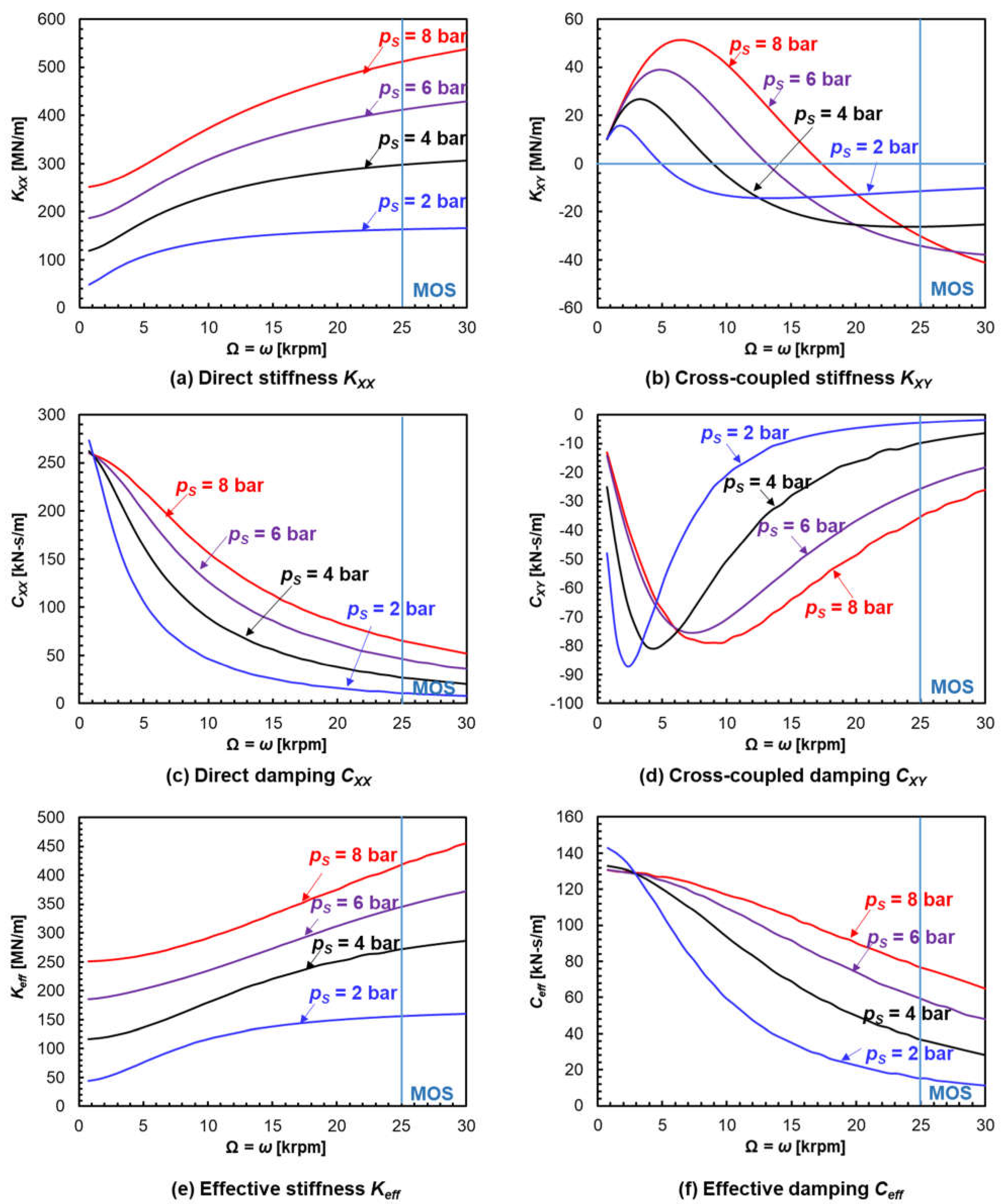
The analysis continues for the PGB with dimensions in Table 1 and for clearance c* = 0.010 mm, the one providing the peak aerostatic stiffness (KS). The operating speed range covers 0 to 30 krpm, with a mean operating speed (MOS) Ω* = 25 krpm (417 Hz); hence the shaft surface speed ΩR = 120 m/s. The pressure supply pS = 2 bar → 8 bar, and the ambient pressure pa = 1 bar. Note the feed flow parameter Λκ = γ2 = 5.3; and at the lowest supply pressure and MOS, Λ Ω * = 6 μ   Ω * p S R 2 c 2 ~21, thus indicating a moderate aerodynamic effect will assist with the generation of load capacity.
Figure 6 depicts the PGB force coefficients vs. shaft speed (Ω) and four pS. The coefficients are evaluated at a whirl frequency coinciding with shaft speed (ω = Ω), namely a synchronous speed condition. Note that at the centered condition, KXX = KYY, KXY = −KYX, CXX = CYY, and CXY = −CYX; see Equation (22). Effective force coefficients are
Keff = KXX + CXY ω, Ceff = CXX − KXY.
In general, the magnitude of the PGB force coefficients increases as the supply pressure grows. For hybrid operation (aerostatic plus aerodynamic effects), the direct stiffness (KXX) increases with rotor speed (Ω), whereas the direct damping CXX drops rapidly. At the top speed (30 krpm), KXX is approximately two times larger than at the low speed (aerostatic) condition. On the other hand, CXX reduces to ~1/5 in magnitude at low shaft speed. The cross-coupled stiffness KXY (<<KXX) is peculiar, as it reverses sign at a certain shaft speed. The larger pS is, the higher the speed at which KYX changes from positive to negative. Note −CXY << CXX with a peak magnitude at a certain shaft speed. Since CXY < 0, then Keff < KXX for all shaft speeds. At a low shaft speed condition, the effective damping is ~50% of CXX. On the other hand, at the high end of shaft speeds, Ceff is slightly larger than CXX since KXY < 0.

9. PGB Force Coefficients vs. Excitation Frequency

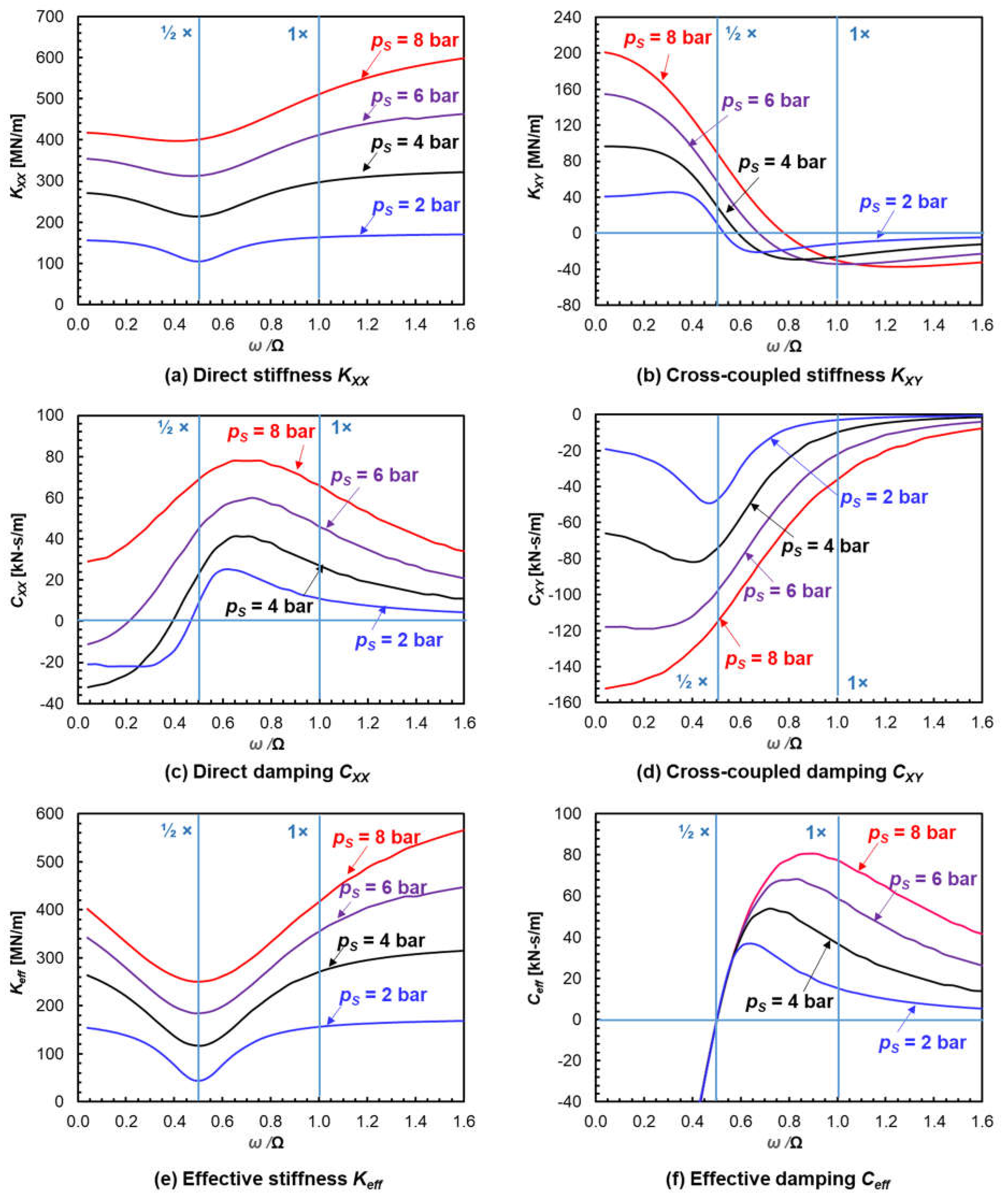
Figure 7 displays the PGB force coefficients vs. frequency ratio (ω/Ω*) for the bearing supplied with air at increasing pressures. In general, KXX grows (hardens) as the whirl frequency increases, whereas the direct damping (CXX) quickly drops. The magnitude of all force coefficients increases with an increase in gas supply pressure. In addition, at the cross-over frequency, ω = ½ Ω, half-frequency whirl, the effective stiffness (Keff) has a dip, and the effective damping turns positive, Ceff > 0. Hence, the PGB has the identical aerodynamic stability characteristics as a plain journal bearing. The predictions reveal that the cross-coupled stiffness (KXY) reverses sign for ω > ½ Ω, this frequency increasing as the supply pressure grows. Incidentally, for a low-pressure supply, pS < 4 bar, the direct damping is negative, CXX < 0, at low whirl frequencies (ω << Ω*). This effect is remarkable and a precursor to a pneumatic hammer; see [13].
In sum, shaft whirl motions at super synchronous motions (ω > ½ Ω), produce stiffness hardening and a marked reduction in effective damping. On the other hand, SSVs are likely to occur at ½ frequency whirl since Ceff = 0.

10. Stability of PGB

The stability of a point mass rotor (Mr) supported on one PGB is derived from   H ω   ω 2 M r   I   =   0   , where I is the 2 × 2 identity matrix. Following San Andrés [1], the instability threshold occurs at frequency ϖs defined when the equivalent complex stiffness He has its imaginary part Im (He) = 0 and its real part > zero. The equivalent complex stiffness (He) is defined as
H e ( ϖ ) =   1 2 H X X ϖ + H Y Y ϖ 1 4 H X X ϖ H Y Y ϖ 2 + H X Y ϖ H Y X ϖ   1 / 2 .
Recall that at the centered condition (e = 0), H X X = H Y Y , H X Y = H Y X . Hence, He becomes
H e ( ϖ ) =   H X X ϖ i   H X Y ϖ = K X X + ϖ C X Y ϖ + i ϖ C X X K X Y ϖ = K e f f ϖ + i   ϖ C e f f ( ϖ )
Im H e ϖ = 0     C e f f ϖ   = 0 ;   Re H e ϖ   > 0 M c r = K e f f ϖ ϖ 2 .
When ϖ = 1 2 Ω   C e f f ϖ = 0 , and taking the operating speed as being the threshold speed of instability (ΩT = Ω* = 2 ϖ ), then the largest mass the rotating system can hold is M c r = K e f f 1 2 Ω   T 1 2 Ω   T 2 . Table 2 lists the critical rotor mass for operation at various supply pressures and at MOS = 25 krpm. Mcr increases from 26.2 kg to 146.1 kg as pS = 2 bar → 8 bar. Note the weight of Mcr is much smaller than the PGB load capacity of ~(KΩ× c). Here K Ω = K X X 2 + K X Y 2 is a hybrid mode operation stiffness evaluated at the MOS (Ω*) and a zero whirl frequency (ω = 0).

11. PGB Load Capacity and Attitude Angle

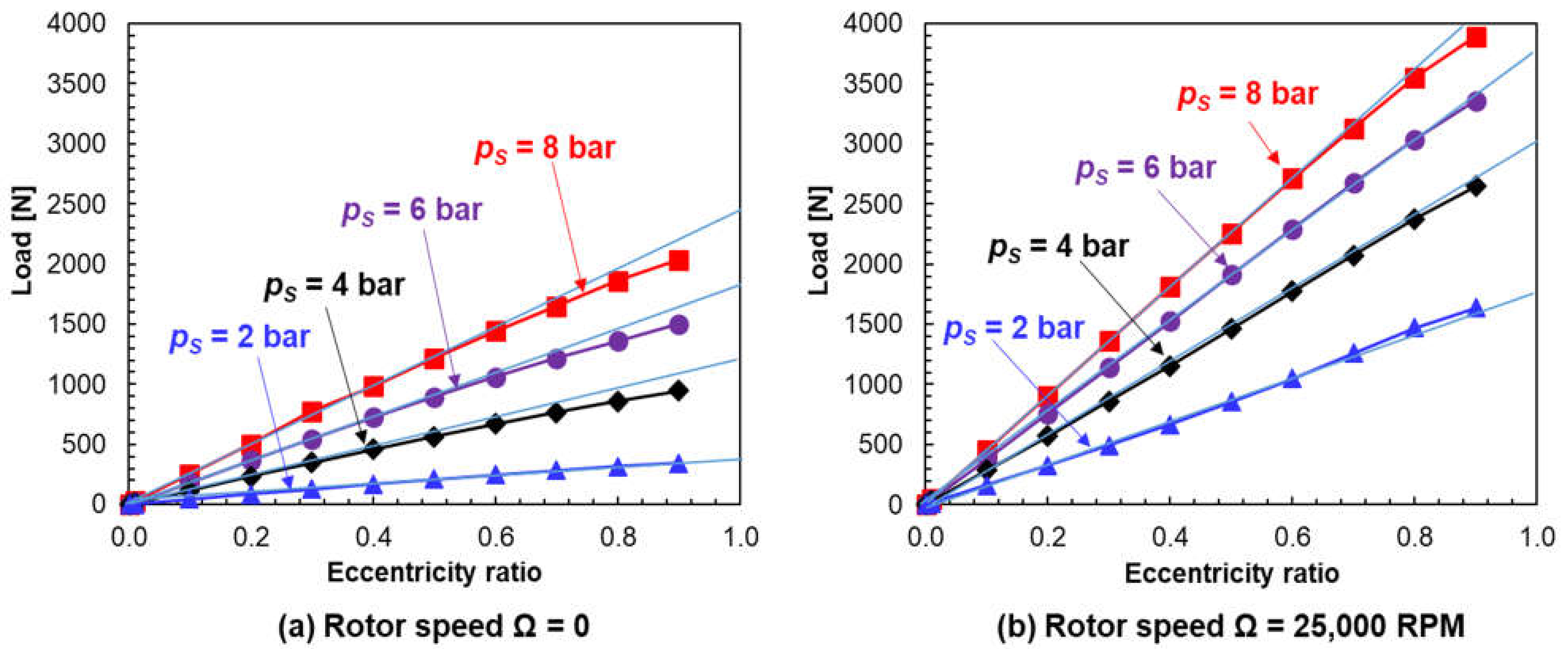
Predictions of the load carrying ability of the PGB for off-centered operation (e > 0) follow. Figure 8 depicts the load (W) vs. eccentricity ratio (e/c) for aerostatic operation (0 rpm) and at the mean MOS, Ω* = 25 krpm, and increasing magnitudes of air supply pressure. The results from the FE computational model (1872 elements = 72 circumferential × 26 axial), shown with dark symbols, reveal W increases with pS and is proportional to journal eccentricity (e). The graphs include light-colored lines that represent an approximate load derived from the product of the (exact) static stiffness at e = 0 times the journal eccentricity, i.e., Wapprox = (KS × e) when Ω = 0 (left graph), and Wapprox= (KΩ × e) at the MOS. Table 2 lists the magnitudes of the analytical force coefficients for the aerostatic (Ω = 0) and hybrid (Ω*) conditions.
Note the remarkable agreement between the analytical solution and the FE numerical solution for operation with journal eccentricity (e) as large as 70% of the bearing clearance. In short, the load capacity of the cylindrical PGB is proportional to the journal displacement (e). Furthermore, for the hybrid mode operating condition, the attitude angle (β) between the eccentricity vector and the applied load vector remains constant. As seen in Table 2, β increases from 14.6° to 25.7° as the supply pressure increases from two bar to eight bar.
The analysis and predictions demonstrate that the PGB is a linear mechanical element. Presently, based on the results shown in Figure 8, an estimation for the bearing load capacity equals W W * =   W p S p a L   D ~ 0.5 + 0.3 p a p S 1 + 0.13 Λ Ω .

12. An Example of Validation for the Static Performance of a PGB

Li et al. [23] detailed an investigation of the static and dynamic performance of an (in-house constructed) cylindrical PGB. As in the current paper, the authors of [23] built a computational finite difference (FD) model for prediction of performance of simple PGBs and to make pertinent distinctions for operation as purely aerostatic (Ω = 0), aerodynamic (pS = pa), and hybrid (Ω > 0, pS > pa). Authors in [6] also detailed a handful of experimental results for the measurement of applied load vs. journal eccentricity for a PGB with two distinct clearances, small (16 μm) and large (31 μm). Table 3 details the geometry, porous layer physical properties, and the operating conditions of the test PGB in [23]. Note that the reference has many clerical errors including dubious captions in several of the figure captions. In addition, the direct force coefficients presented in [23] follow trends not in accordance with the theory, the direct stiffness not agreeing with one derived from the static load (ω → 0). The work also gives a cursory review of the cross-coupled force coefficients.
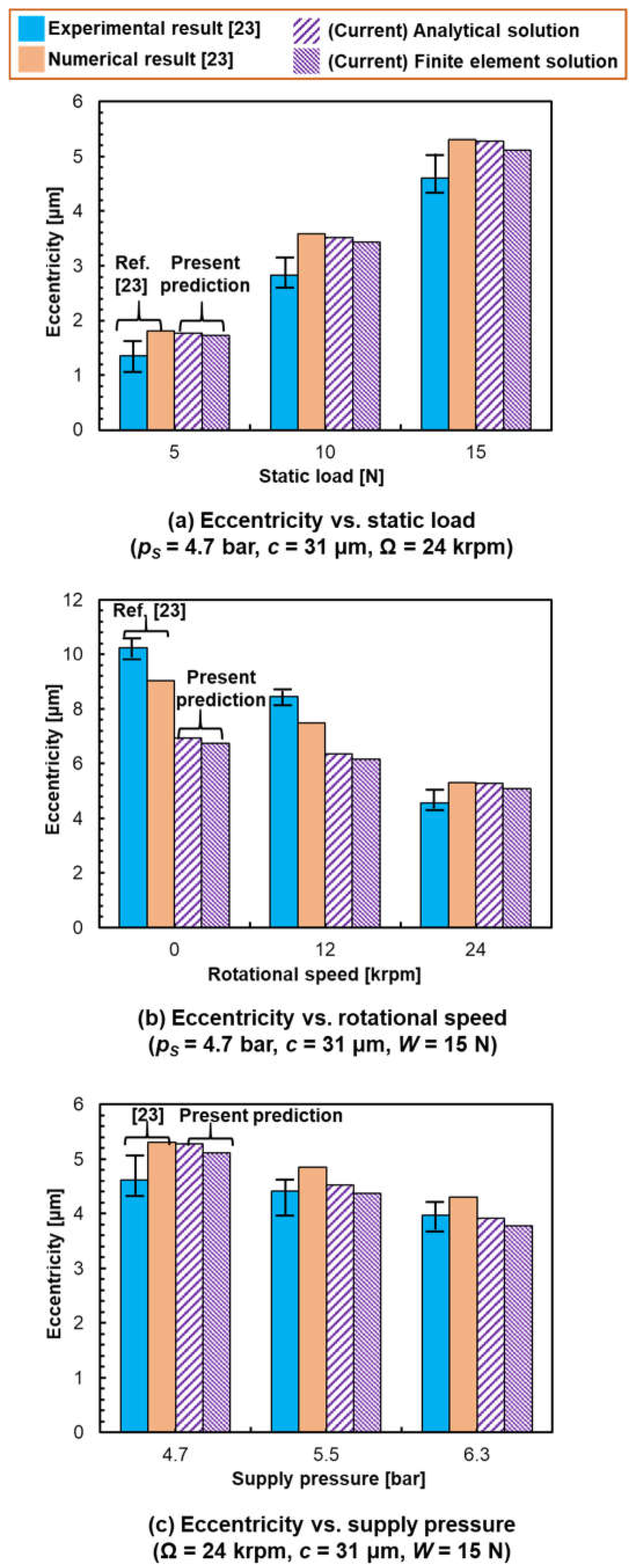
Figure 9 presents comparisons of the current analytical solution and FE model predictions vis-a-vis those in [23], experimental and numerical. As Figure 9a shows, the analytical solution and FE prediction of journal eccentricity (e) agrees well with the FD prediction [23] for pS = 4.7 bar, c = 31 μm and three static loads, 5 N to 15 N. For the top load of 15 N, the specific load W/(LD) = 0.1 bar; hence W/(LD)/(pS − pa) = 0.029, i.e., a very small load. The model predictions are slightly larger than the experimental results (ref. [23] does not report uncertainty or variability for the measured parameters nor variability for the force coefficients).
As per the journal eccentricity (e) vs. shaft speed and a fixed load (W = 15 N) (see Figure 9b), the current analytical and FE model predictions agree well with the experimental result at the top speed of 24 krpm. For pure aerostatic operation (Ω = 0), the current model predictions are ~32% smaller than the experimental result. Figure 9c displays eccentricity (e) vs. supply pressure (pS) for operation at 24 krpm (ΛΩ = 0.097 at pS = 4.7 bar). For pS = 5.5 and 6.3 bar, the current predictions match the experimental values, the difference <2%. For pS = 4.7 bar, the models produce a slightly larger (e) than the measured one.
Comparisons of predictions of the experimental force coefficients are omitted. As frequency grows, the test coefficients follow differing paths and have lower physical magnitudes than the model predictions, current and those in [23]. Feng [28] attributes the difference to the absence of a surface restrictive layer in the constructed PGB. Otsu et al. [18] explain difference in the performance of PGBs with and without the said restrictive layer. Interestingly enough, the current predictive model as well as that in [23] do not apply to PGBs with restrictive layers.

13. Conclusions

Porous surface gas bearings (PGBs) have come of age to enable high-speed, near friction free rotating machinery with improved reliability and availability. In the last decade (2012 and onward), numerous computational analyses for calculation of PGB forced performance, static and dynamic, have appeared. Most analyses, however, tackled the flow physical equations by computer while ignoring the vast body of archival literature on the subject.
The paper reviews the archival literature on PGBs and reproduces, using modest analytical means, an exact solution to the flow field and forced performance of a cylindrical PGB. This solution has been available since 1979 [5].
Predictions from the analysis serve to validate the results of a finite element computational model. Further comparisons to recent experimental results validate the analysis results and serve to elucidate the effect of external pressure and shaft speed on PGB performance. The learning from this work is as follows:
  • For a given external pressure, the supplied flow rate increases quickly as the bearing clearance enlarges and ultimately reaches a flow limit.
  • There is a narrow clearance region that ensures the maximum centering stiffness for a PGB. Selecting the appropriate clearance is necessary and rather difficult to achieve when also considering manufacturing costs and devising procedures for easy installation.
  • The load capacity of a PGB under aerostatic conditions is a fraction of the imposed pressure difference and the bearing projected area (L × D). The bearing load is proportional to the static eccentricity.
  • Under aerodynamic conditions, i.e., operation with shaft speed, the PGB load capacity still remains proportional to shaft eccentricity and can be much larger than the aerostatic load. That is, shaft speed shear flow effects increase the PGB load capacity.
  • For operation as the shaft speed varies from low (start-up) to the mean operating speed (MOS = Ω*) and above, the PGB bearing shows synchronous excitation (ω = Ω) force coefficients that increase in magnitude as pS increases. Most importantly, as the shaft speed increases, Keff increases (hardens) while Ceff decreases rapidly.
  • For operation at a constant (high) speed, the bearing effective stiffness (Keff) decreases at low whirl frequencies, reaches a dip or minimum at ½ whirl frequency operation (ω = ½ Ω), and then increases (hardens) as the frequency approaches synchronous speed (ω → Ω) and surpasses it. The bearing effective damping coefficient Ceff < 0 at low frequencies and equals zero at ω = ½ Ω. For larger ω, Ceff > 0 and reaches a peak at a certain frequency; the larger the external pressure pS, the higher the frequency at which Ceff is a maximum. For larger frequencies (ω >> Ω), Ceff → 0.
  • Note a PGB operating with shaft rotation (hybrid mode) has the same stability restriction as a plain cylindrical hydrodynamic bearing, i.e., a 50% whirl frequency ratio. However, a rigid rotor–PGB system natural frequency is rather large, since the bearing centering stiffness grows with both external pressurization and shaft speed. Hence, the threshold speed of instability, equal to two times the system natural frequency, can be tailored to exceed the system operating speed.
The authors hope other analysists, engineering students in particular, appreciate the effort to obtain the solution, the one that exactly predicts bearing performance and allows quick assessment of trends and selection of physical parameters. In a world ruled by complex numerical models attacking physics with computers, fundamental mathematics does bring meaning to an engineering endeavor as well as personal solace.

Author Contributions

Conceptualization, L.S.A. and A.D.; Formal analysis, L.S.A.; Funding acquisition, L.S.A.; Investigation, J.Y.; Project administration, L.S.A.; Resources, L.S.A. and A.D.; Software, J.Y.; Supervision, L.S.A.; Validation, J.Y.; Visualization, L.S.A. and J.Y.; Writing—original draft, L.S.A.; Writing—review & editing, L.S.A. and J.Y. All authors have read and agreed to the published version of the manuscript.

Funding

The research was funded by Texas A&M University-CONACYT Collaborative Research Program, and Texas A&M University J. Mike Walker ’66 Department of Mechanical Engineering 2020 Seed Grant.

Institutional Review Board Statement

Not applicable.

Informed Consent Statement

Not applicable.

Data Availability Statement

Not applicable.

Acknowledgments

Thanks to the Texas A&M University-CONACYT Collaborative Research Program, Texas A&M University J. Mike Walker ’66 Department of Mechanical Engineering 2020 Seed Grant, for partial financial support of the research. Thanks to NewWay® Air Bearings for donating the bearing.

Conflicts of Interest

The authors declare no conflict of interest.

Nomenclature

cBearing radial clearance (m)
cκ(12 κ tp)1/3. Equivalent clearance for layer of porous material (m)
CeffCeff = (CXXKXY/ω). Effective damping coefficient (N-s/m)
CXX, CYYDirect damping coefficients (N-s/m)
CXY, CYXCross-coupled damping coefficients (N-s/m)
D2R. Rotor diameter (m)
eJournal eccentricity (m)
(eX, eY)Components of journal eccentricity (m), e = e X 2 + e Y 2
(FX, FY)Bearing reaction force components along X and Y directions (N)
HeEquivalent complex stiffness at threshold speed of instability (N/m)
HXX, HYYDirect complex stiffness coefficients (N/m)
HXY, HYXCross coupled complex stiffness coefficients (N/m)
hFilm thickness (m)
KSPGB aerostatic (zero frequency) stiffness coefficient (N/m)
KeffKeff = KXX + CXY ·ω. Effective stiffness coefficient (N/m)
KΩ K X X 2 + K X Y 2 . PGB hybrid (zero frequency) stiffness coefficient (N/m)
KXX, KYYDirect stiffness coefficients (MN/m)
KXY, KYXCross-coupled stiffness coefficients (MN/m)
LBearing axial length (m)
MrMass of point rotor (kg)
McrMcr = Keff/ ϖ 2 . Rotor critical mass (kg)
M ˙ Mass flow rate through a porous gas bearing (kg/s)
M ˙ max Maximum mass flow rate for a porous gas bearing as c → ꝏ (kg/s)
pAbsolute pressure (bar)
pS, paSupply and ambient absolute pressures (bar)
RgGas constant (J/(kg K))
TSupply/ambient temperature (K)
ToDrag torque (Nm). Power loss = (To Ω)
tpPorous layer radial thickness (m)
WApplied load (N)
W*((pS − pa) L D). Nominal load for aerostatic operation
x = , zCoordinate system on bearing surface
X, YCartesian coordinate system
βAttitude angle (deg)
Λκ = γ2 3   κ t p c D c 2 . PGB feed flow parameter
ΛΩ 6 μ   Ω p S R c 2 . PGB speed number, Λ ¯ Ω = Λ Ω p S p ¯ 0
Λω 12 μ   ω p S R c 2 . PGB frequency number. Λ ¯ ω = Λ ω p S p ¯ 0
κPermeability coefficient for the porous material (m2)
μGas absolute viscosity (Pa-s)
ρp/(RgT). Gas density (kg/m3)
θCircumferential coordinate (-)
ωWhirl frequency (rad/s)
ϖ = ωn = ½ ΩT. Whirl frequency = natural frequency at threshold speed of instability (rad/s)
ΩRotor speed (rad/s)
ΩTThreshold speed of rotor stability (rad/s)
Abbreviations
FEFinite element
FDFinite difference
LPMLiter per minute
MOSMean operating speed
PGBPorous gas bearing
SSVSubsynchronous whirl vibration

References

  1. San Andrés, L. Modern Lubrication Theory, Notes 15: Gas Bearings for Oil-Free MTM; Texas A&M University Digital Libraries: College Station, TX, USA, 2020; Available online: http://oaktrust.library.tamu.edu/handle/1969.1/93197 (accessed on 27 June 2021).
  2. San Andrés, L.; Yang, J.; McGowan, R. Measurements of Static and Dynamic Load Performance of a 102 mm Carbon-Graphite Porous Surface Tilting-Pad Gas Journal Bearing. ASME J. Eng. Gas Turbines Power 2021. in print. [Google Scholar] [CrossRef]
  3. New Way Air Bearings. Air Bearing Application and Design Guide. Revision E. January 2006. Available online: https://www.newwayairbearings.com/sites/default/files/new_way_application_and_design_guide_%20Rev_E_2006-01-18.pdf (accessed on 27 June 2021).
  4. San Andrés, L.; Yang, J.; Devitt, A. About Tilting Pad Carbon-Graphite Porous Gas Bearings: Measurements in a Rotordynamic Test Rig and Predictions. Tribol. Trans. 2021. in print. [Google Scholar] [CrossRef]
  5. Gargiulo, E., Jr. Porous Wall Gas Lubricated Journal Bearings: Theoretical Investigation. ASME J. Lubr. Tech. 1979, 101, 458–465. [Google Scholar] [CrossRef]
  6. Sneck, H.; Yen, K. The Externally Pressurized, Porous Wall, Gas Lubricated Journal Bearing. ASLE Trans. 1964, 7, 288–298. [Google Scholar] [CrossRef]
  7. Sneck, H.; Elwell, R. The Externally Pressurized, Porous Wall, Gas Lubricated Journal Bearing. ASLE Trans. 1965, 8, 339–345. [Google Scholar] [CrossRef]
  8. Sneck, H.; Yen, K. The Externally Pressurized, Porous Wall, Gas Lubricated Journal Bearing. ASLE Trans. 1967, 10, 339–347. [Google Scholar] [CrossRef]
  9. Kwan, Y.P.B.; Corbett, J. Porous Aerostatic Bearings—An Updated Review. Wear 1998, 222, 69–73. [Google Scholar] [CrossRef]
  10. Belforte, G.; Raparelli, T.; Viktorov, V.; Trivella, A. Permeability and Inertial Coefficients of Porous Media for Air Bearing Feeding Systems. ASME J. Tribol. 2007, 129, 705–711. [Google Scholar] [CrossRef]
  11. Mori, H.; Yabe, H.; Yamakage, H.; Furukawa, J. Theoretical Analysis of Externally Pressurized Porous Journal Gas Bearings (1st Report). Bull JSME 1968, 11, 527–535. [Google Scholar] [CrossRef] [Green Version]
  12. Mori, H.; Yabe, H.; Yamakage, H. Theoretical Analysis of Externally Pressurized Porous Journal Gas Bearings (2nd Report, Journal Bearing with Solid Sleeves). Bull. JSME 1968, 11, 1512–1518. [Google Scholar] [CrossRef] [Green Version]
  13. Rao, N.S.; Majumdar, B.C. Dynamic Stiffness and Damping Coefficients of Aerostatic, Porous, Journal Gas Bearings. J. Mech. Eng. Sci. 1978, 20, 291–296. [Google Scholar] [CrossRef]
  14. Hwang, P. Pneumatic Hammer. Encyclopedia of Tribology; Springer: Berlin/Heidelberg, Germany, 2013; pp. 2545–2548. [Google Scholar]
  15. Lund, J.W. Calculation of Stiffness and Damping Properties of Gas Bearings. ASME J. Lubr. Tech. 1968, 90, 793–804. [Google Scholar] [CrossRef]
  16. Gargiulo, E., Jr. Porous Wall Gas Lubricated Journal Bearings: Experimental Investigation. ASME J. Lubr. Tech. 1979, 101, 466–473. [Google Scholar] [CrossRef]
  17. Miyatake, M.; Yoshimoto, S.; Sato, J. Whirling Instability of a Rotor Supported by Aerostatic Porous Journal Bearings with a Surface-Restricted Layer. Proc. Inst. Mech. Eng. Part J J. Eng. Tribol. 2006, 220, 95–103. [Google Scholar] [CrossRef]
  18. Otsu, Y.; Miyatake, M.; Yoshimoto, S. Dynamic Characteristics of Aerostatic Porous Journal Bearings with a Surface-Restricted Layer. ASME J. Tribol. 2011, 133, 011701. [Google Scholar] [CrossRef]
  19. San Andrés, L.; Jeung, S.-H.; Rohmer, M.; Devitt, D. Experimental Assessment of Drag and Rotordynamic Response for A Porous Type Gas Bearing. In Proceedings of the Extended Abstract, STLE Annual Meeting, Dallas, TX, USA, 17–21 May 2015; pp. 17–21. [Google Scholar]
  20. San Andrés, L.; Cable, A.T.; Zheng, Y.; De Santiago, O.; Devitt, D. Assessment of Porous Type Gas Bearings: Measurements of Bearing Performance and Rotor Vibrations. In Proceedings of the ASME Turbo Expo 2016: Turbine Technical Conference and Exposition, Seoul, Korea, 13–17 June 2016. ASME Paper GT2016-57876. [Google Scholar]
  21. Feng, K.; Wu, Y.; Liu, W.; Zhao, X.; Li, W. Theoretical Investigation on Porous Tilting Pad Bearings Considering Tilting Pad Motion and Porous Material Restriction. Precis. Eng. 2018, 53, 26–37. [Google Scholar] [CrossRef]
  22. Liu, W.; Feng, K.; Huo, Y.; Guo, Z. Measurements of the Rotordynamic Response of a Rotor Supported on Porous Type Gas Bearing. ASME J. Eng. Gas Turbines Power 2018, 140, 102501. [Google Scholar] [CrossRef]
  23. Li, W.; Wang, S.; Zhao, K.; Feng, K.; Hou, W. Numerical and Experimental Investigation on the Performance of Hybrid Porous Gas Journal Bearings. Lubr. Sci. 2020, 33, 60–68. [Google Scholar] [CrossRef]
  24. Bohle, M. Numerical Investigation of the Flow in Hydrostatic Journal Bearings with Porous Materials. In Proceedings of the ASME 2018 5th Joint US-European Fluids Engineering Division Summer Meeting, Montreal, QC, Canada, 15–20 July 2018. paper No. FEDSM 2018-83437. [Google Scholar]
  25. Lawrence, T.; Kemple, M. Numerical Method for Studying Bearing Gap Pressure Wave Development and Subsequent Performance Mapping of Externally Pressurized Gas Journal Bearings. In Proceedings of the ASME-JSME-KSME 8th Joint Fluids Engineering Conference, San Francisco, CA, USA, 28 July–1 August 2019. Paper No. AJKFluids 2019-4732. [Google Scholar]
  26. San Andrés, L. Hybrid Flexure Pivot-Tilting Pad Gas Bearings: Analysis and Experimental Validation. ASME J. Tribol. 2006, 128, 551–558. [Google Scholar] [CrossRef]
  27. NewWay® Air Bearings. Specification Sheet for Porous MediaTM Air Bushing, 3.00 Inch Inside Diameter. Part No. 3307501. Available online: https://www.newwayairbearings.com/catalog/product/air-bushings-english-3-00-inch-id/ (accessed on 27 June 2021).
  28. Feng, K. State Key Laboratory of Advanced Design and Manufacturing for Vehicle Body, Hunan University, Changsha, China. Personal communication, 2021. [Google Scholar]
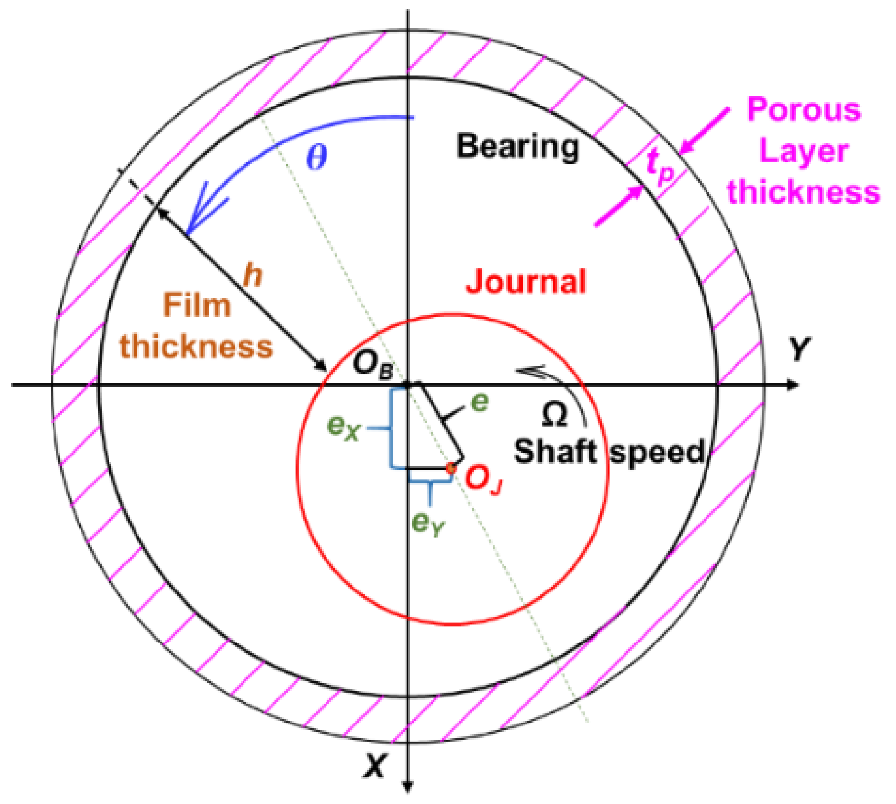
Figure 1. Schematic diagram of a cylindrical journal and bearing with porous material layer (not to scale). Coordinate system noted for reference.
Applsci 11 07949 g001
Figure 2. Photograph of a porous material cylindrical journal bearing.
Applsci 11 07949 g002
Figure 3. PGB measured mass flow rate M ˙ max vs. (pS2pa2) and a line fit (no shaft installed).
Applsci 11 07949 g003
Figure 4. PGB mass flow, pressure at bearing mid-plane, and aerostatic stiffness vs. clearance (c); (a) Mass flow rate; (b) Pressure at mid-plane p(z = 0)/pa; (c) Static stiffness KS. Analytical and FE predictions. Air supply pressure pS = 6 bar. Aerostatic operation at e = 0.
Applsci 11 07949 g004
Figure 5. PGB static pressure at mid-plane, mass flow rate, and aerostatic stiffness vs. clearance (c). Air supply pressure ps = 2, 4, 6, and 8 bar; (a) Mass flow rate; (b) Pressure at mid-plane p(z = 0)/pa; (c) Static stiffness KS. Aerostatic operation (Ω = 0) and null eccentricity (e = 0). Vertical lines denote clearance c = 0.01 mm for largest stiffness.
Applsci 11 07949 g005
Figure 6. PGB (synchronous frequency) force coefficients vs. shaft speed: (a,b) stiffnesses (KXX, KXY), (c,d) damping coefficients (CXX, CXY), (e,f) effective stiffness (Keff) and damping (Ceff) coefficients. Excitation frequency ω = Ω (synchronous with speed). Supply pressure pS = 2 to 8 bar; MOS = 25 krpm.
Applsci 11 07949 g006
Figure 7. PGB force coefficients vs. frequency ratio (ω/Ω). Mean operating speed Ω* = 25 krpm (417 Hz); (a,b) stiffnesses (KXX, KXY), (c,d) damping coefficients (CXX, CXY), (e,f) effective stiffness (Keff) and damping (Ceff) coefficients. Supply pressure pS = 2 to 8 bar.
Applsci 11 07949 g007
Figure 8. FE model of PGB load (W) vs. journal eccentricity ratio (e/c) at 0 rpm and 25 krpm shaft speed. Air supply pressure pS = 2, 4, 6, and 8 bar; (a) Load at 0 rpm; (b) Load at 25 krpm. PGB clearance c = 0.010 mm. (Light colored) straight lines represent approximate load capacity derived from the exact solution at e = 0.
Applsci 11 07949 g008
Figure 9. Predictions from current models (analytical and FE) compared to experimental results and predictions reported in [23]. (a) Journal eccentricity (e) vs. static load (W); (b) eccentricity (e) vs. shaft speed (Ω); (c) eccentricity (e) vs. supply pressure (pS).
Applsci 11 07949 g009
Table 1. Dimensions of porous journal bearing and operating conditions.
Bearing Length, L = 1.17 D88.8 mm (3.5 inch)
inner diameter, D76.2 mm (3.0 inch)
outer diameter, Dout99.5 mm (3.9 inch)
Carbon-graphite permeability, κ8.2 × 10⁻¹⁶ m2
Porous layer radial thickness, tp2.71 mm (0.11 inch)
Equivalent clearance for porous layer, cκ3 μm
Supply pressure, pS2–8 bar
Exit pressure, pa1 bar
Temperature, T294 K
Air density at (pa, T), ρa1.2 kg/m3
viscosity at (pS, T), μ18.3 × 10⁻⁶ Pa-s
gas constant, Rg287.05 J/(kg·K)
ParametersFor c = 0.010 mm
Feed flow parameterΛκ= 3   κ t p c D c 2 = 5.3
At pS = 6 bar, and Ω = ω = 22,618 rad/s (25 krpm)
Speed and frequency numbersΛΩ= 6 μ   Ω p S R c 2 = 7, Λω= 12 μ   ω p S R c 2 = 14
Table 2. Aerostatic and hybrid stiffnesses for PGB at the centered condition and rotor speed Ω = 0 and 25 krpm. Air supply pressure pS = 2, 4, 6, and 8 bar. Clearance c = 0.010 mm (Λκ = 5.3).
PressureAerostatic (Ω = 0)HybridΩ = 25 krpm Attitude Angle Critical Mass
pSKSKXXKXYKΩβKΩKSMcr
BarMN/mMN/mMN/mMN/mdegrees kg
2 bar431564116214.63.7626.2
4 bar1162719628819.62.4868.8
6 bar18435415538723.62.10107.7
8 bar25041820146425.71.85146.1
KXY = 0
Table 3. Operating conditions and dimensions of a cylindrical PGB reported in Ref. [23].
Bearing Length, L57 mm
Inner diameter, D25 mm (*)
Radial clearance, c16 μm, 31 μm
Porous layer radial thickness, tp2.5 mm
permeability coefficient, κ1.0 × 10⁻¹⁵ m2
Equivalent clearance porous layer, cκ3.1 μm
Supply pressure, pS4–6 bar (*)
Exit pressure, pa1 bar
Ambient temperature, T293 K
Air density at (pa, T), ρa1.2 kg/m3
viscosity at (pa, T), μ18.5 × 10⁻⁶ Pa-s
ParametersFor c = 0.031 mm, pS = 4.7 bar, and Ω = 2513 rad/s (24 krpm)
Feed flow parameterΛκ = 0.025
Speed numberΛΩ = 0.097
(*) Assumed since [23] has many clerical mistakes, as confirmed by one of the authors [28]. Ref. [23] also uses gauge pressure to report ps.
Publisher’s Note: MDPI stays neutral with regard to jurisdictional claims in published maps and institutional affiliations.