Article

Optimization of Neural Network-Based Self-Tuning PID Controllers for Second Order Mechanical Systems

1
Department of Mechanical Engineering, School of Industrial and Mechanical Engineering, The University of Suwon, 17, Wauan-gil, Bongdam-eup, Hwaseong 18323, Korea
2
Department of Mechanical Engineering, Myongji University, Yongin 17058, Korea
*
Author to whom correspondence should be addressed.
Appl. Sci. 2021, 11(17), 8002; https://doi.org/10.3390/app11178002
Submission received: 21 July 2021 / Revised: 22 August 2021 / Accepted: 26 August 2021 / Published: 29 August 2021
(This article belongs to the Section Mechanical Engineering)

Abstract

:
The feasibility of a neural network method was discussed in terms of a self-tuning proportional–integral–derivative (PID) controller. The proposed method was configured with two neural networks to dramatically reduce the number of tuning attempts with a practically achievable small amount of data acquisition. The first network identified the target system from response data, previous PID parameters, and response characteristics. The second network recommended PID parameters based on the results of the first network. The results showed that it could recommend PID parameters within 2 s of observing responses. When the number of trained data was as low as 1000, the performance efficiency of these methods was 92.9%, and the tuning was completed in an average of 2.94 attempts. Additionally, the robustness of these methods was determined by considering a system with noise or a situation when the target position was modified. These methods are also applicable for traditional PID controllers, thus enabling conservative industries to continue using PID controllers.

1. Introduction

The rapid development of process industries has resulted in an increase in the number of factories and machines, thus making it difficult for humans to monitor and operate all the machines during operation. Therefore, it is essential to develop technologies that automatically control the values of parameters such as pressure, velocity, temperature, and flow. The most widely used controller is the proportional–integral–derivative (PID) controller because it is effective despite its simplicity. It controls the output by calculating the error between the response and the target value [1,2,3]. In PID control, the response characteristics of the system vary according to the magnitude of the proportional, integral, and derivative terms, called PID parameters. When optimal values of PID parameters for the control object are set, the system shows a response close to the target value. However, if the system changes owing to deterioration or environmental changes, the PID parameters must also be changed dynamically to obtain a good response.
In general, to set an appropriate PID parameter, an expert familiar with the system adjusts the parameter using a trial-and-error method and simultaneously checks the response of the system to select the optimal value of the parameter. Experts commonly use methods such as the Ziegler–Nichols step response method, Chien–Hrones–Reswick method, ITAE, and robust PID tuning [4,5,6,7,8,9,10,11]. However, a major drawback of these methods is that the new PID parameters must be tuned manually whenever the characteristics of the system change; hence, complete automation of the tuning process is a challenge.
Despite the development of relevant software and hardware to tune the parameters, the process is time consuming [12,13,14,15,16]. Therefore, for complete automation, it is necessary to set the PID parameters quickly even without a human.
Methods have been developed for auto-tuning, such as a fuzzy logic controller. The fuzzy PID controller is a combination of classical PID control and fuzzy logic based on human knowledge and expertise [17]. It has been successfully applied in many nonlinear systems [18,19,20]. However, problems with fuzzy logic include the fact that the accuracy of responses depends on the knowledge and expertise of human beings, fuzzy rules must be updated with time, and there is no standard procedure for the design of the fuzzy controller. To compensate for the fuzzy PID controller, an adaptive neuro-fuzzy inference system (ANFIS) has been proposed. ANFIS is a combination of a neural network and a fuzzy logic controller [21,22,23]. ANFIS can successfully control a system by finding the values for fuzzy logic through a neural network without expert knowledge. Active disturbance rejection control (ADRC) is also a robust controller with the cancellation of disturbances [24,25,26]. However, ANFIS and ADRC cannot be applied to conservative industries that prefer the traditional PID controller with a PID parameter for safety because ANFIS control systems operate without PID parameters.
Artificial intelligence (AI) is the technology used to automate PID control. The research on PID control using AI has been conducted in two ways. First, to replace the PID controller with AI [27,28,29] and second, to automate the PID parameter setting [30,31,32,33,34]. The advantage of replacing the PID controller with AI is that the tuning of PID parameters is automated. However, certain industries still prefer the traditional approach to tune the PID controller, especially in conservative systems where safety is essential. Therefore, the automation of PID parameter settings is indispensable for complete system automation. Previous studies related to the automation of PID parameter settings using AI have drawbacks, such as only assisting tuning of the PID controller even after replacing with automated tuning with AI, or requiring multiple attempts to tune the parameters in spite of being learned because they are trained using reinforcement learning [30,31,32,33,34].
In this study, we developed a practical neural network method for conservative industries to automate the tuning of PID parameters that dramatically reduces the number of tuning attempts and can be learned with a practically achievable small amount of data. The proposed method was configured to identify the target system and then recommend PID parameters for the system. Additionally, it provided an understanding of the target system from the response characteristics and determined the PID parameters from the system in a minimal number of attempts. Moreover, it addressed the concerns of conservative industries that prefer using PID controllers. In addition, the number of sampling data required for AI learning was also examined, the stability of the response to noise was confirmed, and the variation in response when the target position was changed during the operation was studied.

2. Methods

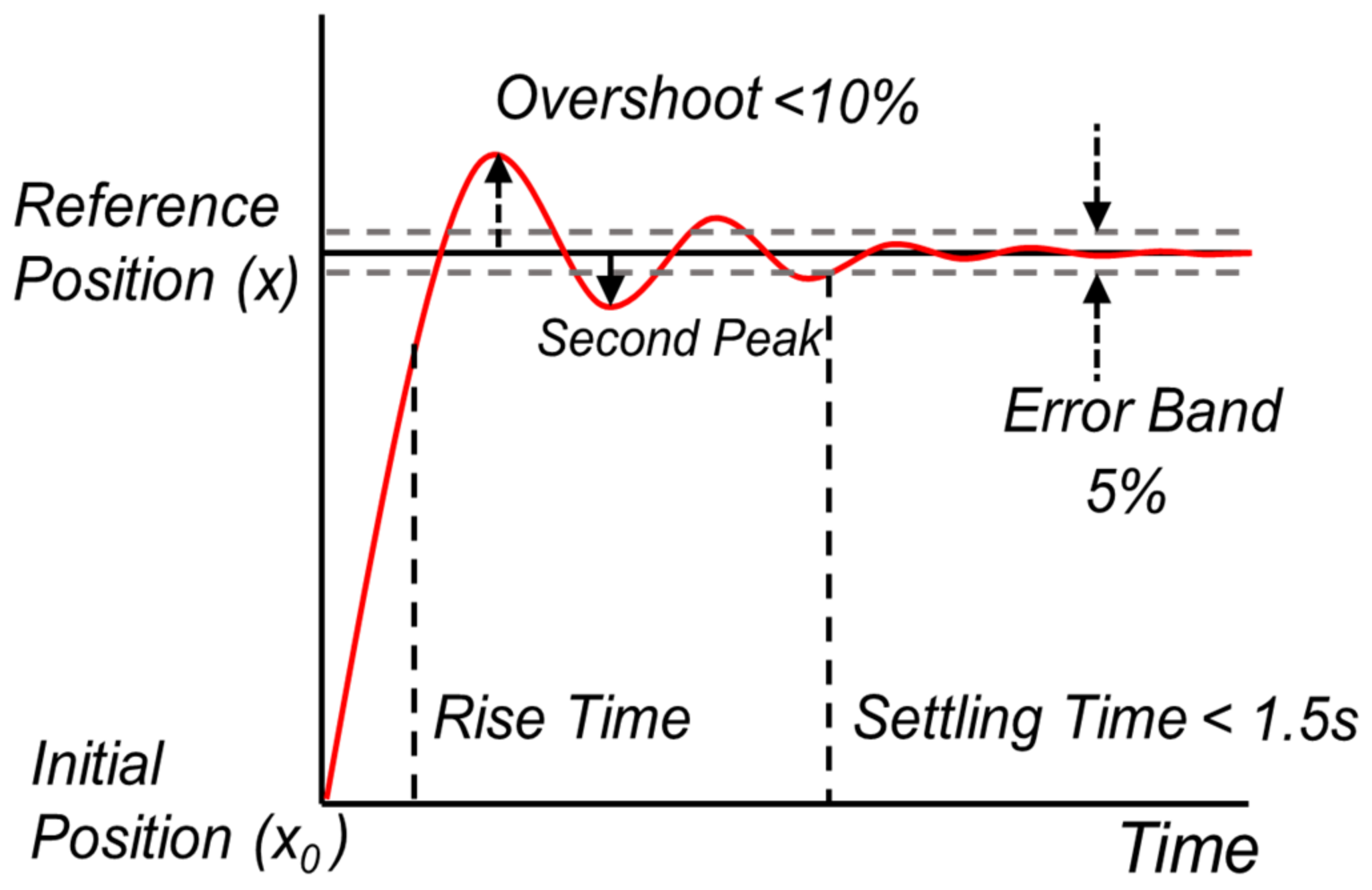
2.1. Simulator for PID Control

A simulator was designed to evaluate the output response and its characteristics for a given PID parameter and to check whether a proper response was produced when the AI method recommended the PID parameters. Additionally, it was also used to accumulate the response data according to the PID parameters for machine learning. The simulator was composed of a second-order system based on a simple mass–spring–damper model with the goal of position control. Most real-time systems can be approximated as second-order systems by model reduction [35,36,37,38,39]; hence, the mass–spring–damper model was selected (Figure 1).
The mass (m), spring (k), and damper (c) values were set as variables with SI units of kg, N/m, and N∙s/m, respectively. When the PID parameters were set, the position of the response along with its characteristics, such as overshoot, overshoot ratio, rise time, and settling time, were evaluated.
With a shorter settling time and smaller overshoot, better response characteristics, such as quick response and fast stability, were obtained. The acceptable response characteristics required for each system were different. For example, the level of water stored in a reservoir was controlled slowly, whereas the position of a robotic arm was controlled quickly. Hence, to obtain acceptable response characteristics in this study, the settling time and overshoot values were referenced from a similar research work [40,41,42,43]; the settling time with a 5% error band was less than 1.5 s and the overshoot was less than 10% (Figure 2).

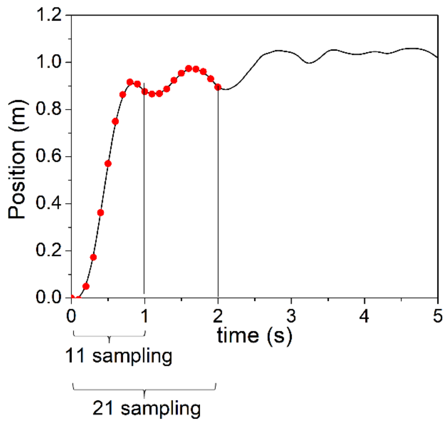
2.2. Data Acquisition for Learning and Testing

The data for PID learning were acquired as follows. In the simulator, the m, k, and c values along with the PID parameters were set to a random value between 0 and 1000. The initial position was at 0 m, the target position was fixed at 1 m, and the response was saved at 1000 Hz for 5 s. The neural network was trained to understand the system information by looking at the PID parameters, the response and its characteristics, and the values of m, k, and c. If the response of the system was not stable for 5 s, then the settling time was recorded as 5.001 s. A total of 10,000,000 sets of data were stored, and data creation took approximately 120 h with an Intel Xeon Gold 5220 CPU and an NVIDIA Titan RTX GPU.
In addition, the learning data recommended the optimal PID parameters from the identified system, and the acceptable PID parameters satisfying the specific criteria of settling time and overshoot, as mentioned in Section 2.1, were separately stored.

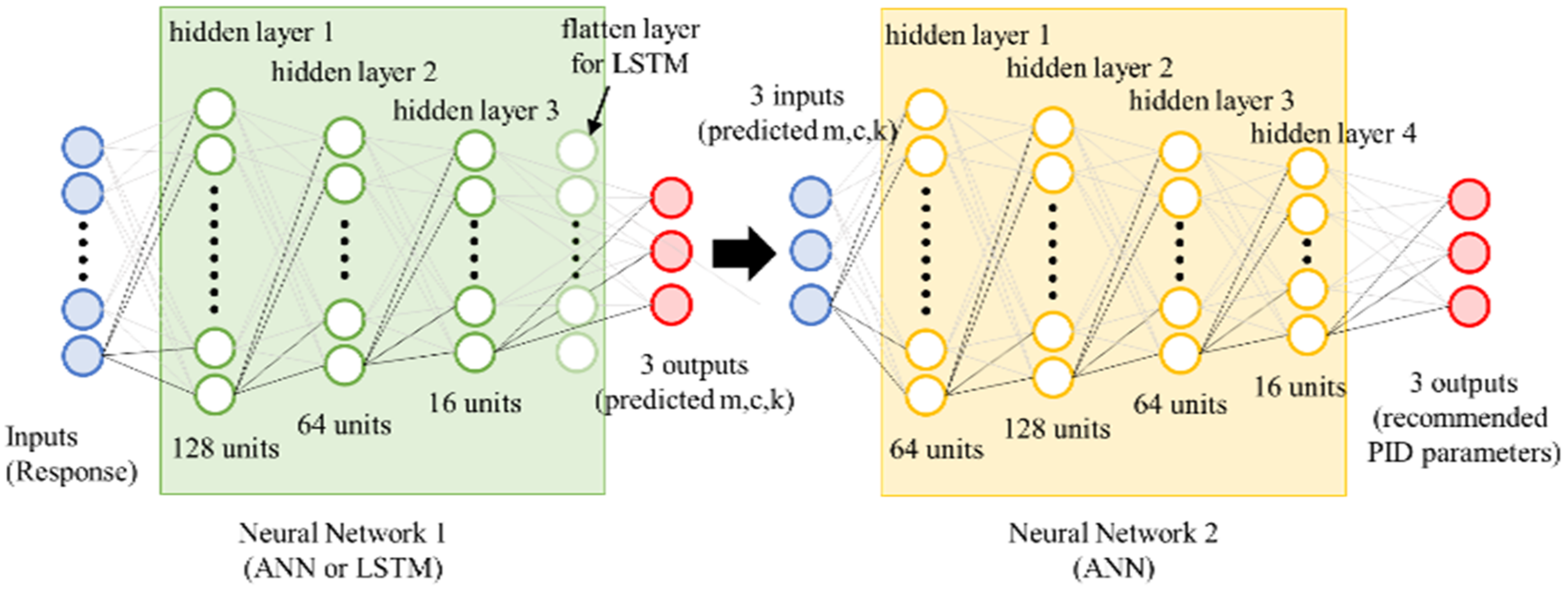
2.3. Learning Process

The originality of this study is the use of an AI method to recommend PID parameters after identifying the target system. In the proposed method, two neural networks were configured (Figure 3). One was configured to identify the type of system from the PID parameters and response characteristics, and the other to find the acceptable PID parameters for the identified system. These two neural networks were configured to work in series and recommend PID parameters quickly.
The first neural network was composed of two methods. One used a simple artificial neural network (ANN), and the other used a long short-term memory (LSTM) network that was capable of handling order dependence in sequential data. The ANN had three hidden layers and the LSTM had three hidden layers and one flattened layer. The ANN received inputs that included n sampling with position values at 0.1 s intervals (Figure 4), response characteristics, and PID parameters. In this method, response characteristics (RC) include values of: rise time when the position firstly reaches 95% of the target position; settling time, when the position settles with a 5% error band; overshoot, when the position reaches the highest position; and second peak, when the position reaches the second peak. LSTM received similar inputs as ANN that were converted to two-dimensional data to handle the sequential data. The outputs of both of the neural networks were m, k, and c.
The neural network inputs were given via eight approaches (Table 1). Two types of neural network were considered. The values of n were considered as 11 and 21, indicating that response data were sampled from 0 to 1 s and from 0 to 2 s at 0.1 s intervals for comparing the effect of the amount of sampling data considered as inputs. The response characteristics could be included or excluded for comparing the effect of response characteristics considered as an input.
The second neural network generated the output of the acceptable PID parameters from the values of m, k, and c. As it produced three outputs from three inputs, it was configured as a simple ANN with four hidden layers represented by groups of multiple neurons. This ANN was able to learn the acceptable PID parameters for the system.
For training, an Adam optimizer with a learning rate of 0.0005 and mean squared logarithmic error as loss was used. The activation functions used for the LSTM network and Multi-layer Perceptron (MLP) were tanh and ReLu, respectively. To prevent overfitting, a 10% of drop out method and L1, L2 regularizer method were used.
In this study, the data for learning were accumulated by simulation; hence, 10 million data samples could be produced at a time using this method. However, this was a challenge in real-time implementation. Therefore, in an actual PID system it is important to achieve an acceptable performance by generating the minimum amount of data. To check the amount of data required for learning, AI was trained by reducing the number of learning data in the order of 10 million, 10,000, and 1000.

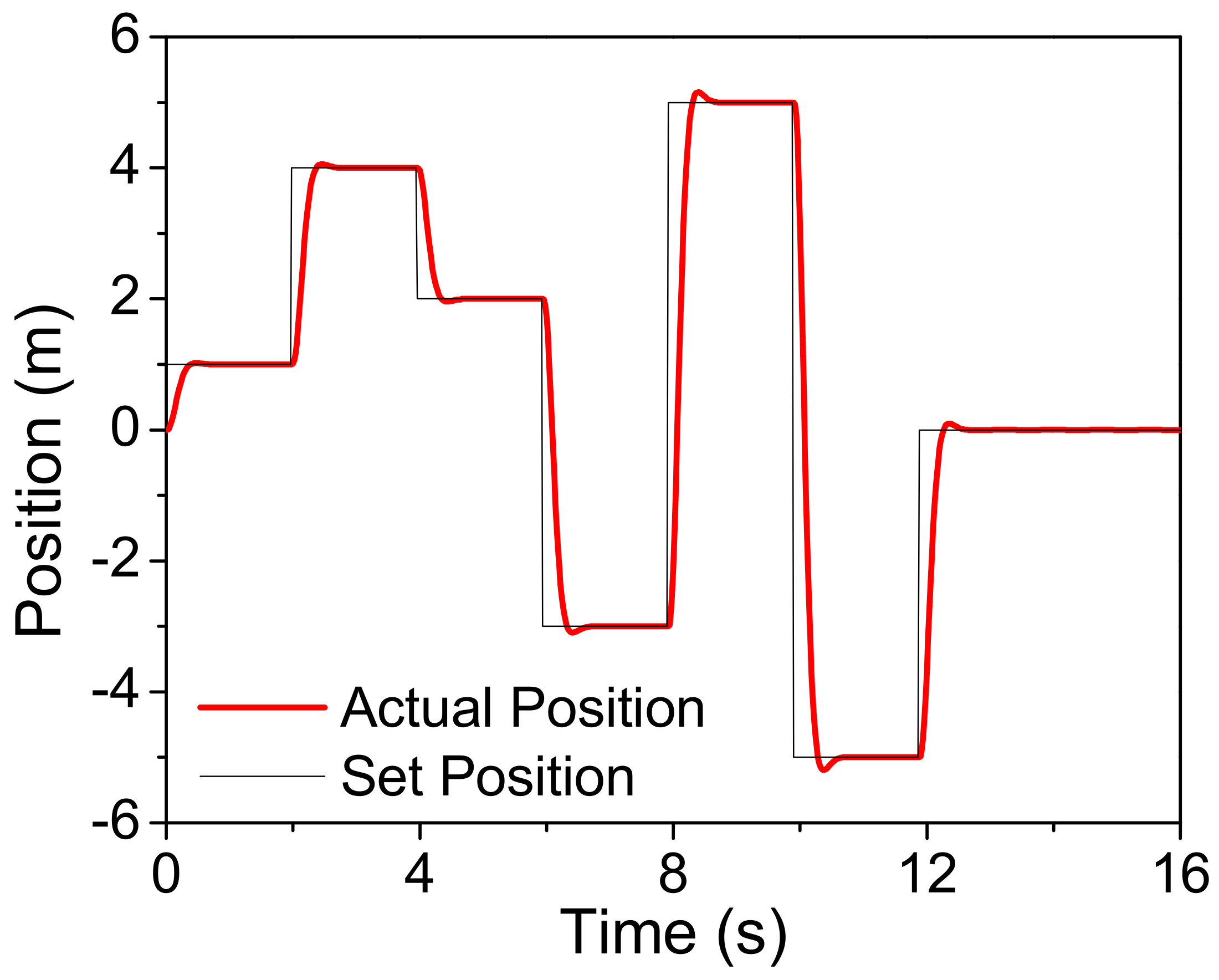
2.4. Inference and Performance Evaluation

The inference and performance evaluation of the system were performed using the random PID parameters considered initially. Then, the two neural networks recommended the new PID parameters from the response, response characteristics, and randomly input PID parameters. These recommended PID parameters were given as inputs to the simulator and the response, and its characteristics were checked again to confirm whether an acceptable tuning was achieved. The criteria of an acceptable response were when the settling time with a 5% error band was less than 1.5 s and the overshoot was less than 10%. If the response with the recommended PID parameters was not acceptable, the neural networks recommended new PID parameters based on the current response and the past values of the parameters. This was repeated until the tuning was complete. If tuning was not successful within 20 attempts, it was treated as a failure. To evaluate the performance of the system, the number of failures and trials to succeed were considered (Figure 5).
In addition, the performance of the system with noise was examined. Random noise, which has a normal distribution with a standard deviation of 20% of the settling condition, was added to the position every 0.01 s (Equation (1)). The performance of the system when the target position changed during the operation was also examined.
x t = x c o n t r o l l e d + N t
when x t : position at time t, x c o n t r o l l e d : position from PID controller, N t 1 2 π σ 2 e x μ 2 2 σ 2 0   w h e n   m o d t = 0.01   w h e n   m o d t 0.01 μ : mean of noise = 0, σ : standard deviation = 20% of settling condition = 0.2 ×   α , α : settling condition = 5% of target position.

3. Results

A total of 1000 cases of systems with random m, k, and c values were tested. Two neural network models were proposed to automate the tuning of PID parameters. The results indicated that the PID parameter tuning was completed in less than 1.6 attempts in every method, because these methods generated the acceptable PID parameters of the system as outputs after identifying the system from the response. An example of a response graph that changed as the tuning was repeated is shown in Figure 6.
According to the learning method classified by the type of network, number of sampling data, and whether response characteristics were included as inputs, the LSTM networks showed better performance in the results of both the first and second neural networks (Table 2 and Table 3). The relative error between real model parameters and predicted model parameters from the first neural network was between 14.5% and 37.6% (Table 2). The accuracy of the first neural network also affected the performance of the second neural network. When the relative error of the first neural network was low, the final results were also good. LSTM networks showed approximately 98% (~980 success per 1000 cases) success in tuning (Table 3). However, ANN with 21 and 11 sampling data without response characteristics showed poor performance. The performances of the LSTM network and ANN were similar when the input data included the response characteristics; however, there was a significant difference in the performances when the input data did not include the response characteristics. The performance of the LSTM network was 53% better than that of ANN when the input data did not include the response characteristics.
Based on the input features, both the methods with inputs including the number of sampling data and response characteristics showed approximately 98% success in tuning; however, when the input did not include response characteristics, the ANN showed unacceptable performance. Therefore, an LSTM network with an input sampling data size of 11 was recommended, because when the input was minimal, only 1 s of the response data was sufficient for tuning the PID parameter.
The advantages of using a neural network to identify the system are quick tuning of PID parameters and creation of learning data. Except for the reinforcement learning method, all other learning methods require optimal PID parameters to predict the subsequent parameters from the response. The methods using AI demonstrate high accuracy after learning multiple cases of predicting the optimal parameters and the response corresponding to each system with different m, k, and c values. Therefore, researchers must be able to identify multiple cases for predicting the optimal PID parameters for multiple cases of response of the random system to create learning data. However, there was no need to identify the optimal PID values for multiple cases of response from multiple cases of systems when one AI system identified the system from the response and another AI system identified the optimal PID parameters for the system. The values of m, k, and c corresponding to response and PID parameters were essential for learning with one AI system, and the optimal PID value data corresponding to the system were essential for learning with the other AI system. It was possible to learn efficiently even while generating data and with less data than AI, which directly connected the optimal PID value from the response. If the system is variable and the variation of the system is defined, the method of constructing two AIs is more effective in generating learning data.
However, the PID setting failed for certain values of m, k, and c, such as 0.1 kg, 900 N/m, and 900 Ns/m, respectively, because they could not be achieved in real systems; for example, feathers were placed on the spring and damper used in heavy equipment. In another failed case, the mass, spring, and damper were at the edge of the range of training data. As training data were generated randomly, the edge of the range may have been slightly learned or never learned. Therefore, the accuracy near the edge was reduced. This could be prevented by generating training data of a larger range.
The performance of LSTM networks with a reduction in the number of learning data in the order of 10 million, 10,000, and 1000 is shown in Table 4. The number of successful tuning attempts decreased with a decrease in the number of learned data. However, all the cases indicated a success rate of more than 93%. Additionally, the average number of successful tuning attempts increased with a decrease in the number of learned data. Even if only 1000 data were learned, the L-11 method showed 92.9% improvement in performance, and the tuning was completed in an average of 2.94 attempts. The 1000 samples of data could be generated in a real PID system.
When random noise with a standard deviation of 20% of settling condition was added to the data, the average number of tuning attempts to success and the number of failed tuning attempts tended to increase (Figure 7 and Table 5). The position of the system was sensitive to fluctuations in noise and a situation similar to the narrowing of settling condition was encountered. Hence, even if a successfully tuned PID parameter was used, random noise often resulted in a failure condition response. Therefore, it is suggested to evaluate the situation in which there is noise with more loose evaluation criteria such as changing the margin of the error band from 5% to 10%.
Additionally, the response of the system with the PID parameter recommended by neural networks was explored when the target position was changed during operation. In Figure 8, the responses of the system with m, k, and c as 70.3796 kg, 930.6824 N/m, and 313.7844 N∙s/m, and Kp, Ki, and Kd as 40.3243, 922.2207, and 122.4163 recommended by AI are plotted. The set position started at 0 m and changed to 1, 4, 2, −3, 5, −5, 0 m at 2 s intervals. Even if the set position was changed during the operation, the response of the system with PID parameters recommended by AI for the set position quickly followed the changed set position.

4. Conclusions

In this study, we proposed an AI method to automate the tuning of PID parameters. We designed a series of two AI systems to automate the tuning process and recommend acceptable PID parameters based on the response of the system. These models dramatically reduced the number of tuning attempts by identifying the target system and recommending PID parameters for the system.
Both ANN and LSTM networks showed satisfactory results; however, an LSTM network with 21 or 11 sampling data points without response characteristics was the most recommended because it could predict the next PID parameter based on the response data of 1 or 2 s. In addition, even for 1000 learned data, the L-11 method showed 92.9% improvement in performance and tuning was completed in an average of 2.94 attempts. The robustness of the proposed method was evaluated by determining the performance of the system with the addition of noise or when the target position was changed.
Additionally, this method can be used effectively even in conservative industries that prefer using traditional PID controllers. In the future, it will be necessary to use a more complex simulator such as a higher-order system to evaluate the performance of this method.

Author Contributions

Y.-S.L.; data acquisition, writing—original draft preparation, and editing, D.-W.J.; investigation, methodology, writing—original draft preparation, and editing. Both authors have read and agreed to the published version of the manuscript.

Funding

This work was supported by the National Research Foundation of Korea (NRF) grant funded by the Korean government (MSIT) (No. NRF-2020R1G1A1101591).

Institutional Review Board Statement

Not applicable.

Informed Consent Statement

Not applicable.

Data Availability Statement

Data sharing not applicable.

Conflicts of Interest

The authors declare no conflict of interest.

References

  1. Bennett, S. A Brief History of Automatic Control. IEEE Control Syst. Mag. 1996, 16, 17–25. [Google Scholar] [CrossRef]
  2. Bennett, S. Development of the PID Controller. IEEE Control Syst. Mag. 1993, 13, 58–62. [Google Scholar] [CrossRef]
  3. Ang, K.H.; Chong, G.; Li, Y. PID Control System Analysis, Design, and Technology. IEEE Trans. Control Syst. Technol. 2005, 13, 559–576. [Google Scholar] [CrossRef] [Green Version]
  4. Ziegler, J.G.; Nichols, N.B. Optimum Settings for Automatic Controllers. J. Dyn. Syst. Meas. Control Trans. ASME 1993, 115, 220–222. [Google Scholar] [CrossRef]
  5. Cohen, G.H.; Coon, G.A. Theoretical Consideration of Retarded Control. Trans. ASME 1953, 75, 827–834. [Google Scholar]
  6. Chien, K.L.; Hrons, J.A.; Reswick, J.B. On the Automatic Control of Generalized Passive Systems. Trans. Am. Soc. Mech. Eng. 1972, 74, 175–185. [Google Scholar]
  7. Åström, K.J.; Hägglund, T.; Hang, C.C.; Ho, W.K. Automatic Tuning and Adaptation for PID Controllers—A Survey. IFAC Proc. Vol. 1992, 25, 371–376. [Google Scholar] [CrossRef]
  8. Luyben, W.L. Tuning Proportional-Integral-Derivative Controllers for Integrator/Deadtime Processes. Ind. Eng. Chem. Res. 1996, 35, 3480–3483. [Google Scholar] [CrossRef]
  9. Maiti, D.; Acharya, A.; Chakraborty, M.; Konar, A.; Janarthanan, R. Tuning Pid and Piλdδ Controllers Using the Integral Time Absolute Error Criterion. In Proceedings of the 2008 4th International Conference on Information and Automation for Sustainability, Colombo, Sri Lanka, 12–14 December 2008; pp. 457–462. [Google Scholar]
  10. Foley, M.W.; Julien, R.H.; Copeland, B.R. A Comparison of PID Controller Tuning Methods. Can. J. Chem. Eng. 2005, 83, 712–722. [Google Scholar] [CrossRef]
  11. Portillo, J.; Marcos, M.; Orive, D.; López, F.; Pérez, F. PID_ATC: A Real-Time Tool for PID Control and Auto-Tuning. IFAC Proc. Vol. 1998, 31, 41–46. [Google Scholar] [CrossRef]
  12. Starr, K.D.; Petersen, H.; Bauer, M. Control Loop Performance Monitoring—ABB’s Experience over Two Decades. Proc. IFAC-PapersOnLine 2016, 49, 526–532. [Google Scholar] [CrossRef]
  13. Sutikno, J.P.; Chin, S.Y.; Abdul Aziz, B.B.; Mamat, R. Experimental Implementation of the Mp-GM (Maximum Peak—Gain Margin) Tuning Method: A Tuning Method for 2DOF-IMC under Uncertainty Process. In Proceedings of the 2012 International Conference on Systems and Informatics, Yantai, China, 19–20 May 2012; pp. 414–418. [Google Scholar]
  14. Sukede, A.K.; Arora, J. Auto Tuning of PID Controller. In Proceedings of the 2015 International Conference on Industrial Instrumentation and Control, Pune, India, 28–30 May 2015; Institute of Electrical and Electronics Engineers Inc.: New York, NY, USA, 6 July 2015; pp. 1459–1462. [Google Scholar]
  15. Versteeg, H.J.; Jansma, H.J.; Turner, K. Evaluation of Commercially Available Adaptive Controllers. Journal A 1986, 27, 120–126. [Google Scholar]
  16. Berner, J.; Soltesz, K.; Hägglund, T.; Åström, K.J. An Experimental Comparison of PID Autotuners. Control Eng. Pract. 2018, 73, 124–133. [Google Scholar] [CrossRef] [Green Version]
  17. Zadeh, L.A. Fuzzy Sets. Inf. Control 1965, 8, 338–353. [Google Scholar] [CrossRef] [Green Version]
  18. Gouda, M.M.; Danaher, S.; Underwood, C.P. Fuzzy Logic Control Versus Conventional PID Control for Controlling Indoor Temperature of a Building Space. IFAC Proc. Vol. 2000, 33, 249–254. [Google Scholar] [CrossRef]
  19. Tang, K.S.; Man, K.F.; Chen, G.; Kwong, S. An Optimal Fuzzy PID Controller. IEEE Trans. Ind. Electron. 2001, 48, 757–765. [Google Scholar] [CrossRef] [Green Version]
  20. Kim, J.H.; Oh, S.J. A Fuzzy PID Controller for Nonlinear and Uncertain Systems. Soft Comput. 2000, 4, 123–129. [Google Scholar] [CrossRef]
  21. Jang, J.S.R. ANFIS: Adaptive-Network-Based Fuzzy Inference System. IEEE Trans. Syst. Man Cybern. 1993, 23, 665–685. [Google Scholar] [CrossRef]
  22. Singh, M.; Chandra, A. Application of Adaptive Network-Based Fuzzy Inference System for Sensorless Control of PMSG-Based Wind Turbine with Nonlinear-Load-Compensation Capabilities. IEEE Trans. Power Electron. 2011, 26, 165–175. [Google Scholar] [CrossRef]
  23. Chang, F.J.; Chang, Y.T. Adaptive Neuro-Fuzzy Inference System for Prediction of Water Level in Reservoir. Adv. Water Resour. 2006, 29, 1–10. [Google Scholar] [CrossRef]
  24. Han, J. From PID to Active Disturbance Rejection Control. IEEE Trans. Ind. Electron. 2009, 56, 900–906. [Google Scholar] [CrossRef]
  25. Sun, L.; Xue, W.; Li, D.; Zhu, H.; Su, Z. gang Quantitative Tuning of Active Disturbance Rejection Controller for FOPDT Model with Application to Power Plant Control. IEEE Trans. Ind. Electron. 2021. [Google Scholar] [CrossRef]
  26. Sun, L.; Li, D.; Hu, K.; Lee, K.Y.; Pan, F. On Tuning and Practical Implementation of Active Disturbance Rejection Controller: A Case Study from a Regenerative Heater in a 1000 MW Power Plant. Ind. Eng. Chem. Res. 2016, 55, 6686–6695. [Google Scholar] [CrossRef]
  27. Ahmed, A.A.; Saleh Alshandoli, A.F. On Replacing a PID Controller with Neural Network Controller for Segway. In Proceedings of the 2020 International Conference on Electrical Engineering, Yogyakarta, Indonesia, 1–2 October 2020; Institute of Electrical and Electronics Engineers Inc.: New York, NY, USA, 25 September 2020. [Google Scholar]
  28. Cheon, K.; Kim, J.; Hamadache, M.; Lee, D. On Replacing PID Controller with Deep Learning Controller for DC Motor System. J. Autom. Control Eng. 2015, 3, 452–456. [Google Scholar] [CrossRef]
  29. Salloom, T.; Yu, X.; He, W.; Kaynak, O. Adaptive Neural Network Control of Underwater Robotic Manipulators Tuned by a Genetic Algorithm. J. Intell. Robot. Syst. Theory Appl. 2020, 97, 657–672. [Google Scholar] [CrossRef]
  30. Jung, S.; Kim, S.S. Control Experiment of a Wheel-Driven Mobile Inverted Pendulum Using Neural Network. IEEE Trans. Control Syst. Technol. 2008, 16, 297–303. [Google Scholar] [CrossRef]
  31. Wang, X.-S.; Cheng, Y.-H.; Sun, W. A Proposal of Adaptive PID Controller Based on Reinforcement Learning. J. China Univ. Min. Technol. 2007, 17, 40–44. [Google Scholar] [CrossRef]
  32. Shipman, W.J.; Coetzee, L.C. Reinforcement Learning and Deep Neural Networks for PI Controller Tuning. Proc. IFAC-PapersOnLine 2019, 52, 111–116. [Google Scholar] [CrossRef]
  33. Arzaghi-Haris, D. Adaptive PID Controller Based on Reinforcement Learning for Wind Turbine Control. In Proceedings of the 6th WSEAS International Conference on Environment, Ecosystems and Development, Timisoara, Romania, 21–23 October 2010; p. 7. [Google Scholar]
  34. Sun, Q.; Du, C.; Duan, Y.; Ren, H.; Li, H. Design and Application of Adaptive PID Controller Based on Asynchronous Advantage Actor–Critic Learning Method. Wirel. Netw. 2019, 1–11. [Google Scholar] [CrossRef] [Green Version]
  35. Isaksson, A.J.; Graebe, S.F. Model Reduction for PID Design. IFAC Proc. Vol. 1993, 26, 467–472. [Google Scholar] [CrossRef]
  36. Davison, E.J. A Method for Simplifying Linear Dynamic Systems. IEEE Trans. Autom. Control 1966, 11, 93–101. [Google Scholar] [CrossRef]
  37. Shamash, Y. Model Reduction Using the Routh Stability Criterion and the Pade Approximation Technique. Int. J. Control 1975, 21, 475–484. [Google Scholar] [CrossRef]
  38. Skogestad, S. Simple Analytic Rules for Model Reduction and PID Controller Tuning. J. Process Control 2003, 13, 291–309. [Google Scholar] [CrossRef] [Green Version]
  39. Deniz, F.N.; Alagoz, B.B.; Tan, N. PID Controller Design Based on Second Order Model Approximation by Using Stability Boundary Locus Fitting. In Proceedings of the ELECO 2015—9th International Conference on Electrical and Electronics Engineering, Bursa, Turkey, 26–28 November 2015; Institute of Electrical and Electronics Engineers Inc.: New York, NY, USA, 28 January 2016; pp. 827–831. [Google Scholar]
  40. Sahib, M.A.; Ahmed, B.S. A New Multiobjective Performance Criterion Used in PID Tuning Optimization Algorithms. J. Adv. Res. 2016, 7, 125–134. [Google Scholar] [CrossRef] [Green Version]
  41. Micev, M.; Ćalasan, M.; Ali, Z.M.; Hasanien, H.M.; Abdel Aleem, S.H.E. Optimal Design of Automatic Voltage Regulation Controller Using Hybrid Simulated Annealing—Manta Ray Foraging Optimization Algorithm. Ain. Shams Eng. J. 2021, 12, 641–657. [Google Scholar] [CrossRef]
  42. Kurokawa, R.; Sato, T.; Vilanova, R.; Konishi, Y. Design of Optimal PID Control with a Sensitivity Function for Resonance Phenomenon-Involved Second-Order Plus Dead-Time System. J. Frankl. Inst. 2020, 357, 4187–4211. [Google Scholar] [CrossRef]
  43. Xue, D.; Chen, Y.; Atherton, D.P. Linear Feedback Control: Analysis and Design with MATLAB; Society for Industrial and Applied Mathematics: Philadelphia, PA, USA, 2007. [Google Scholar]
Figure 1. Mass–spring–damper system for simulation. Symbols m, k, and c indicate the values of the mass, spring, and damper, respectively.
Applsci 11 08002 g001
Figure 2. Ideal criteria for acceptable response characteristics.
Applsci 11 08002 g002
Figure 3. Architectures of the two proposed neural networks.
Applsci 11 08002 g003
Figure 4. Sampling method for using the data as inputs when number of sampling was 11 or 21.
Applsci 11 08002 g004
Figure 5. Flowchart of the tuning process using neural networks.
Applsci 11 08002 g005
Figure 6. Response graphs with the changes as tuning was repeated when m = 187.77 kg, k = 318.47 N/m, and c = 88.65 N∙s/m.
Applsci 11 08002 g006
Figure 7. Response graphs of L-11-1000 with noise that changed as tuning was repeated for m = 38.08 kg, k = 80.73 N/m, and c = 807.74 N∙s/m.
Applsci 11 08002 g007
Figure 8. Position tracking of the performance of the system with PID parameters recommended by the neural networks.
Applsci 11 08002 g008
Table 1. Learning method classified by the type of network, number of sampling data, and whether response characteristics were included as inputs. ANN and LSTM are abbreviated as “A” and “L”, respectively. The numbers “21” and “11” indicate the number of sampling data. “RC” indicates if the input included or excluded the response characteristics. If the name of the method does not end with “RC,” then the input of that method did not include response characteristics.
MethodType of NetworkNumber of Sampling Data (N)Response Characteristic (RC)
A-21-RCANN21Included
A-11-RCANN11Included
A-21ANN21Excluded
A-11ANN11Excluded
L-21-RCLSTM21Included
L-11-RCLSTM11Included
L-21LSTM21Excluded
L-11LSTM11Excluded
Table 2. The relative error between real model parameter and predicted model parameter from the first neural network for model identification after training 10 million data.
MethodRelative Error (%)
MassSpringDamperAverage
A-21-RC4.379.9029.314.5
A-11-RC4.0712.236.817.6
A-2132.530.026.629.7
A-1134.352.326.137.6
L-21-RC5.8113.426.515.2
L-11-RC6.5025.015.315.6
L-2115.317.917.616.9
L-1110.025.734.623.3
Table 3. Number of successful cases and average number of tuning attempts to achieve success using eight methods after training 10 million data.
MethodNumber of Successful Cases
(Total 1000 Cases)
Average Number of Tuning Attempts to Achieve Success
A-21-RC9851.047
A-11-RC9911.115
A-217381.344
A-115521.001
L-21-RC9821.085
L-11-RC9791.048
L-219921.004
L-119921.571
Table 4. Number of successful tuning attempts and average number of tuning attempts to success using LSTM networks by reducing the number of learning data. “# of Succ.” means number of successful attempts, and “# of Tune.” means average number of tuning attempts to success.
MethodNumber of Trained Data
10 Million10,0001000
# of Succ.# of Tune.# of Succ.# of Tune.# of Succ.# of Tune
L-21-RC9821.1859831.2659632.478
L-11-RC9791.0489131.6859642.621
L-119921.5719821.8649292.940
Table 5. Number of successful tuning attempts and average number of tuning attempts to success using LSTM networks by reducing the number of learning data. The number “1000” in the method L-21-RC-1000 and L-11-1000 means that these methods trained only 1000 of the total data.
Method with NoiseNumber of Successful Tuning Attempts (Total 1000)Average Number of Tuning Attempts to Success
L-21-RC9742.82546
L-21-RC-10009343.15096
L-119961.85241
L-11-10009443.29131
Publisher’s Note: MDPI stays neutral with regard to jurisdictional claims in published maps and institutional affiliations.

