Article

An Engineering Design Approach for the Development of an Autonomous Sailboat to Cross the Atlantic Ocean

by
Tanaka Akiyama
1,†,
Jean-Francois Bousquet
1,*,†,
Kostia Roncin
2,†,
Graham Muirhead
1,† and
Alexandra Whidden
1,†
1
Faculty of Engineering, Dalhousie University, Halifax, NS B3H 4R2, Canada
2
Centre of Research of École de l’Air UR 09.401, French Air Force Academy, CREA, BA 701, F-13661 Salon de Provence, France
*
Author to whom correspondence should be addressed.
These authors contributed equally to this work.
Appl. Sci. 2021, 11(17), 8046; https://doi.org/10.3390/app11178046
Submission received: 22 July 2021 / Revised: 11 August 2021 / Accepted: 24 August 2021 / Published: 30 August 2021
(This article belongs to the Special Issue Robotic Sailing and Support Technologies)

Abstract

:
Over the past decade, interest in autonomous vessels significantly increased as the technology improved, especially in the automotive industry. Unlike cars, ships travel in a wild environment and maritime lanes are not limited by white lines. This makes the design of fully autonomous vessels even more challenging. Additionally, the need to reduce greenhouse gas emissions led to a renewed interest in wind propulsion. Sailboats have several advantages, such as full energy autonomy and a limited environmental impact. The Microtransat Challenge, which consists of crossing the Atlantic Ocean, is a tremendous test field. This paper describes, within that frame, a design procedure for the development of a robust fully autonomous sailboat to be deployed for long-term missions. In this paper, the mechanical and electronic design strategies are presented. A focus is on reliability and power management. Moreover, a test procedure for validating each design increment is described as well as a path plan that considers the risk of collision and weather routing with wind and currents. The Microtransat remains a challenge that no autonomous ship has ever succeeded (and has been completed by a single unmanned vessel, SB Met in 2018). However, the results by Breizh Tigresse and Sealeon in 2015 and 2018 made a step forward in terms of time and distance. They are presented and analyzed in this work.

Graphical Abstract

1. Introduction

The development of drones has allowed the non-invasive monitoring and exploration of remote areas on Earth. To monitor the oceans using unmanned vehicles, autonomous underwater vessels (AUVs) can be deployed below the sea surface, and while their ability to navigate at different depths allows them to be covert, their construction is expensive to sustain the water pressure. As an alternative, unmanned surface vehicles (USVs) such as the wave glider can monitor the ocean at the air–water interface [1,2]. In the past few years, autonomous sailboats have gained interest as a USV, since they provide a low-cost, sustainable solution to monitor the oceans using a silent propulsion system. In fact, the sailboat is particularly attractive to monitor marine mammals [3,4] because it is nonthreatening to animals.
There have been a number of initiatives to design and optimize the sailboat for various missions. Saildrone commercialized a 7 m long vessel with a rigid sail. Its average speed is on the order of 2 knots [4,5]. Moreover, a number of competitions were initiated in the past 10 to 15 years. Originally, missions were short, and early competitions were held on lakes. In 2005, the Microtransat Challenge was launched with the ambitious goal to cross the Atlantic Ocean using robotic sailboats with a maximum length of 2.4 m to prevent damage to other vessels. Two classes exist: fully autonomous designs, in which communication to the sailboat is not allowed, and the unmanned division that allows data to be sent to the boat. Since then, 27 autonomous sailboats have attempted the challenge; however, none have successfully completed it. A single boat, the SB Met, completed it in the unmanned division.
In 2015, the Faculty of Engineering at Dalhousie University participated in the Microtransat for the first time, in collaboration with Ensta-Bretagne to create the Breizh Tigresse. The hull chosen was that of the Breizh Spirit, a vessel that was developed by Ensta-Bretagne. New sails and rigging were mounted on the hull. New controller electronics were fabricated to replace the system that was damaged in the Breizh Spirit’s previous mission. In comparison to the Breizh Spirit, the major difference was that the Breizh Tigresse was powered with a non-rechargeable battery pack. The Breizh Tigresse was launched 5 NM off the coast of St. Margaret’s Bay in Nova Scotia. She sailed under control for approximately 10 days, and at this time a significant change in her behaviour led us to believe it had sustained damage, potentially from a cargo ship that crossed its path. After the 2015 attempt with the Breizh Tigresse, the team at Dalhousie designed a new sailboat that was targeted to withstand ocean conditions and collisions for over three months. The objective of this paper is to describe the design procedure for the SeaLeon.
A few autonomous sailboat designs have been documented in the literature. In [6], the authors described a sailboat design intended for short missions; therefore, the design did not have to withstand harsh conditions for long periods of time. In [7], the authors described the design, development, construction and demonstration of a small, robotic research vessel propelled by both wind and motor. The two-meter vessel was capable of speeds of up to five knots under sail and six knots using an electric motor without the need for human interaction. A controller was described to manage the navigation, and the length of the boat was 1.38 m. More recently, a sailboat controller design for the Microtransat was documented in [8]. Furthermore, in 2010, to develop a robust sailboat deployed for long-term missions, a model of the robot was developed in [9] and utilized real environmental conditions to optimize the sailboat characteristics. While the design was described, an analysis of the performance during its mission was not included to optimize the different characteristics of the sailboat.
A robust mechanical design is necessary to withstand rough water conditions or harsh weather. The design requires a strong sail capable of propelling the sailboat, as well as a solid hull that can maintain buoyancy while carrying the sailboat’s system devices. In [10], a rigid free-rotating sail was considered as a method of withstanding harsh weather conditions while maintaining sailing performance. They designed the rig using a Vortex Lattice Method combined with a Velocity Prediction Program to maximize aerodynamic performance. Furthermore, in [11], the authors described the Roboat ASV based on the commercially available Laerling 3.75 m sailboat type. The model focused on safety and stability. In [12], the boat used a mono-hull with a passive keel and large foam thickness to ensure that the boat maintained buoyancy if flooded.
In comparison to previous work, in this paper, the mechanical design is specifically intended to optimize the sailboat’s robustness, and considers the extended mission duration for a transatlantic crossing from west to east. To account for the harsh ocean conditions, an analysis is completed to ensure that the boat is self righting. Further, as is explained, the configuration of the sail, rigging and rudder is intended to reduce energy consumption.
To extend the mission time, an efficient controller is essential. The integration of the controller includes a choice of sensors and actuators as well as the programming of a low-complexity navigation on a low-power processor. In [13], the sensors and actuators were taken into consideration to optimize the vessel performance. A data logger stored timestamped information on sensor readings as well as information about the working of the system. This allowed the performance and behavior of the system to be studied post testing. Similarly, in [14], a simulation of the vessel controller was performed in Matlab. More recently, Silva et al. utilized machine learning algorithms [15] to optimize their path planning. In [16], careful analysis of the tacking in different wind conditions was documented. Compared with traditional research into sailboats based on acquiring wind speed and direction by a large wind sensor and controlling the system by a velocity polar diagram, to further increase the speed and motion agility, the authors propose an alternative way based on the Force Polar Diagram (FPD). As is shown, the SeaLeon’s controller attempts to realistically represent how a sailor controls the rudder and sail depending on the wind conditions using very low energy sensors and actuators, and a set of waypoints programmed into the boat’s memory manages the vessel’s path.
In [17], the focus is on hybrid energy management, and takes into consideration instantaneous energy supply for the motors and adjusts the rudder and sails accordingly. In [6], the sailboat uses solar panels as the main power supply along with a direct methanol fuel cell as backup power. Solar panels are a popular method of supplying energy for sailboats designed for longer missions. The same design was used for the Peruaguas [12] and for the ASV Roboat [6]. In this work, a non-rechargeable energy-efficient battery source is compared to alternative solutions relying on solar energy to justify our choice and extend the lifetime of the drone.
The rest of this paper is organized as follows. In Section 2, the navigation system characteristics are reviewed; in Section 3, the mechanical design is described; in Section 4, the electrical system, including the real-time controller, and the energy supply are proposed; in Section 5, a test procedure and a trajectory definition taking into account the risk of collision and the weather conditions are presented; finally, in Section 6, conclusions are provided.

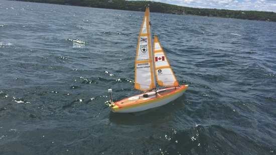
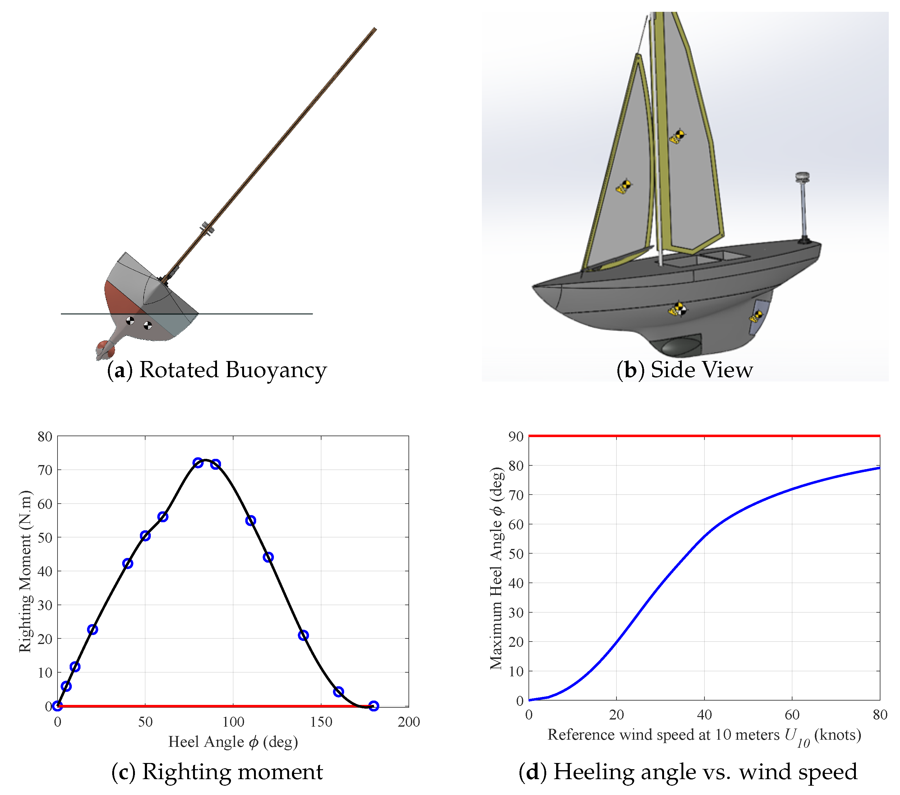
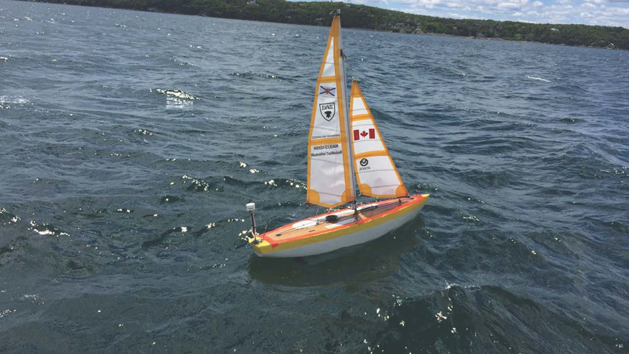
2. Sailboat Characteristics

In this section, specific characteristics needed for autonomous sailboats to complete a transatlantic trip across the ocean are reviewed.
The Microtransat is a challenging project for naval architects and engineers, since it requires the integration of several sub-systems on an autonomous controller. There are two ways to complete the challenge. In the initial definition of the competition, the trip was defined from east to west. It was later expanded with a second option from west to east. For naval architects, the two options require very different solutions. Indeed, the main winds and currents come from the west. Therefore, sailboats designed to go from Europe must have strong performance upwind. In comparison, the performance for a sailboat designed to start from America must be designed to be robust, and the vessel is helped by the main winds and current of the Gulf Stream. Nonetheless, the sailboat must get out of the Labrador current to reach the start line and reach the Gulf Stream. Furthermore, near the end of the race, classical strong south west winds can deviate the boat from the planned trajectory towards the north.
In Table 1, the engineering characteristics for selected past participants is summarized. In addition to the SeaLeon, there are a few notable designs: in 2019, Open Transat travelled 6041 km in 185 days; ABoat Time, a vessel constructed by the United States Naval Academy, has participated in the competition four times, and EC Crossing, launched in 2019, is a very small and light design that relies solely on solar energy.
When the SeaLeon was designed, the team built from the experience gathered while re-building the Breizh Tigresse. In fact, the Breizh Tigresse utilized an Ensta-Bretagne design, the Breizh Spirit [18], that was originally launched off the coast of France in 2011 and 2012. As such, it is important to first review the design of the Breizh Tigresse.
The hull of the Breizh Tigresse was the same as the one of the Breizh Spirit, but it was extended to provide protection to the rudder system and additional buoyancy to compensate for a heavier displacement. The hull was inspired by the transoceanic racers (Volvo Ocean race, Vendee Globe, Mini Transat). A quick analysis of the existing designs shows that the beam to length ratio decreases with the size of the boat. A linear regression was carried out to find the best ratio at the scale of the Breizh Tigresse. At the end, the length and beam of the vessel were 1.44 m and 0.55 m, respectively. Because of the wide hull, a double-rudder arrangement was chosen for the steering. The rudders were made of Ultra High Molecular Weight PolyEthylene (UHMWPE), which allows very high elastic deformations and high loads. It was a deliberate choice to opt for a smaller design than allowed by the Microtransat rules. First, a design that was small and light enough to avoid any risk of causing damage to other boats in case of collision, was desired. Second, to obtain a robust design, numerous tests were required (see Section 5.1) which led the team to design an object that would fit in the trunk of a car.
To maintain good stability and speed, a deep straight 5 kg bulb keel was designed. The final boat displacement with the payload was about 13 kg for the Breizh Spirit. It increased up to 28 kg for the Breizh Tigresse with the decision to replace the solar panels with batteries for reliability reasons. In the literature, this keel design is feared to catch algae. However, during the six years of testing with this keel design, the boat was never caught for more than a few minutes.
For the rigs and sails, the approach was to choose a well-proven system. Specifically, techniques applied in Remote Control Sailboat Racing were chosen and a 0.72 m 2 Marblehead C-rig, designed for high winds, was selected. A British sail manufacturer, SAILSetc Ltd. located in Essex, England, built a reinforced rig specially designed for the Microtransat. During the 2012 Breizh Spirit attempt, it was observed that the very high-performance membrane sail material chosen by the manufacturer did not withstand the two gales above 50 knots in wind. Thus, the Breizh Tigresse was equipped with a Dacron fabric. This material is heavier and prone to deformation which affected the performance, but it presented a better resistance, especially to flapping.
Contrarily to both former designs, the SeaLeon was designed for west to east crossing with favorable winds and currents. As stated earlier in this section, the performance is not as important in this direction and allows the design team to present a more conservative and robust design. The hull is designed from a model representing the Manitou, John F. Kennedy’s Presidential yacht, which was a cutter-rigged Bermudan yawl. The Manitou was a performance cruising yacht that would race well under heavy and light conditions, and the intent of the SeaLeon was to recreate its handling on the ocean at a smaller scale. From the Manitou lines, additional deck height and keel surface were added to give, respectively, increased interior volume and course stability. The SeaLeon is a 1.8 m vessel, with a beam of 0.5 m, and a draft of 0.4 m. The main sail and jib were fabricated using Hydra Net cloth by Michele Stevens at Sailoft Ltd in Lunenburg Nova Scotia. Hydra Net is supposed to be stronger, stiffer and lighter than the Dacron fabric used in the previous attempt. Similarly to the previous two designs, a loop rig with a single actuator controls both sails.
With regard to the energy supply, a difficulty in waterproofing the solar panels was observed during the Breizh Spirit mission, and this was attributed in part to the fact that the impact of waves on the deck can produce very high pressure. Additionally, the boat can be subject to collision with floating objects, including containers, ships, and wreckage. In fact, during tests, seagulls were seen plunging on the boat, as well as dolphins swimming around it. In short, even with the greatest attention paid to waterproofing the drone, the occasions that caused damage were also numerous.
It should be noted that for navigation, a lamp resistant up to 10 bars was included on the Breizh Tigresse; it was tested in a hyperbaric chamber at the IFREMER facilities in France. During the 2011 Microtransat attempt, this lamp housing was damaged, leading to a short circuit, which emptied the batteries. From this, it was decided to create an independent supply circuit for the lamp. It could be argued that different electrical sub-systems should be supplied independently.
Finally, Breizh Spirit’s attempt in 2012 showed corrosion attacks on any exposed circuit, particularly the solar panel. As such, in 2015, it was decided to avoid solar panels, and the Breizh Tigresse was powered with a non-rechargeable battery pack with a capacity compatible with the full energy budget of the Microtransat.

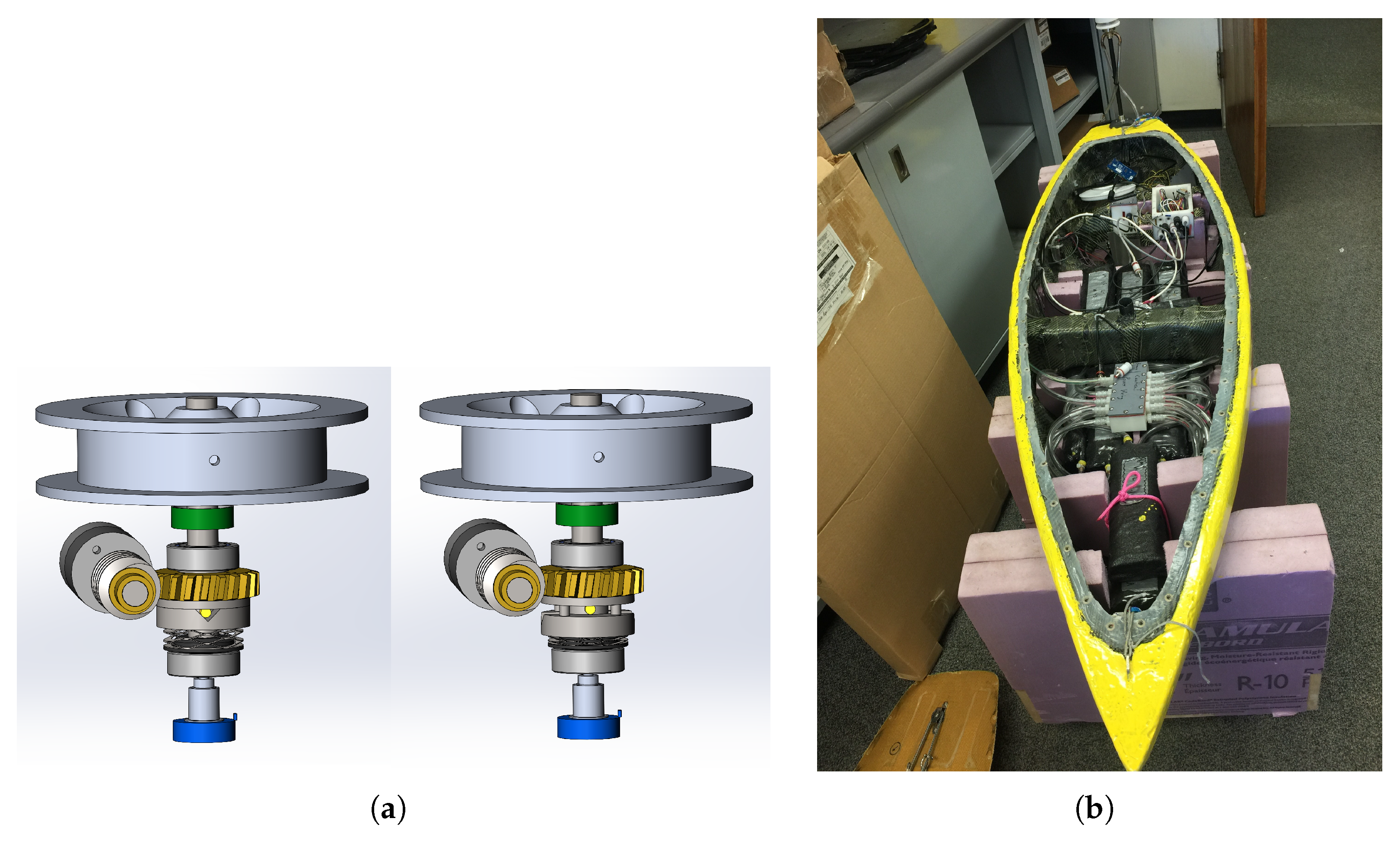
3. Mechanical Design

This section describes a robust mechanical design for a small autonomous sailboat intended to cross the Atlantic autonomously. To assess navigation ability in a wide range of conditions, the heel angle is predicted as a function of wind speed. Furthermore, the motor control system is described to minimize energy consumption. Finally, the boat fabrication process is summarized.
In order to determine the vessel’s angle of heel at sea, both the experienced wind and the boat’s resistance to heeling must be known. Pilot charts with average monthly wind information are available for the Atlantic (https://msi.nga.mil/Publications/APC, accessed on 29 August 2021), outlining the expected range of wind speeds for a given course over a reasonable time frame. However, almost all weather data are taken in freely moving air 10 m off the water surface. The height of the center of the sail plane ( h C E ) for the SeaLeon, as drawn in Figure 1b, is only 65.5 cm above the surface. At this height, wind shear reduces the apparent wind from the free air speed. Using the ITTC standard power law [19] or a logarithmic wind shear model [20], the reduction in wind speed can be calculated. At this height, the reduction is reasonably approximated by taking, respectively, either 75 or 68% of the forecast speed.
Next, for the modeled hull, the locations of the center of mass ( C M ) and center of buoyancy ( C B ) were found using SolidWorks for varying heeling angles equal to ϕ = 0 , 5 , 10 , 180 . The horizontal distance, or Righting Arm ( R A ), between the center of mass and the center of buoyancy (for example, shown in Figure 1a) defines the righting moment along with the mass of the sailboat. The results using a spline fit are shown in Figure 1c. The hull of the final design predicted positive righting moment up to 171 degrees, with very little negative stability. This intersection was interpolated, but was so far beyond operational heeling angles that providing a more accurate estimate was not pursued.
Using the calculated reduced wind speed as well as the necessary righting moment in Figure 1c allows the expected angle of heel to be found in Figure 1d. This model uses the area of the sails to obtain the maximum heeling combination for a given wind speed. The relationship between the wind speed and effective pressure used is
P = 0.5 ρ a i r V w 2 C S F ,
where ρ a i r is the air density, V w the wind velocity and C S F the side force coefficient. Claughton [21] and the ORC documentation [22] quote a maximum value of C S F approximately equal to 1.3 . Therefore, the relationship between U 10 , the standard reference wind, in m/s, at 10 m above the sea, and the heel ϕ plotted in Figure 1d is given by:
U 10 = 100 h C E 2 cos 7 ( ϕ ) ( 1 14 ) 4 Δ RA ρ a i r SA C S F ( T + 2 h C E ) .
The term in cos 7 ( ϕ ) is due primarily to the classical aerodynamic assumption that the component in the span direction (i.e., mast direction) has no significant influence on the side force. To a lesser extent, it is due to the variation of the altitude of the sail’s center with the heel. As can be seen in Figure 1d, the maximum heel angle remains below 20 in winds up to 20 knots and it remains under 40 up to 30 knots, which shows good dispositions for ocean voyages.
The motor design took into consideration the operating conditions of the sailboat, and considerable power and construction savings were found by disabling the motors, particularly in extreme conditions. For this purpose, a set of clutches was designed into the rudder and sail winch drives. First, a worm gear transmission was used to eliminate static power draw when the position of the rudder or sails was not commanded to change. This is a big advantage over the typical servo-based motors utilized in small autonomous sailboats. Secondly, between the worm gear and output shaft, a clutch was designed using a radial v-notch interfacing with a cross pin, as shown in Figure 2a.
The use of the clutch gave a positive hold until it was overpowered, at which point it could slip relatively freely. When loads decreased, the output pin could re-seat in the notch and control was re-established. The position feedback for the controls were attached on the output shaft, unaffected by the clutch state. Additionally, both the rudder and sail systems were mechanically limited so they did not overtravel the feedback potentiometers. In the case of a clutch slip, the control algorithm was programmed to only attempt to restore the position for a finite time, then wait before trying again. This way, the motors would not run continuously using power with little to no control gain.
The final hull, shown in Figure 2b, was constructed in a mould. It was made of a Kevlar–Carbon hybrid cloth, with foam ribs and internal bracing for additional structure. A lead keel was fully integrated into the hull to prevent getting caught in algae and seaweed. A drawing showing the location of the keel, the rudder, and windvane is shown in Figure 1b. Figure 2b also shows the power supply junction box and the controller box. The main deck closed the sailboat hull, and was sealed prior to the final launch.

4. Electrical System

In this section, first, in Section 4.1, an energy efficient real-time embedded system is described; then, in Section 4.2, alternative power supply solutions are proposed to maintain a balanced energy budget.

4.1. Real-Time Controller

In this section, first, a choice of low-power sensors is justified; then, the embedded processor software architecture is described; finally, the navigation algorithm is detailed.
In order to navigate, autonomous sailboats require a number of sensors, specifically a Global Positioning System (GPS) sensor to provide real-time position, a compass that provides vessel heading, and a wind vane that returns the wind direction. The physical sensors for the SeaLeon were the same models as for the Breizh Tigresse, since they were chosen very carefully to minimize power consumption, as is reported in Section 4.2. Specifically, the GPS was a breakout board distributed by Adafruit; it includes an on-board patch antenna, consumes extremely low power, and provides high sensitivity. It includes the GSM MTK3339 chipset and is interfaced to the controller using a USART (Universal Synchronous and Asynchronous Receiver and Transmitter). The compass was the HMC6343 by Honeywell, and provides a three-axis magneto-resistive sensor. It is interfaced to the controller using an I2C interface. Both the GPS and compass were strategically mounted inside the hull of the SeaLeon. A CV7 windvane manufactured by LCF uses ultra-sonic measurement to provide a reliable estimate of the wind direction. It was mounted on a short mast at the back of the hull, and was connected to the controller through a USART interface.
Additionally to the three sensors, the SeaLeon used an XBee Series 1 radio module for testing purposes, as well as the XEOS Onyx Iridium Asset Tracker to track and transmit the location of the sailboat. Note that during the mission, the XBee radio was disabled, and the XEOS was powered independently.
The rules for the Microtransat indicate that the sailboat must navigate autonomously. As such, to define a mission, waypoints are uploaded to the sailboat before the competition begins through the radio interface. Therefore, the SeaLeon had a waypoint loading mode, where the waypoints could be input to an electrically erasable programmable read-only memory (EEPROM) interfaced to the sailboat microcontroller. When a waypoint is reached, the next waypoint index is updated in an external EEPROM, in case there is a power failure during the mission.
Due to the metallic structures on the sailboat, especially the XEOS ONYX trackers, there was large magnetic interference with the compass. Prior to the final voyage, calibration was carried out for the Breizh Tigresse to correct for the compass considering the magnetic interference. During the calibration, angle readings were taken with the compass while the compass was turned in each 30 degree increment. The average angle was taken from three trials and compared to the actual angle, and the output served to populate a lookup table. From this information, the magnetic deviation could be calculated and was included in the code to obtain the heading with respect to true north. The final correction also included a correction that accounts for the magnetic declination between the true north and the measured north from the compass ϕ c , which is a function of the longitude L in degrees and can be estimated to be equal to ϕ c = 0.3 L 1.3 in the North Atlantic Ocean.
The SeaLeon used one microcontroller to receive sensor data, control the motors for navigation, and communicate its location. In comparison, the previous version of the sailboat, the Breizh Tigresse, used two Microchip PIC18F2550 microcontrollers to implement the sailboat controller. The main PIC was responsible for receiving data from its peripherals, applying an algorithm, and then sending that data to the second chip. The secondary chip was only responsible for converting the motor position to a pulse width modulation (PWM) signal applied to the servo motors. The choice to integrate the motor control and the sensor acquisition system was made to reduce the number of peripherals, as well as the power consumption. The SeaLeon controller was implemented using a 32-bit SAMD20 microcontroller from Microchip that features an ARM Cortex-MO processor, and can easily interface to peripherals through multiple USART and I2C compatible pins.
The software implemented on the microcontroller is modular and has a hierarchical design with three layers: an input/output layer, a task layer, and a control layer. A hierarchical design was chosen because of its adaptability, due to the separation of hardware specific drivers from high-level logic. Specifically, this architecture allows the easy integration of new devices, since the same control layer can be used, and only the input/output layer should be updated.
The input/output layer includes device drivers for all of the peripherals used for the SeaLeon. These include the USART, the I2C bus, the analog-to-digital converter (ADC), and the pulse width modulation (PWM) generator. The task layer contains the high-level modules that control the peripherals. The control layer is responsible for managing the state of the sailboat and performing tasks at periodic intervals.
To handle the multiple tasks, a clock interrupt handler expires every 200 milliseconds. When the handler is triggered, custom coded tasks are called, each at a unique period, as summarized in Table 2. This allows the controller to read the sensors, log the data, and control the motors at a pre-configured rate. In a future software design, the tasks running on the controller can be defined using a real-time operating system such as Free RTOS that is compatible with the ARM processor chosen. This can identify different levels of priorities for the tasks, and can be programmed to sleep to further reduce the energy consumption of the microcontroller.
The sailboat has two data logging modes: test and deploy. In test mode, the data are sent using an Xbee Series 1 radio module. The data can then be visualized in real time to a host computer for processing. The system logs sensor data including GPS coordinates, wind direction, and compass readings. It also logs controller data such as the next waypoint, the course selected by the navigation algorithm, and the rudder and sail positions. In deploy mode, data are sent less frequently via an XEOS Onyx device that communicates over the Iridium network. Log messages from the XEOS Onyx device are logged to a remote server. The data can then be viewed through a web client provided by XEOS.
To enter the waypoints, a graphical user interface on a host computer is used to define the waypoint characteristics and send them to the EEPROM. For this purpose, the microcontroller regular navigation mode is interrupted and changed to a waypoint load mode. In this mode, a waypoint entry can be sent to the sailboat which indicates the waypoint index, the GPS coordinates of the waypoint, the waypoints threshold radius, and the index of the next waypoint in the path.
One of the most critical functions of the controller is the navigation algorithm, shown in Figure 3a. This algorithm uses information from all of the sailboat’s peripherals, as well as the waypoints from the EEPROM. The goal of the algorithm is to determine how to update the rudder and sail to make the sailboat reach the waypoint. Each waypoint has a threshold radius that is indicated when uploading the waypoint to the EEPROM. When the distance between the boat’s position and the waypoint is within the threshold radius, a validation counter is incremented. After five consecutive readings within the waypoint threshold radius, the algorithm advances to the next waypoint.
The course selection is chosen to be the bearing between the boat’s current position and the target waypoint. However, there are situations when the direction of the wind may make it impossible for the sailboat to go in that direction. The sailboat cannot travel in the direction directly opposite to the wind. Instead, the sail boat must tack back and forth to make forward progress. As shown in Figure 3b, the sailboat must bear down when its direction is within a dead-zone, defined to be when the sailboat is against the direction of the wind ± 45 . Similarly, the sailboat luffs when it sails directly downwind, i.e., 180 ± 10 . Otherwise, four fixed sail settings are defined depending on if the sailboat is at close haul (below 60 . 0 ), close reach (below 75 . 0 ), beam reach (below 90 . 0 ), or broad reach (below 135 . 0 ). A similar algorithm is described in [18].

4.2. Energy Supply

Due to the duration of the Microtransat Challenge, an energy budget must be estimated such that the vessel can cross the ocean autonomously. Ideally, the drone’s lifetime is infinite, which can be assured using rechargeable batteries. However, the effectiveness and likelihood of failure of the energy supply system must also be considered. In this section, the choice of a non-rechargeable energy source for the SeaLeon is justified.
Note that several attempts were made to cross the Atlantic. The energy supply for some of the most competitive designs is summarized in Table 3, along with the number of days lasted at sea. It should be noted that the mission duration seems to have been very short for sailboats relying on rechargeable batteries.
In the design of the SeaLeon, the expected mission duration was approximately 90 days, with a fairly wide margin (plus or minus 30 days) depending on the sea conditions. In order to establish the energy supply requirements, Table 4 shows a calculated power budget for the SeaLeon. The power budget was made using estimates from data sheets and actual measurements when possible. Note that in the design of the SeaLeon, the Iridium communication system was a standalone radio, with an independent battery.
The SeaLeon’s power system was designed to give as many amp hours as possible given the constraint of the size of the sailboat. This idea led to a power system consisting of 128 Lithium Thionyl Chloride ( LiSOCl 2 ) D-Cell batteries, distributed by Eagle-Picher. The batteries were placed in series giving a supply voltage of 14.8 volts, and thirty-two sets of four were placed in parallel in order to increase the amp-hour capacity. Altogether, the batteries provided a total of 680 Ah capacity.
Rechargeable methods for supplying power to the sailboat were also considered. Solar panels have been a popular choice for other Microtransat participants. For example, solar panels were used by the the Breizh Spirit, designed by Ensta-Bretagne. The Breizh Spirit had an energy supply that could last 3 days minimum, and used lead acid batteries that could be recharged up to 500 mA by solar panels.
In addition to non-rechargeable cells, rechargeable cells, such as lithium iron phosphate ( LiFePO 4 ) cells, are considered as an option to increase the lifetime of the drone. Table 5 shows a comparison of metrics for four LiSOCl 2 versus four LiFePO 4 cells placed in series. An arrangement of eight 280 Ah prismatic ( LiFePO 4 ) cells with two sets of four placed in parallel can provide 560 Ah of capacity and the ability to increase the amp-hours further by recharging the cells. However, from the table, it is apparent that LiSOCl 2 PT-2300 batteries weigh less and occupy less volume per amp-hour in comparison to the LiFePO 4 LF280 cells. The LiSOCl 2 PT-2300 cells were chosen for the SeaLeon energy supply based on its comparison to the rechargeable cells. In addition, a rechargeable method such as solar panels would take up a significant amount of space on the sailboat. It was decided that a larger density of cells would be the best approach to a long-lasting energy supply.
Rechargeable lithium cells do provide an interesting alternative solution, particularly for sustainability considerations. Specifically, rechargeable batteries are more convenient for testing purposes, since they can be recharged rather than removed and replaced after trials. Rechargeable lithium cells also create the potential for a higher effective capacity when paired with renewable energy such as solar panels. In addition, the use of renewable energy can lead to research into software power conservation techniques. The Breizh Tigresse, for example, used a charge controller to turn off the electronics and actuator power when the battery voltage was lost. The boat was programmed to act like a drifting raft in this case. Adjustments could also be made to have the sailboat enter a ’recharge mode’ when the battery voltage drops below a certain level, and would limit the boat’s daily consumption of power.

5. Testing and Navigation

In this section, a robust testing strategy is described in Section 5.1, the importance of collision avoidance is detailed in Section 5.2, an optimal route to complete the west to east crossing is proposed in Section 5.3, and in Section 5.4, the SeaLeon’s mission achievement is summarized.

5.1. Testing Strategy

Robustness is a key point for the Microtransat Challenge. Each part of the boat must be carefully designed, built, and tested. To enhance reliability, the system must be kept as simple as possible, and the number of parts reduced as much as possible to reduce the failure probability. For every part and every part modification, there are several levels of tests to pass. The validation process consists of nine test types to be run in succession.
The first step consists of unit tests run using the simulation of an electronic component, and must be accomplished for any increment in the controller software or any change in component. The objective is to verify that the component reacts as expected to any given entry. The second step consists of verifying a model of the integrated system. The components are integrated in all or part of the system and tested in realistic conditions to verify functional specifications. Simulations are also used to predict the expected behaviour of the mechanical design. For example, the load can be estimated for a new rudder design, as explained in [18]. Hardware in the Loop (HIL) can be advantageously implemented during this step to evaluate all supply chain [23]. This leads to the third and fourth validation steps, which are, respectively, the unit test and the integration test in laboratory. Then, the fifth step is conducted outdoors, ideally in a large open space free from any interference. A soccer playground was utilized for this during the design of SeaLeon, and the boat was installed on a trolley. Navigation was emulated by controlling the different sensor inputs manually, and the system reaction, such as the sails or the rudder angles, were observed and verified.
During the sixth step, navigation on water is assessed in light winds at less than ten knots, and a predefined path is programmed with waypoints. The chosen location must be inshore and allow easy recovery. For the design of the Breizh Tigresse and SeaLeon, the Northwest Arm in Halifax was particularly suitable for these tests, and the boat’s ability to maneuver in any directions at any point of sail was assessed using three waypoints configured at three vertices of a triangle with approximately 150 m separation between the waypoints. During this step, the maneuvering qualities and ability to tack and jibe without difficulties are also tested. The next two test series consist of strong wind tests. Here, the robustness of the design is confronted with a real situation. First, these tests can be conducted inshore, in a lake or harbor, then in high sea to additionally assess the resistance to hydrodynamic loads with high waves. Finally, the ninth step is the endurance test, which is the most costly, because it requires the mobilization of several team members and material for several days. In fact, a chase boat able to operate in rough sea is needed to follow and recover the drone. In this last stage, the resilience of each part is tested. It is very important to note that, at this point, it is possible that the entire vessel is lost; therefore, it must only be conducted after successfully passing the eight former steps.
For the Breizh Tigress, the hull was provided by Ensta-Bretagne. Several components of the sailboat needed to be rebuilt, including the rigging and sail, as well as the power supply and controller. After having completed the design and tested all the individual components, several tests were run on the water, including short-term navigation tests in Halifax’s Northwest Arm. Furthermore, a 2-day endurance test was run off the coast of Halifax. A total of four months were required for the re-design, testing, and launch of the Breizh Tigress.
Following the launch of the Breizh Tigress, almost two years were required to design and launch the SeaLeon. Note that it was important to time the launch of the sailboat to avoid hurricanes that are frequent in North America in the fall season. A similar testing procedure as for the Breizh Tigresse was adopted. Note that during dry land tests, the entire boat with sails was mounted in the back of a truck navigating a set of pre-programmed waypoints located around Dalhousie University. It was possible to monitor the performance from inside the truck through the radio to confirm waypoint validation as well as navigation, wind, and rudder information. Following these these tests, similar tests as those that were run with the Breizh Tigresse on the Northwest Arm were run. A few tests were run in stronger wind conditions and various sea states in the open sea to analyze the boat’s behaviour. These tests were encouraging, with the hull remaining stable on the waves and the only downside being unavoidable: wind shadow from upwind waves in steeper chop.
A comparison of the routes taken by the Breizh Tigresse and SeaLeon is shown in Figure 4 and will be analyzed in the next section.
An important difference between the Breizh Tigresse and the SeaLeon was the motor design. For the SeaLeon, a clutch was used to prevent the motors from being overpowered. During initial testing, it was observed that the sail control clutch actuated frequently. Sudden wind gusts activated the clutch, and in these conditions, the motor could pull in the sail to the desired position after a delay. This limited the peak loads that the sail sheeting system could experience. To reduce the sensitivity of the clutch, the winch drum diameter was reduced from 7.6 cm to 4.8 cm. As a consequence, this increased the wind loads that were required to decouple the motor and sail control. In addition to the reduction in power consumption, there was a gain in resolution for sensing the sail position. This was measured on the drum shaft using a potentiometer.

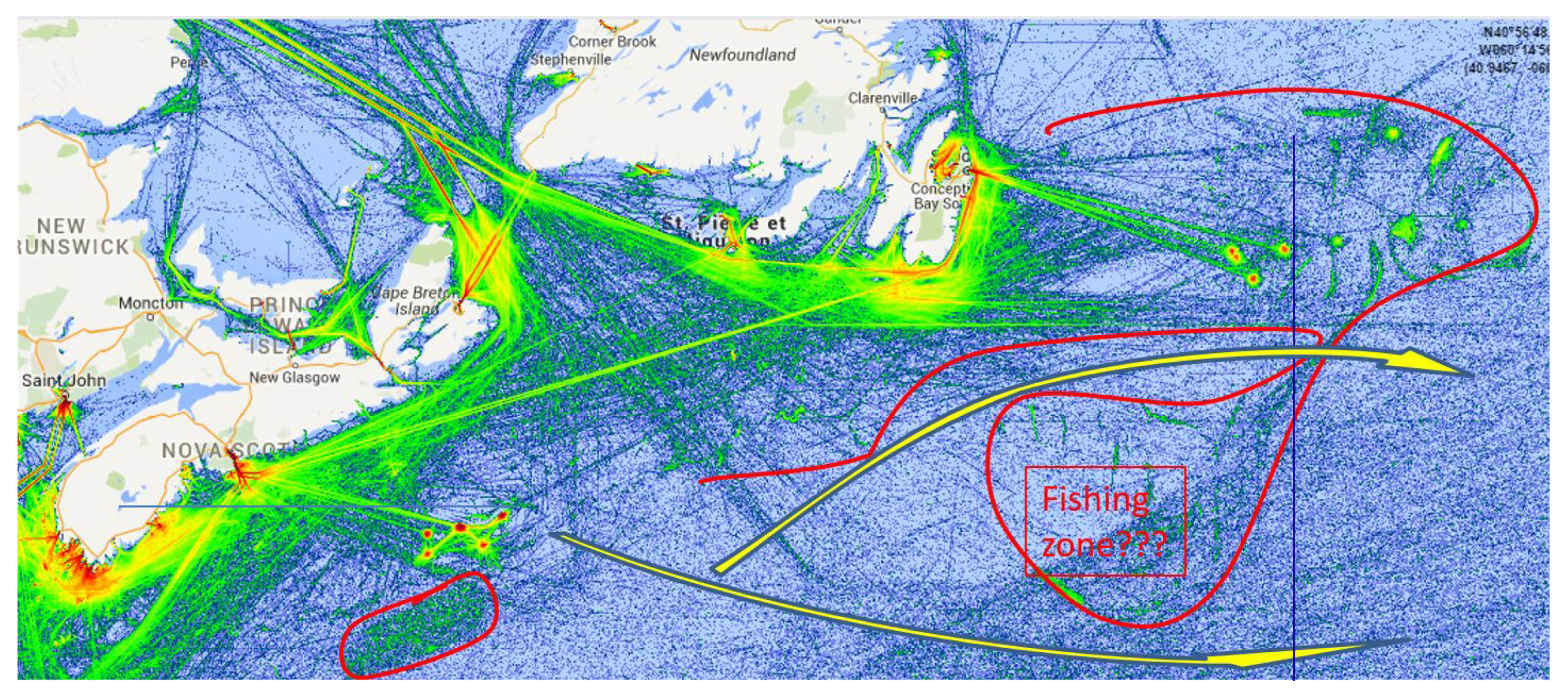
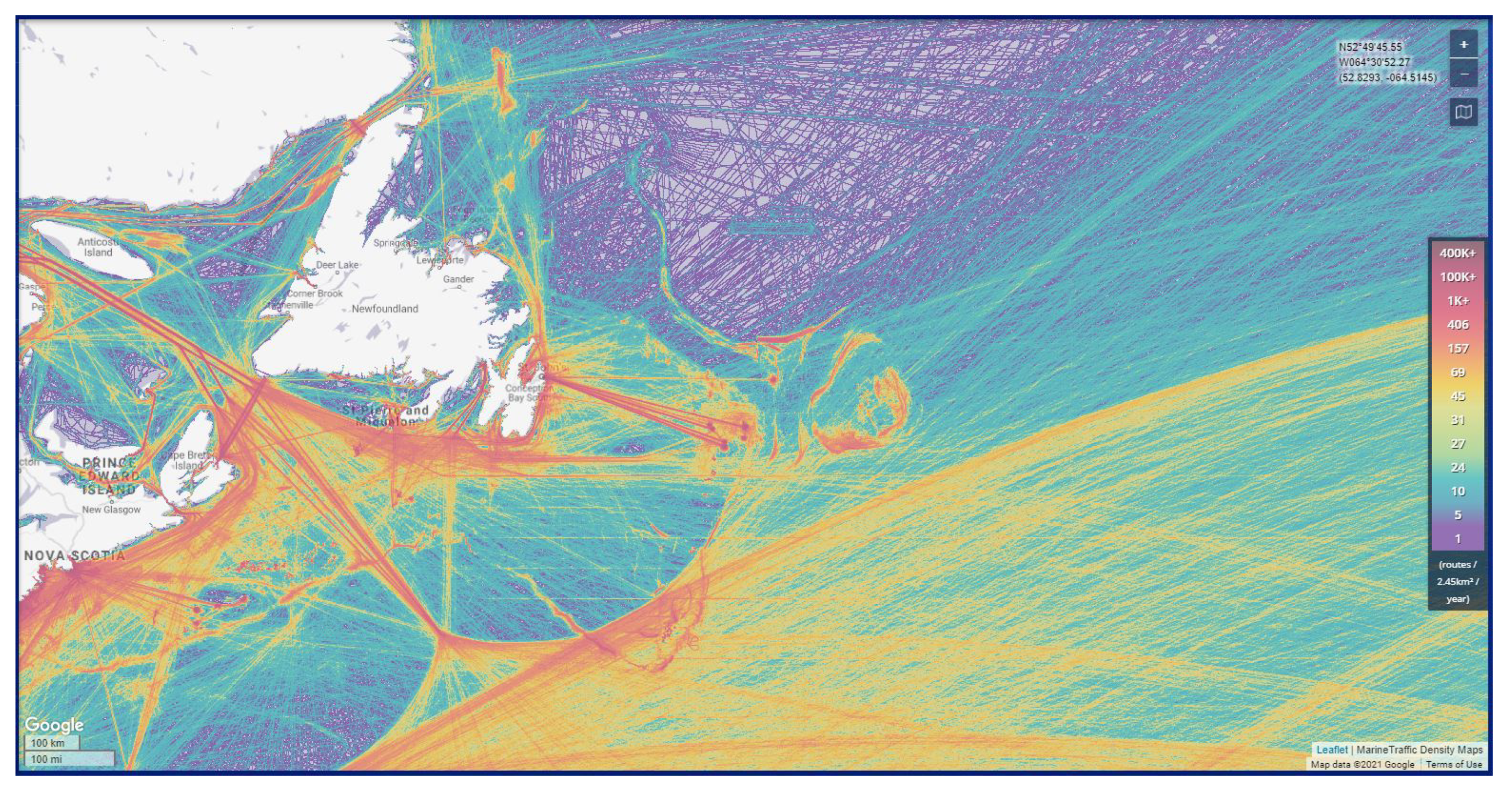
5.2. Collision Avoidance

There are a number of potential risks for collision during a transatlantic mission. In this section, the importance of preventing collision is discussed, and an overview of techniques that can be adopted to mitigate the risk is provided.
A prime example to explain the importance of an anti-collision system is what is believed to have happened to the Breizh Tigresse during its mission. On September 7, 2015, 14:00 UTC, after having validated waypoint number five shown in Figure 4, the NYK DIANA, a 300-meter-long container ship, crossed the trajectory of the Breizh Tigresse. After that time, the Breizh Tigresse velocity made good (VMG) dropped by 66%. At the same time, the standard deviation in heading angle increased by 49%. As such, there is a strong suspicion that collision occurred with a ship. It is interesting to note that the route taken by the container ship was not clearly visible in the density map by marine traffic in 2015, as shown in Figure 5; however, it appears clearly at the north of Sable Island in the 2018 version, represented in Figure 6.
In the 2018 version of this map, the contours of the Grand Banks of Newfoundland are clearly visible. This reveals the presence of intense fishing in these areas. Collision with fishing vessels or fishnets are unmistakably the most common reason for failure in the Microtransat’s history (https://www.microtransat.org/history.php, accessed on 29 August 2021). As such, these zones must be avoided as much as possible. In Figure 5, yellow arrows show two ways to avoid the main fishing areas. Detouring the Grand Banks to the south seems a good option. However, this causes the drone to enter the main commercial northern route from America to Europe. Therefore, for the SeaLeon, the second option through the Grand Banks was chosen. While the path is narrower, it keeps drones away from the main traffic until Europe is reached. Given the deviations from the route observed in Figure 4, the narrowness of the path used may legitimately raise questions. Just after validating the ninth waypoint, the SeaLeon trajectory can be observed several times crossing the southern Flemish Cap limit in an intense fishing zone, as shown in Figure 6. This could be where she received damage, as it remains unclear if the next waypoint was ever validated and the trajectory soon became erratic. Participating in the Microtransat Challenge under these conditions may seem like a lottery. It is worth identifying alternatives, other than increasing the number of waypoints locally and reducing the validation radius.
The first alternative to mitigate collisions is undoubtedly to build a ship capable of withstanding the shock. This is a strategy that has been adopted with limited success. The SailBuoy team actually conducted real-life collision tests (https://www.youtube.com/watch?v=wMbAxejIDAM, accessed on 29 August 2021). However, as Dhomé points out, such robustness limits the sailing abilities [24]. As such, other solutions must be considered. An efficient anti-collision system requires the design of three subsystems:
(1)
A risk assessment system to avoid the anti-collision system being permanently on alert and consuming unnecessary energy [25];
(2)
An algorithm that defines avoidance solutions according to the situation [26];
(3)
A realistic simulator that can validate the complete system before expensive sea trials [27], while keeping in mind an important observation made by Schlaefer in 2011 that “anti-collision usually works in simulation but in real world never” [26].
Anti-collision systems remain in the realm of research, even though an important effort has been seen in recent years with increased interest in autonomous ships. There are two main factors that make the problem all the more difficult in the Microtransat Challenge. The first is that it is difficult for a ship to avoid another ship that is typically going 10 times faster. It may be feasible to avoid merchant ships that have regular routes, but for fishing vessels whose trajectories are much less predictable, it becomes very difficult [25]. The difficulty is compounded when the other vessel makes an intentional maneuver. The second is the energy cost of such a system. Power is required for the additional sensors as well as for the actuators that are needed for the additional maneuvers. Specifically, additional computational resources are required to run the avoidance algorithms, and the route travelled is extended to avoid obstacles.

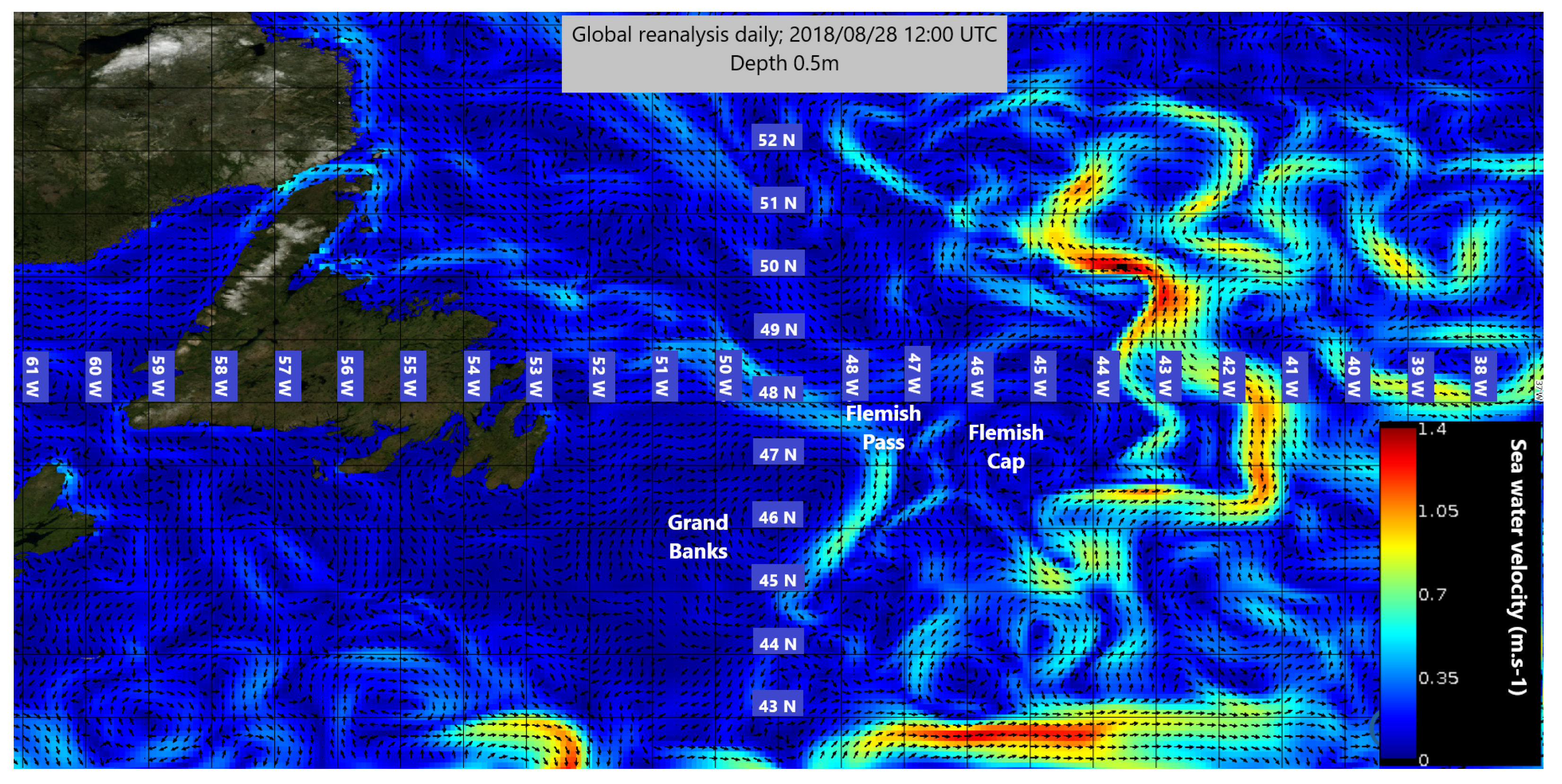
5.3. Path Planning and Weather Routing

Given the starting and finishing line defined by the Microtransat organization, it is interesting to note that the northern route from the northernmost point of the starting line to the northernmost point of the finish line is 50% shorter than the southern route. This gives a tremendous advantage to the northern path. SBmet, which is the only boat so far to ever complete the Microtransat Challenge in the unmanned category, chose the northern route. However, sending the boat to the north point of the starting line as well as recovering it at the northern point of the finish line requires a significant budget and means. In 2015,the Breizh Tigresse was launched just a few miles from Halifax. In comparison, Sealeon was launched from Cape Breton, which resulted in a significant gain of about 140 NM. Additionally, this last option avoided the marine traffic from Halifax. Both routes meet off Sable Island at the edge of the continental shelf. Then, both routes follow the north option depicted in Figure 5 and described in Section 5.2. Off the Grand Banks of Newfoundland, the route follows the great circle route up to a target point located on the finish line in the west of Brest, France.
Weather routing aims to define the optimal route and to estimate the energy budget needed to complete the Microtransat Challenge [28]. Since the maximum forecast prediction period available is 16 days, it is necessary that the rest of the journey is predicted using pilot charts. The simulation was performed with Opencpn software. This software includes a simple Velocity Prediction Program (VPP) that gives a rough assessment of our design. The simulation results were consistent with the performance measured at sea for the Breizh Tigresse. The resulting polar speed diagram with respect to True Wind Angle (TWA) and True Wind Speed (TWS) is shown in Table 6. The weather routing showed that the wind appeared to be strongest on the northern route. Correspondingly, the average boat speed was lower on the southern route. However, simulation results were quite close (1.47 vs. 1.43 knots in boat speed and 7.23 vs. 7.19 knots in wind velocity). As such, the route was defined to avoid traffic lanes and fishing zones as much as possible.
It is interesting to compare the routing analysis with the performance that was observed at sea. These speed predictions are rather pessimistic compared to the measures at sea. Indeed, during the first week of the 2015 challenge, the Breizh Tigresse achieved an average speed about 1.70 knots. However, the averaged velocity made good (VMG) was 1.40 knots, which is quite close to the predictions. This loss of 18% between the actual boat velocity and the velocity projected on the aimed direction (i.e., VMG) should be considered in future designs. This is relevant for a better energy budget prediction and can also contribute to a more accurate control system.

5.4. Achievements

A comparison of the SeaLeon and Breizh Tigresse performance is of great interest, since the mechanical design of the two vessels had important differences. In the span of one week, the Breizh Tigresse travelled 230.0 NM in terms of VMG while Sealeon sailed 922 NM in 28 days for a weekly average of 230.5 NM. For SeaLeon, the launch date was chosen with a particular attention to the weather forecast. The drone made its best 24 h performance on the first day, with 55.8 NM travelled for a speed average of 2.32 knots at the top speed of the velocity polar diagram (Table 6). A Froude similarity was applied and demonstrated that SeaLeon should have been expected to be 12% faster. However, the average performance for both vessels was close despite the difference in size. In practice, this is partly due to the more efficient hull of Breizh Tigresse and the fact that SeaLeon was slightly underpowered, as it inherited the same sail plan as Breizh Tigresse despite an 80% higher displacement. During the mission, the Breizh Tigresse showed a top speed of 6.6 knots, while SeaLeon achieved a top speed of 6.0 knots. This may be explained by the surfing qualities of the first hull. A good behavior in rough conditions and the ability to keep the trajectory under control may influence the choice of hull design to avoid high hydrodynamic loads. However, such performances are too rare to be conclusive.
It is interesting to note that during the SeaLeon’s mission, the currents had a significant impact on its route. Figure 7 shows the sea surface water velocity on 28 August 2018. The limit between the Grand Banks and the Flemish Cap can be seen with the Labrador current from the north to the south in light green while engaging into the Flemish Pass. To the east of the Flemish Cap, between longitudes 42° W and 45° W, a deviation of the Gulf Stream towards the north can be observed. The current in this area can reach 1.4 m/s, twice the average VMG of SeaLeon. In fact, the Gulf Stream trajectory matches the SeaLeon trajectory towards the North well at that position in time. The same trajectory pattern was also observed at the same location by Andy Osusky with OpenTransat in 2019 (https://track.opentransat.com, accessed on 08/29/2021).
It is, therefore, quite possible that, although the SeaLeon deviated by almost 200 NM north of its route, it was still under control until 20 September 2018, 41 days after its launch. The deviation towards the north visible on Figure 4 would only be due to the vigorous influence of the Gulf Stream. In fact, between 7 and 13 September, SeaLeon resumed its course towards the next waypoint with constancy. Given the strength and unsteadiness of the Gulf Stream, it is difficult to equate the erratic nature of the trajectory of the sail drones in this area with a system failure. Nevertheless, after 3 September, the VMG over 24 h fell by between 30% and 47%, even though the Gulf Stream is supposed to be favorable on average, particularly in this area.
With regard to the realized performance, the project can be considered to be very successful. Following up on previous attempts, originally with the Breizh Spirit in 2011 and 2012, then Breizh Tigresse in 2015, Sealeon improved the performance with a new record in time and distance covered by an autonomous sailboat in 2018. The SeaLeon’s voyage lasted 76 days before the final remote communication at LAT 45°30 30″ N, LON 34°32 30″ W. At the time, this was a record of endurance. After its last position report on 14 October, it was found on February 21st at Trahan Strand near Castletownbere, County Cork, Ireland. It is the first fully autonomous sailboat to complete a complete transatlantic journey from America to Europe in the context of the Microtransat Challenge.
The recovered hull was in one piece, but the sails were badly torn. It is still unclear what sub-systems failed during the voyage, and whether the failures were even mechanical or electrical. In order to achieve a better understanding of the failures, it is highly recommended that diagnostic messages are sent from the different sub-systems on a regular basis.

6. Conclusions

At Dalhousie University, the Faculty of Engineering launched a very successful program to design a small autonomous sailboat to cross the Atlantic, as part of the Microtransat Challenge. The project is currently led by engineering students, who are learning from experience how to optimize a sailboat for a long-term mission. Specifically, a robust mechanical structure, as well as the design of a controller for minimum energy draw, are taken into consideration. In this paper, the focus is on a comparison between the SeaLeon and her predecessor, the Breizh Tigresse. The SeaLeon’s hull was inspired by a cutter-rigged Bermudan yawl, and its behavior at scale was analyzed using CAD tools. The sail and rig were chosen to represent that of a traditional human operated sailboat, and the navigation control system allowed for an energy-efficient management of the actuators. To supply the electronics, high-capacity non-rechargeable batteries maximized the lifetime of the vessel. This was preferred over a rechargeable energy supply using a solar cell, as such systems remain unreliable when mounted on small sail drones. Finally, strong knowledge of navigation as well as a rigorous testing procedure were crucial for the success of the sailboat. It was found that the ocean conditions significantly impacted the trajectory taken by the SeaLeon, even as she remained under control. This will guide future designs for the Microtransat Challenge.

Author Contributions

Writing—original draft preparation, T.A.; mechanical, G.M.; electronics and software, T.A.; energy supply, A.W.; sailboat characteristics and navigation, K.R.; supervision, J.-F.B. All authors have read and agreed to the published version of the manuscript.

Funding

This research was funded by Ocean Frontier Institute Seed Fund: “Autonomous Sailboat for Remote Sensing”.

Institutional Review Board Statement

Not applicable.

Informed Consent Statement

Not applicable.

Data Availability Statement

Not applicable.

Acknowledgments

We would like to thank XEOS, the Dalhousie Faculty of Engineering, including former Dean Josh Leon, Jim Hanlon and friends at COVE, Rob Warner and Piotr Kawalec, the various students who supported the design (namely Andrew Dobbin, Thomas Gwynne-Timothy, Julia Sarty, Anthony Chalmers, Serge Toutsenko, Blake Meech, and Garrett Jenkins) as well as MAST led by Jade Farr for technical and financial support throughout the lifetime of this project.

Conflicts of Interest

The authors declare no conflict of interest.

References

  1. Olson, R.A. Communications Architecture of the Liquid Robotics Wave Glider. IFAC Proc. Vol. 2012, 45, 255–259. [Google Scholar] [CrossRef]
  2. Mullison, J.; Symonds, D.; Trenaman, N. ADCP data collected from a Liquid Robotics Wave Glider®. In Proceedings of the 2011 IEEE/OES 10th Current, Waves and Turbulence Measurements (CWTM), Monterey, CA, USA, 20–23 March 2011; pp. 266–272. [Google Scholar] [CrossRef]
  3. Mellinger, D.K.; Klinck, H.; Bogue, N.M.; Luby, J.; Matsumoto, H.; Stelzer, R. Gliders, floats, and robot sailboats: Autonomous platforms for marine mammal research. J. Acoust. Soc. Am. 2012, 131, 3493. [Google Scholar] [CrossRef]
  4. Mordy, C.W.; Cokelet, E.D.; De Robertis, A.; Jenkins, R.; Kuhn, C.E.; Lawrence-Slavas, N.; Berchok, C.L.; Crance, J.L.; Sterling, J.T.; Cross, J.N.; et al. Advances in ecosystem research: Saildrone surveys of oceanography, fish, and marine mammals in the Bering Sea. Oceanography 2017, 30, 113–115. [Google Scholar] [CrossRef]
  5. Gentemann, C.; Scott, J.P.; Mazzini, P.L.; Pianca, C.; Akella, S.; Minnett, P.J.; Cornillon, P.; Fox-Kemper, B.; Cetinić, I.; Chin, T.M.; et al. Saildrone: Adaptively sampling the marine environment. Bull. Am. Meteorol. Soc. 2020, 101, E744–E762. [Google Scholar] [CrossRef] [Green Version]
  6. Stelzer, R.; Pröll, T. Autonomous sailboat navigation for short course racing. Robot. Auton. Syst. 2008, 56, 604–614. [Google Scholar] [CrossRef]
  7. Miller, P.; Sauzé, C.; Neal, M. Development of ARRTOO: A Long-Endurance, Hybrid-Powered, Oceanographic Research Vessel. In Robotic Sailing 2013; Bars, F.L., Jaulin, L., Eds.; Springer International Publishing: Cham, Switzerland, 2014; pp. 53–65. [Google Scholar]
  8. Ferl, T.; Hills, S. A Control System for a Small Autonomous Sailing Vessel Paper. In Proceedings of the ASEE Zone I Conference & Workshop, Niagara Falls, NY, USA, 15 April 2019. [Google Scholar]
  9. Erckens, H.; Beusser, G.; Pradalier, C.; Siegwart, R.Y. Avalon. IEEE Robot. Autom. Mag. 2010, 17, 45–54. [Google Scholar] [CrossRef]
  10. Tretow, C. Design of a Free-Rotating Wing Sail for an Autonomous Sailboat. Master’s Thesis, KTH, Naval Systems, Stockholm, Sweden, 2017. [Google Scholar]
  11. Stelzer, R.; Jafarmadar, K. The robotic sailing boat asv roboat as a maritime research platform. In Proceedings of the 22nd International HISWA Symposium, Amsterdam, The Netherland, 12–13 November 2012. [Google Scholar]
  12. Ganoulis, E.; Alcantara, A.; Niedermaier, J.; Winn, R.; Jones, N.; Tur, A.M.; Blake, J.; Townsend, N.; Schillai, S. Peruagus-a Transatlantic Autonomous Surface Vessel for the Microtransat Challenge. In Proceedings of the 11th International Robotic Sailing Conference, IRSC 2018, Southampton, UK, 31 August–1 September 2018. [Google Scholar]
  13. Stenersen, H.S. Construction and Control of an Autonomous Sail Boat. IFAC-PapersOnLine 2016, 49, 524–531. [Google Scholar] [CrossRef]
  14. Santos, D.; Silva Junior, A.G.; Negreiros, A.; Vilas Boas, J.; Alvarez, J.; Araujo, A.; Aroca, R.V.; Gonçalves, L.M.G. Design and Implementation of a Control System for a Sailboat Robot. Robotics 2016, 5, 5. [Google Scholar] [CrossRef] [Green Version]
  15. Silva, A.G.d., Jr.; Santos, D.H.d.; Negreiros, A.P.F.d.; Silva, J.M.V.B.d.S.; Gonçalves, L.M.G. High-Level Path Planning for an Autonomous Sailboat Robot Using Q-Learning. Sensors 2020, 20, 1550. [Google Scholar] [CrossRef] [PubMed] [Green Version]
  16. Sun, Q.; Qiao, Z.; Strömbeck, C.; Qu, Y.; Liu, H.; Qian, H. Tacking Control of an Autonomous Sailboat Based on Force Polar Diagram. In Proceedings of the 2018 13th World Congress on Intelligent Control and Automation (WCICA), Changsha, China, 4–8 July 2018; pp. 467–473. [Google Scholar] [CrossRef]
  17. Sun, Q.; Qi, W.; Liu, H.; Sun, Z.; Lam, T.L.; Qian, H. OceanVoy: A Hybrid Energy Planning System for Autonomous Sailboat. In Proceedings of the 2020 IEEE/RSJ International Conference on Intelligent Robots and Systems (IROS), Las Vegas, NV, USA, 25–29 October 2020; pp. 2481–2487. [Google Scholar]
  18. Leloup, R.; Le Pivert, F.; Thomas, S.; Bouvart, G.; Douale, N.; De Malet, H.; Vienney, L.; Gallou, Y.; Roncin, K. Breizh Spirit, a Reliable Boat for Crossing the Atlantic Ocean. In Robotic Sailing; Schlaefer, A., Blaurock, O., Eds.; Springer: Berlin/Heidelberg, Germany, 2011; pp. 55–69. [Google Scholar]
  19. ITTC Quality Systems Group ITTC Symbols and Terminology List. In Proceedings of the International Towing Tank Conference, Copenhagen, Denmark, 31 August–5 September 2014.
  20. Association, D.W.I. Roughness and Wind Shear. Available online: http://xn–drmstrre-64ad.dk/wp-content/wind/miller/windpower%20web/en/tour/wres/shear.htm (accessed on 10 May 2021).
  21. Claughton, A. Developments in the IMS VPP Formulations. In Proceedings of the Fourteenth Chesapeake Sailing Yacht Symposium, Annapolis, MD, USA, 30 January 1999; pp. 1–20. [Google Scholar]
  22. International Technical Committee, Offshore Racing Congress VPP Documentation Guide. 2015. Available online: https://www.orc.org/rules/ORCVPPDocumentation2015.pdf (accessed on 8 August 2021).
  23. Sauzé, C.; Neal, M. Simulating Sailing Robots. In Robotic Sailing; Schlaefer, A., Blaurock, O., Eds.; Springer: Berlin/Heidelberg, Germany, 2011; pp. 113–124. [Google Scholar]
  24. Dhomé, U.; Tretow, C.; Kuttenkeuler, J.; Wängelin, F.; Fraize, J.; Fürth, M.; Razola, M. Development and initial results of an autonomous sailing drone for oceanic research. In Marine Design XIII; CRC Press: Boca Raton, FL, USA, 2018; pp. 633–644. [Google Scholar]
  25. Lee, M.K.; Park, Y.S.; Park, S.; Lee, E.; Park, M.; Kim, N.E. Application of Collision Warning Algorithm Alarm in Fishing Vessel’s Waterway. Appl. Sci. 2021, 11, 4479. [Google Scholar] [CrossRef]
  26. Ammann, N.; Hartmann, F.; Jauer, P.; Krüger, J.; Meyer, T.; Bruder, R.; Schlaefer, A. Global data storage for collision avoidance in robotic sailboat racing–the world server approach. In Robotic Sailing; Springer: Berlin/Heidelberg, Germany, 2011; pp. 157–166. [Google Scholar]
  27. Sauzé, C. ASVTrafficSim: A Simulator for Autonomous Surface Vehicle and Manned Vessel Collisions. In Robotic Sailing; Springer: Berlin/Heidelberg, Germany, 2018; pp. 63–67. [Google Scholar]
  28. Gibbons-Neff, P.; Miller, P. Route planning for a micro-transat voyage. In Robotic Sailing; Springer: Berlin/Heidelberg, Germany, 2011; pp. 183–194. [Google Scholar]
Figure 1. Analysis of the sailing performance.
Applsci 11 08046 g001
Figure 2. Mechanical fabrication. (a) Control drive assembly with clutch in two positions; (b) picture of the hull enclosure with electronics.
Applsci 11 08046 g002
Figure 3. Navigation algorithm.
Applsci 11 08046 g003
Figure 4. Route comparison with waypoints and tracks; Breizh Tigresse (yellow); SeaLeon (orange); Starting line in red.
Applsci 11 08046 g004
Figure 5. Marine traffic 2015 density map (Mapbox© OpenStreetMap©).
Applsci 11 08046 g005
Figure 6. Marine traffic 2018 density map and routing options (Mapbox© OpenStreetMap©).
Applsci 11 08046 g006
Figure 7. Gulf Stream and Labrador currents from Altimetric Geostrophic Current and Modeled Ekman Current Reprocessing (Credits: E.U. Copernicus Marine Service Information).
Applsci 11 08046 g007
Table 1. Description of select Microtransat vessels.
Boat NameIntended RouteLength L Beam B Draft T Mass Δ HullSail Type (Sail Area)
Open Transat (2019)West to east2.00 m 0.32 m 1.02 m 47 kgCarbon fiber, Kevlar, and fiber glass. Foam core monohull.Free rotating rigid wing sail
SeaLeon (2018)West to east1.80 m 0.50 m 0.40 m 50 kgKevlar–Carbon hybrid cloth. Foam ribs internal bracing.Sloop rig ( 0.72 m 2 )
Breizh Tigresse (2015)West to east1.44 m 0.55 m 0.60 m 28 kgClosed cell foam and marine-grade plywood. Layers of fiber glass filled with epoxy.Sloop rig ( 0.72 m 2 )
A Boat Time (2014)West to east1.20 m 0.35 m 0.41 m 18 kgPolyester fiber glass hull with fiber-glass-coated plywood deck.Free-standing rotating gaff with fixed boom
EC Crossing (2019)East to west1.05 m 0.22 m 0.28 m 10 kgFoam core fiber glass monohull with molded one piece keel.Rigid sail
Table 2. Time periods for different tasks.
TaskPeriod (Seconds)
Data logging5
GPS read10
Wind read5
Compass read0.5
Rudder control1
Course update60
Table 3. The energy system used, and number of days lasted by past Microtransat participants.
Boat Name (Year)Energy SystemDays Lasted
OpenTransat (2019)Main system: 12.8 V 30 Ah LiFePo4 battery powered by 6, 24, and 18 watt peak solar panels; Wing sail: 12.8 V 1600 mAh LiFePo4 powered by 2 × 3 W peak solar panels; Backup for tracking system: 3.7 V 3000 mAh lithium polymer battery.185
SeaLeon (2018) 19 × 4 D-size lithium thionyl 3.6 V 19 Ah batteries. Voltage of 14.4 V and total capacity of 361 Ah.76
Breizh Tigresse (2015) 20 × 3 D-size lithium thionyl 3.6 V 19 Ah batteries. Total capacity of 380 Ah.32
ABoat Time (2014)12 V LiFePo charged by 15 W solar panel; 6 V LiPo charged by 3 W solar panel.5
EC Crossing (2019)4.5 ah lead acid battery with 10 W peak 12 V solar panel.3
Table 4. Power budget.
DeviceQty.Daily Use (h)Power (watts)Daily Power (Wh)
AT24C512 EEPROM1240.020.48
Brushless DC Motor22.88.447.04
SAMD20J18A1240.37.2
Stream 211 (Transmitting)10.02223.960.087912
Stream 211 (Standby)1240.2044.896
Voltage Regulators1240.0852.04
MAX13448E Transceiver1240.0751.8
GPS1240.0661.584
Compass1240.014850.3564
Wind sensor1240.1142.736
13.2468.22
Table 5. Comparison of LiSOCl 2 versus LiFePO 4 battery.
Property LiSOCl 2 PT-2300 LiFePO 4 LF280
Voltage (V)14.812.8
Capacity (Ah)19280
Unit Cost (USD)14116
Weight (g)38820,880
Volume (cm 3 )26710,168
Cost/Cap. (USD/Ah)2.91.7
Weight/Cap. (g/Ah)2075
Volume/Cap. (cm 3 /Ah)1436
Table 6. Velocity polar diagram for Breizh Tigresse vs. True Wind Angle (TWA) and True Wind Speed (TWS) (unit: knots).
TWA∖TWS1015213240
000000
300.640.740.830.951.03
450.830.951.071.221.32
600.981.131.261.441.55
751.111.271.421.621.74
901.221.391.551.771.90
1051.301.491.661.902.03
1201.371.571.752.002.14
1351.431.631.822.072.22
1501.461.671.862.132.27
1651.481.701.892.162.31
1801.491.711.902.172.32
Publisher’s Note: MDPI stays neutral with regard to jurisdictional claims in published maps and institutional affiliations.

