Article

Design and Trajectory Tracking Control of a Magnetorheological Prosthetic Knee Joint

1
Department of Mechatronics, School of Engineering, Zhejiang University City College, Hangzhou 310015, China
2
Key Laboratory of Conveyance and Equipment, Ministry of Education, East China Jiaotong University, Nanchang 330013, China
*
Authors to whom correspondence should be addressed.
Appl. Sci. 2021, 11(18), 8305; https://doi.org/10.3390/app11188305
Submission received: 16 August 2021 / Revised: 3 September 2021 / Accepted: 3 September 2021 / Published: 7 September 2021
(This article belongs to the Section Robotics and Automation)

Abstract

:
This paper developed a new magnetorheological (MR) prosthetic knee joint using an MR damper as the brake. According to the gait data of healthy people walking on flat ground, the structure of a MR prosthetic knee joint was expounded in detail, and its motion and dynamic model was also established. In addition, an MR damper was developed according to the specific needs of an MR prosthesis. The forward and reverse mechanical models of the MR damper were established, and its damping performance was obtained through experimental tests. In addition, to solve the problems of uncertainty and external interference in the MR prosthetic knee joint system, a second-order sliding mode controller was proposed. The experimental test results show the maximum positive error of the knee joint swing trajectory is 9.4°, which effectively tracks the reference swing trajectory.

1. Introduction

The rapid development of science and technology has greatly changed the production and lifestyle of human society. While bringing convenience to mankind, it has also caused some irreparable accidental damage to mankind. The second sample data of the disabled shows that hundreds of thousands of people around the world are forced to amputate their lower limbs and experience intense psychological problems due to various accidents [1,2]. For lower limb amputees, the loss of lower limbs not only causes them to lose their basic athletic ability in daily life but also comes with the atrophy and degeneration of the disabled limbs and effects on their physical and mental health. Lower limb prostheses can replace the movement function of the limbs to a certain extent, thereby restoring part of the movement ability of lower limb amputees, so that the amputees can move freely like normal people, which not only causes them to regain their confidence in life but also greatly facilitates their daily life, improves their living standards, returns them to their family with a full spirit, and contributes to the development of themselves and society [3,4]. Therefore, it is of great practical significance to develop a prosthetic with excellent performance to return amputees to normal life [5].
The current prostheses on the market can be divided into passive prostheses, semi-active prostheses and active prostheses. Passive prostheses are relatively inexpensive and simple in structure, but they cannot adjust the damping torque according to the actual situation and will bring about a burden during walking; therefore, they cannot achieve natural and coordinated walking. By contrast, active prostheses can simulate normal human knee joint movement, and they are mainly oriented to the high-end market. However, they have the disadvantages of complex structure, cumbersome control and low stability [6,7]. An MR prosthesis is a semi-active prosthesis based on an MR damper. Among them, the used MR damper is a new type of smart device that uses smart material MR fluid as the transmission medium, giving it the advantages of low energy consumption, wide dynamic range, fast response and continuously adjustable damping. For a typical MR damper used in the prosthesis, the maximum average energy consumption is about 5 W; the dynamic range can reach 9, and the response time is about 10 ms [8,9].
Prosthetic knee joints based on the MR damper can be divided into single-axis prosthetic knee joints and multi-axis prosthetic knee joints. The single-axis structure is common and can offer a stable pace and speed. Arteaga et al. [10] integrated a rotary MR damper into a prosthetic knee joint and designed a single-axis prosthesis. Compared with a single-axis MR damper prosthesis, the multi-axis MR damper prosthesis can better simulate the trajectory of the instantaneous center of rotation, so that it has better bionics and a more natural gait. Ochoadiaz et al. [11] combined the MR damper and the four-bar linkage to design a four-axis MR damper prosthesis, wherein the MR damper occupies a large installation space so that the MR damper and the four-bar linkage swing each other when the knee joint is moving, which reduces gait quality. Xu et al. [12] designed a prosthesis that not only reduces the space and mass of the prosthesis but also effectively solves the problem of relative movement between the four-bar mechanism and the MR damper during walking, using an integrated four-bar structure and a double-bar MR damper. Xie et al. [13] developed a four-bar MR prosthetic knee joint, which utilizes a four-bar linkage mechanism to simulate the rotation of the center of the knee joint and track the gait of the prosthesis; an MR damper is used to control the torque of the prosthetic knee joint, and the upper and lower ends of the knee joint are connected to the thigh and the lower leg, respectively. Bulea et al. [14] linked a four-bar linkage with a commercial MR damper of the type RD-8040-1 to create an MR prosthetic knee joint. However, the used MR damper occupied a large installation space, which seriously affects the gait of the prosthetic knee joint.
The control algorithm of MR prostheses is another research hotspot. According to the repetitive motion of the human body during normal walking, Herr et al. [15] introduced a finite state machine (FSM) to control the bending angle of an MR prosthetic knee joint by planning typical gait states. The method adopted open-loop control to command the MR damper to provide the required knee joint torque for the gait, thereby controlling the leg swing trajectory of the lower limb prosthesis. However, the FSM control can not track the reference swing angle of the leg of the lower limb prosthesis, and the open-loop control method has weak suitability to the environment and can not adjust the parameters for different sports and users, resulting in poor adaptability. Proportional-derivative (PD) control has the characteristics of simple structure and good robustness, can well track the reference swing curve and has become a widely used controller. Nandi and Park [16,17] applied a PD controller to control MR prostheses, but the parameter settings depend on experience. Moreover, since the MR prosthesis is a strongly non-linear system, especially the multi-axis MR prosthetic knee joint, the non-linear term of the system will greatly interfere with the PD controller. Therefore, Cong and Kim [18,19] added calculated torque, iterative learning, a neural network, and other nonlinear compensation items based on a PD controller to compensate for the influence of knee joint control swing angle. Aiming at the influence of the hysteresis effect of the MR damper on the swing angle of the MR prosthesis, Fu [20] designed a sliding mode trajectory tracking control (SMTC), and the simulation results illustrate that the SMTC controller had a good control effect and robustness for knee joint swing. Scandaroli [21] introduced adaptive control to the swing control of MR prostheses and proposed a model reference adaptive control (MRAC) algorithm, the principle of which is to design an appropriate adaptive law to estimate the model parameters and adjust the controller output to make it follow the desired trajectory. To solve the problem of parameter uncertainty and strong coupling, Fang et al. [22] devised an adaptive robust force/position control algorithm that makes use of time delay estimation technology, sliding mode control and a fuzzy neural network to achieve finite-time convergence and gait tracking. The simulation results indicate that this strategy has better trajectory tracking characteristics and strong robustness in the presence of unknown external interference. Electromyography (EMG) signal control system is a control method that, by judging the gait based on the electrical muscle signal and then controlling the movement of the prosthesis. Huang et al. [23,24] used surface electromyography (S-EMG) signals as the basis of intention recognition in continuous walking mode. The results show that the algorithm designed by the support vector machine (SVM) has a high road condition recognition ability, reaching more than 99% in the stance phase. A summary of related research work in the past is shown in Table 1.
In this paper, the structure of an MR prosthetic knee joint is developed according to the gait data of healthy people, and its movement and dynamics models are also established. Then the MR damper is designed; the forward and reverse mechanical models of the MR damper are derived, and the dynamic performance of the MR damper is obtained through experimental tests. Finally, to solve the uncertainties and the existence of external interference in the MR prosthetic knee joint system, a second-order sliding mode trajectory tracking control method is proposed, and the built MR prosthetic knee joint control system is used to test and analyze its control effect on the swing angle of the knee joint.

2. Design of MR Prosthetic Knee Joint

A complete movement cycle can be divided into a support phase and a swing phase according to the classification of walking characteristics [25]. Figure 1 shows the reference swing curves of the hip and knee joints when a normal person walks on flat ground. It can be seen that the bending extension angle of the normal knee joint is 2°~15° in the standing stage, and the bending extension angle of the normal knee joint is 2°~60° in the swinging stage. The flexion and extension angle of the normal hip joint is −15°~22°.
Figure 2 shows the change of thigh swing angle θ1 and calf swing angle θ2 when a normal person walks on flat ground. It can be seen that the thigh swing angle θ1 has a minimum value of −19.1° at the gait cycle of 52%, and the thigh swing angle θ1 has a maximum value of 24.7° at the gait cycle of 0%. When the gait period is 67%, the calf swing angle θ2 has a minimum value of −61.4°, and the maximum leg swing angle θ2 is 21.5° at the gait period of 0%.
The thigh swing angle θ1 and the calf swing angle θ2 are fitted using Matlab software, and the fitting equation can be expressed as:
θ 1 = i = 1 6 a 1 i sin ( a 2 i w t + a 3 i )
θ 2 = i = 1 6 b 1 i sin ( b 2 i w t + b 3 i )
where w is the movement frequency with a value of 1 Hz; t is the time with a value of 1 s; a1i, a2i, a3i, b1i, b2i and b3i are the fitting parameters. The specific fitting parameters are shown in Table 2.

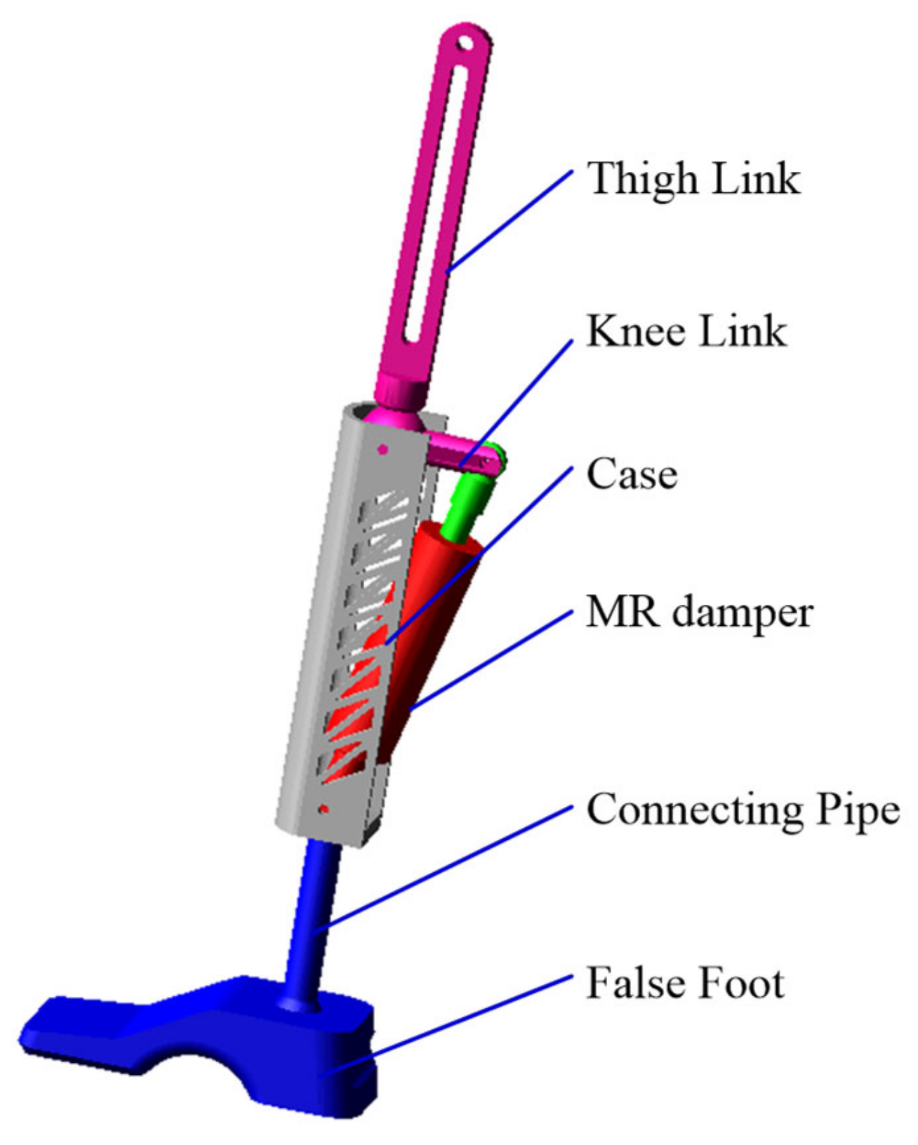
2.1. Working Principle of MR Prosthetic Knee Joint

Figure 3 shows the three-dimensional model of MR prosthesis, and Figure 4 shows the structural principle of MR prosthesis. The MR prosthesis is mainly composed of thigh link, MR prosthetic knee joint, connecting tube and a prosthetic foot, among which the MR prosthetic knee joint consists of a two-link mechanism and a MR damper. The two-link mechanism includes a knee joint link and a shell. The knee joint link is connected to the thigh link; the shell part is connected to the prosthetic foot through a connecting tube, and the knee joint link and the shell are connected through hinge C. The lifting lugs at both ends of the MR damper are respectively connected to the knee joint connecting rod and the shell through hinges B and D. The key structural parameters of MR prostheses are shown in Table 3.
It can be seen from Figure 4 that the length of the MR damper can be expressed as:
l MRD 2 = l CD 2 + l CB 2 2 l CD l CB cos ( θ 1 θ 2 )
where lCD is the length from hinge C to hinge D, and lCB is the length from hinge C to hinge B, whose values are 240 mm and 45 mm, respectively.
Substituting Equations (1)–(3), the length of the MR damper is obtained and shown in Figure 5. It can be seen that the length of the MR damper reaches the maximum and minimum values at the gait cycle 72% and 100% respectively, which are 227 mm and 193.7 mm. Therefore, the stroke of the proposed MR damper should be greater than 33.3 mm.

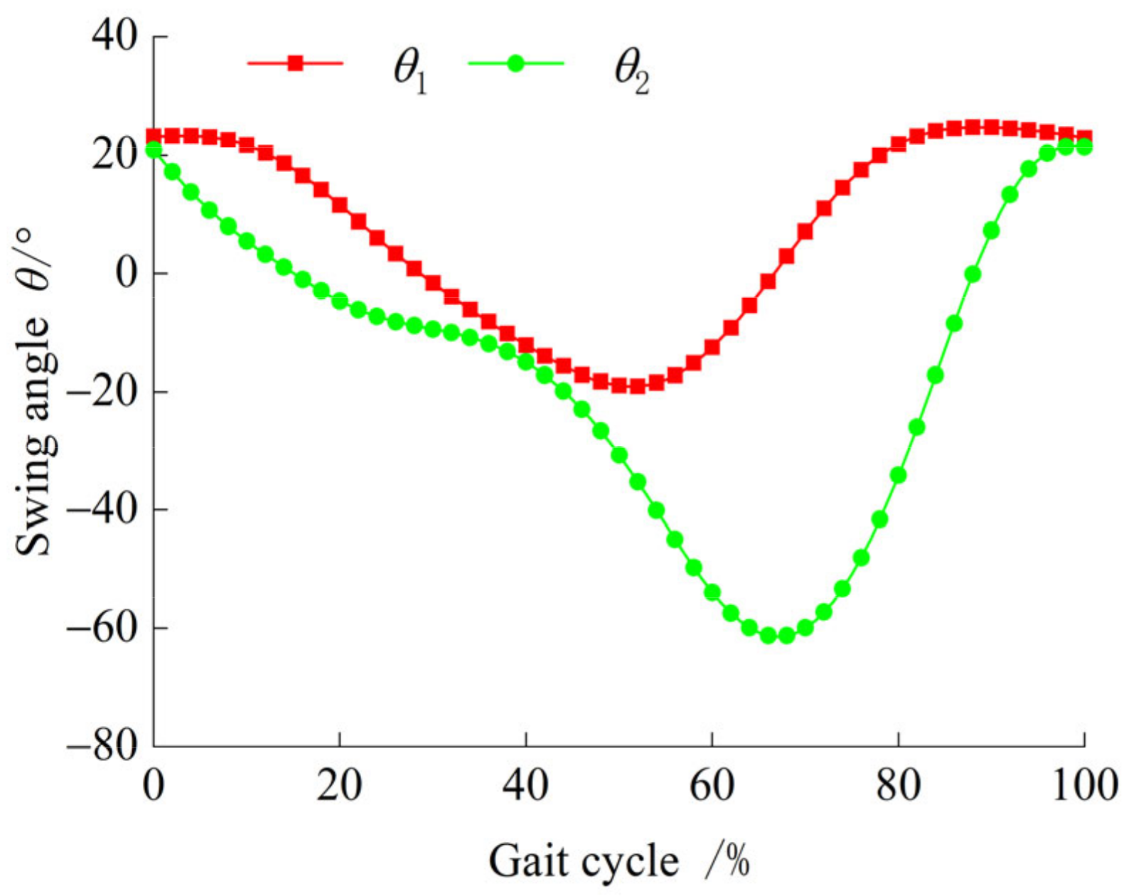
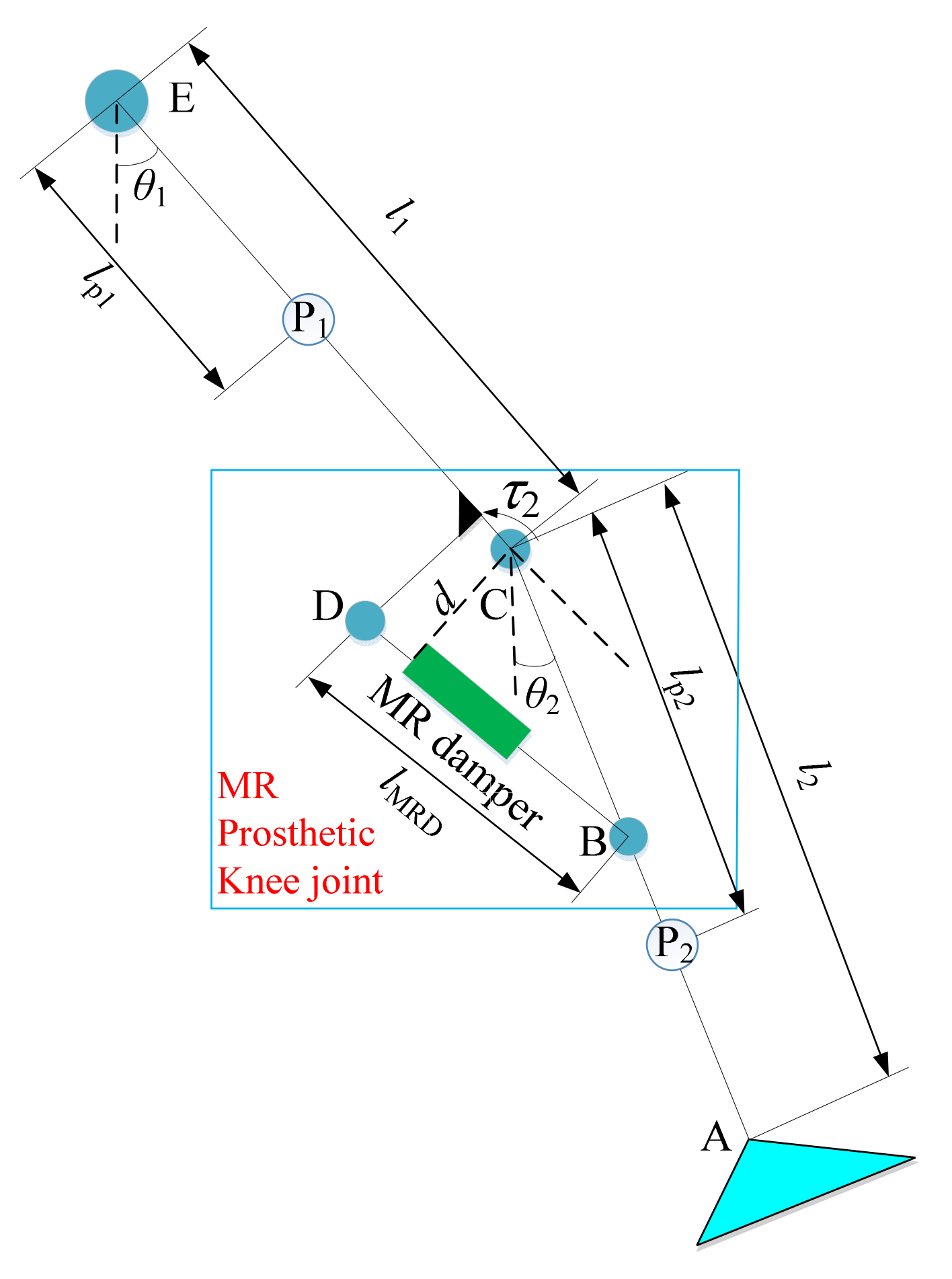
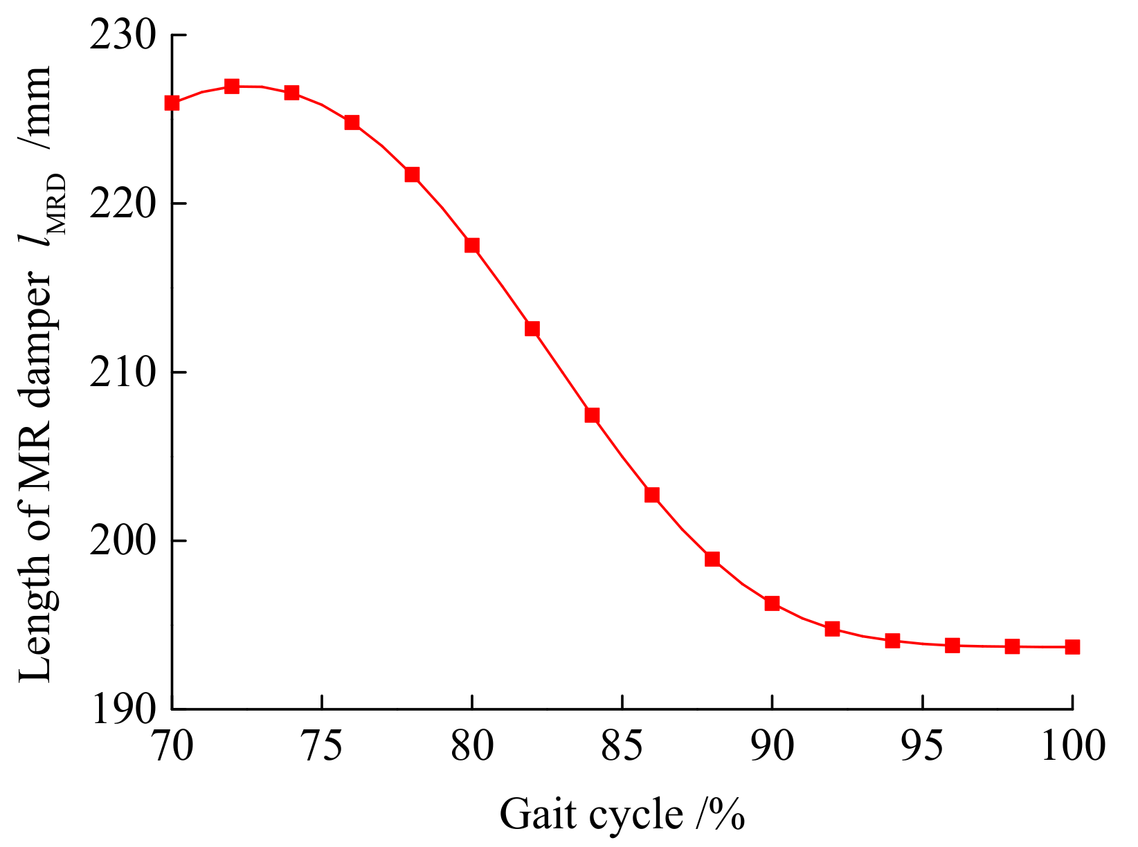
2.2. Kinetic Modeling of MR Prosthetic Knee Joint

To realize the controllable damping force of the MR prosthetic knee joint and reasonably design the MR damper structure, it is necessary to determine the required damping force of the MR prosthetic knee joint. Since the control object of the MR prosthetic is the knee joint, the main research is to control the knee joint in the swing phase. According to the Lagrangian equation, the kinetic equation of the MR prosthetic knee joint in the swing phase can be expressed as:
τ 1 τ 2 = M 11 θ ¨ 1 + M 12 θ ¨ 2 + C 1 + G 1 τ 2 = M 21 θ ¨ 1 + M 22 θ ¨ 2 + C 2 + G 2
where τ1 and τ2 are the moments applied to hinge E and hinge C, respectively; θ1 and θ2 are the angles between EC, CA and the vertical direction respectively; M11, M12, M21 and M22 are the moments of inertia matrix components respectively; C1 and C2 represent the centripetal force and Coriolis force of EC and CA respectively; G1 and G2 express the gravity of EC and CA, respectively.
The moment of inertia matrix components M11, M12, M21 and M22 can be expressed as:
M 11 = I 1 + m 1 l p 1 2 + m 2 l p 2 2
M 12 = M 2 1 = I 1 + m 1 l p 1 2 + m 2 l p 2 2
M 22 = I 2 + m 2 l p 2 2
where I1 and I2 are the moments of inertia of EC and CA, respectively; m1 and m2 are their masses, respectively; lp1 and lp2 are the lengths to their center of mass, respectively.
Coriolis force C2 can be expressed as:
C 2 = m 2 l 1 l p 2 sin ( θ 1 θ 2 ) θ ˙ 1
where l1 is the length of EC.
The gravity G2 can be expressed as:
G 2 = m 2 l p 2 g sin θ 2
The control torque τ2 of MR damper acting on hinge C is:
τ 2 = F d
where F is the output damping force of the MR damper; d is the distance from hinge C to BD, which can be expressed as:
d = l 1 l 2 sin ( θ 1 θ 2 ) / l MRD
where l2 is the AC length, and lMRD is the BD length.
Substituting Equations (5)–(11) into (4), it can be deduced as:
F d = M 21 θ ¨ 1 + M 22 θ ¨ 2 + C 2 + G 2
It can be seen that the MR prosthetic knee joint is a highly nonlinear system. Non-linear terms such as moment arm d, Coriolis force C2 and self-weight G2 will affect the knee angle control of the MR prosthetic knee joint.

3. Design of MR Damper Used in the MR Prosthetic Knee Joint

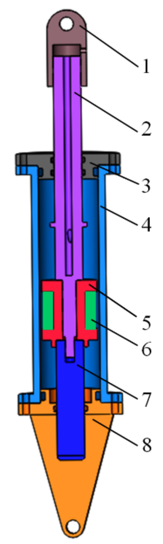
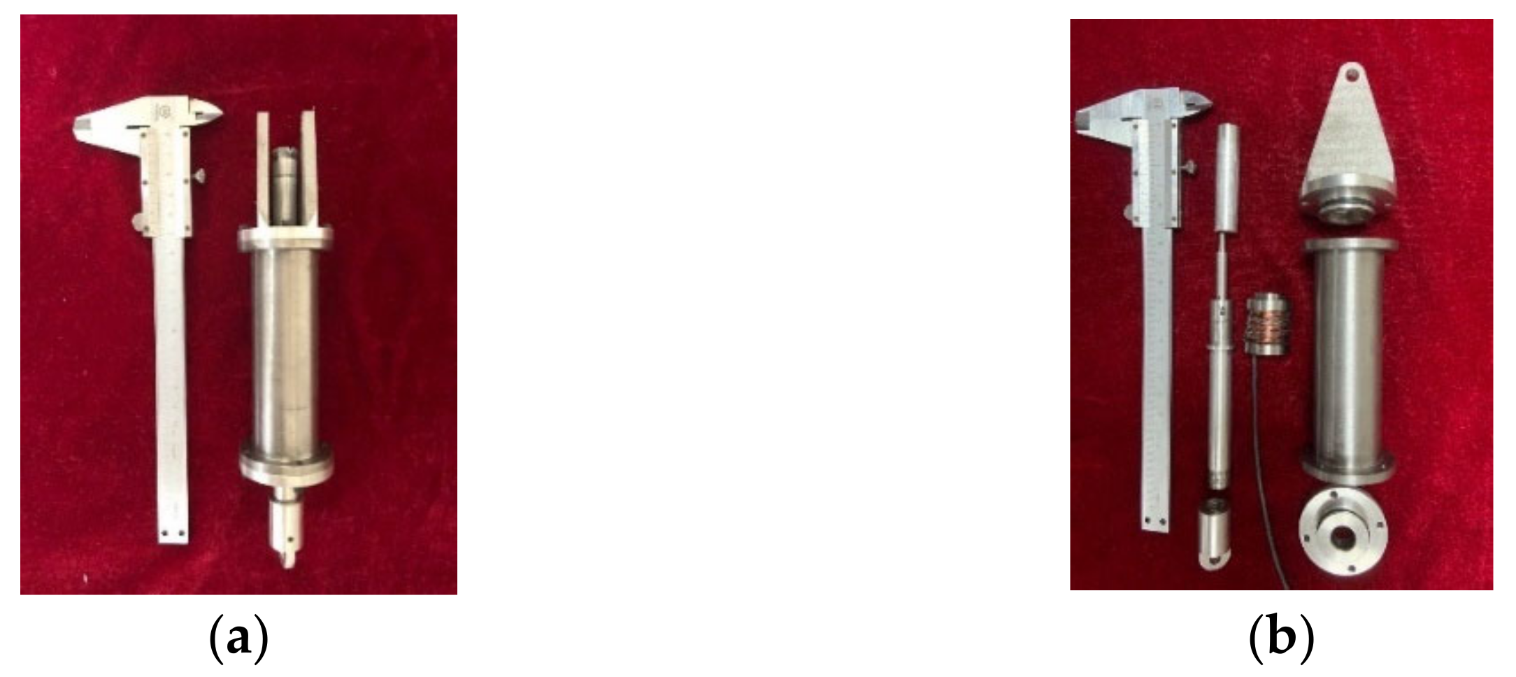
3.1. Structure Principle of the Proposed MR Damper

According to the working principle of the MR damper, the designed MR damper is shown in Figure 6. As can be seen from the figure, the MR damper is mainly composed of lifting lugs, piston rods A and B, an end cover, a cylinder, a coil winding frame and an excitation coil. Among them, piston rods A and B are connected to each other through threads and play the role of fixing the coil winding frame. The excitation coil is evenly wound on the coil winding frame; both of them form a piston head, and there is an annular gap between the piston head and the MR damper cylinder. The MR fluid flows into the cylinder of the MR damper to make the gap between the piston head and the cylinder form an effective damping channel. The piston rod moves up and down due to external vibration, so that the MR fluid in the upper and lower chambers flows back and forth at the effective damping gap. The excitation coil is powered on, and a variable magnetic field is generated. The rheological characteristics of the MR fluid change under the action of the magnetic field. The viscosity of the MR fluid increases as the increase of current, that is, the pressure difference between the two ends of the effective damping gap, increases. Therefore, within a certain range, the output damping force of the MR damper can be adjusted by controlling the applied current of the excitation coil.

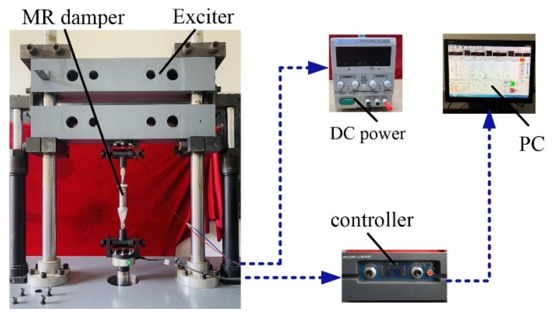
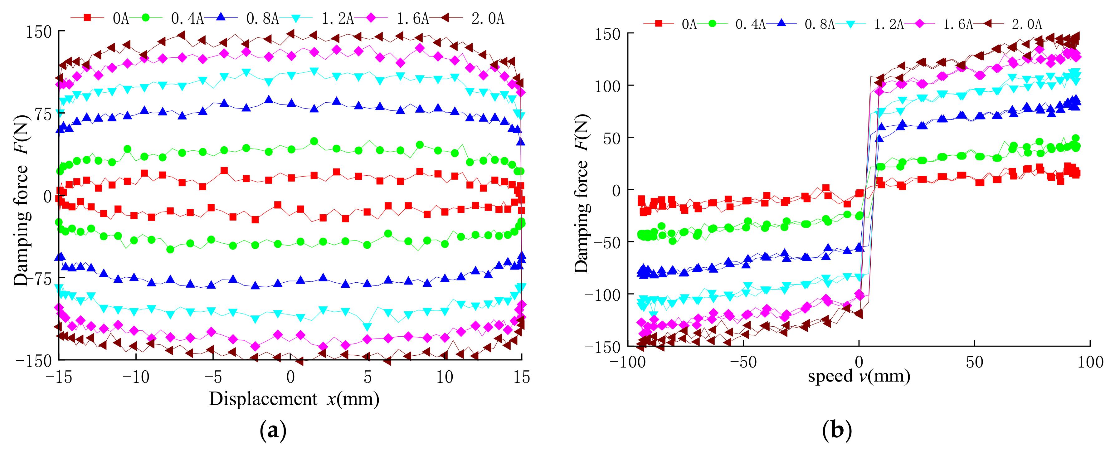
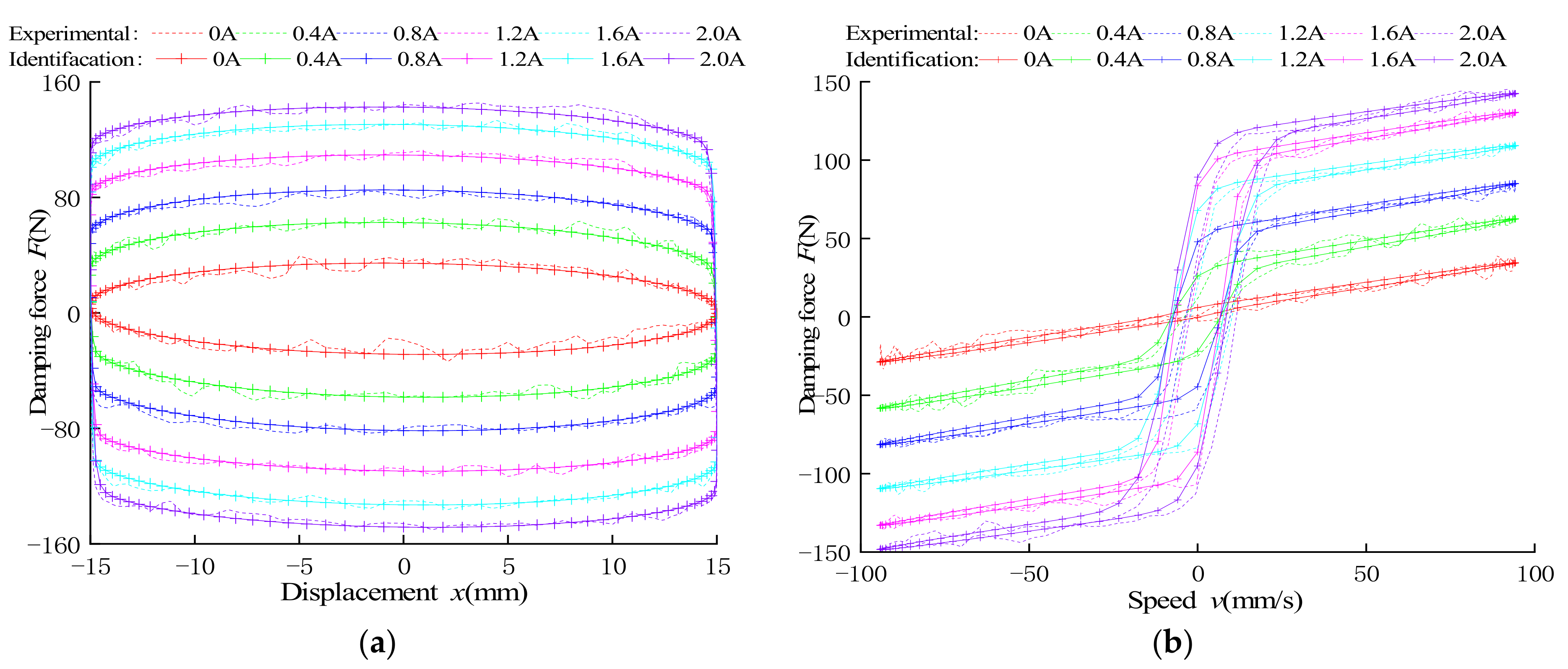
3.2. Dynamic Performance Tests of the Proposed MR Damper

Figure 7 shows the prototype of the developed MR damper. To test the dynamic characteristics of the proposed MR damper, a test system is set up as shown in Figure 8. The test system is generally composed of a fatigue stretching machine, MR damper, DC power supply, electro-hydraulic loading controller and PC. The fatigue stretching machine provides different types of excitation for the MR damper. The DC power supply offers different current signals for the excitation coil. The electro-hydraulic loading controller is used to adjust the working state of the stretching machine and to adjust the damping force and displacement on the fatigue stretching machine. The signal is transmitted to the data acquisition interface of the PC.
Figure 9 shows the dynamic performance of the MR damper under different currents at an amplitude of 15 mm and a frequency of 1 Hz. Observing Figure 9a, it can be seen that the damping force increases with the increase of the applied current. The output damping force is 22.4 n at zero current, and the output damping force reaches 147.7 n at a current of 2 A. Observing Figure 9b, when the current is fixed, the damping force increases slightly with the increase of velocity. When the speed is fixed, the damping force increases significantly with the increase of current, but when the current exceeds 1.6 A, the increasing trend of damping force gradually slows down; the reason is that the magnetic circuit of the MR damper tends to saturate with the increase of current.

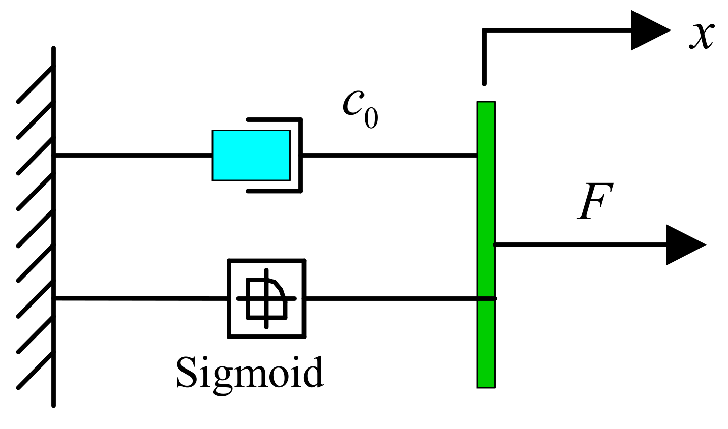
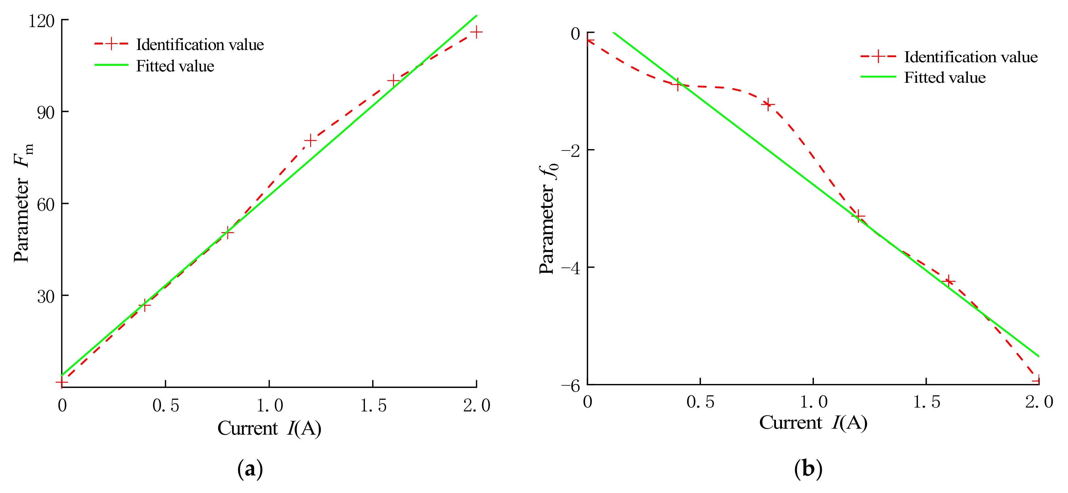
3.3. Establishment of Forward Mechanics Model of the MR Damper

The Bingham model can effectively reflect the relationship between the output damping force and the structural parameters, but the accuracy of the model is not high when the damper works in low speed. To accurately reflect the mechanical properties of the MR damper, the adjustable sigmoid model shown in Figure 10 is used to establish a positive mechanical model of the MR damper. The adjustable sigmoid model is formed by the parallel combination of the sigmoid function and the viscous damping element, which is expressed as:
F = F m 1 e a ( x ˙ + k x ) 1 + e a ( x ˙ + k x ) + C 0 ( x ˙ + k x ) + f 0
where Fm is the maximum yield force, which affects the length of the hysteresis loop; a is the parameter related to the damping coefficient of the pre-yield zone; k is the scale factor of the hysteresis loop width; C0 is the viscous damping coefficient, and f0 is the bias damping force.
Since the applied current has a great influence on the output damping force, the parameters of the damping force data under different currents are identified. Based on the least square method, the relationship between parameters and the currents is acquired. The parameter identification results are shown in Table 4. It can be seen that the parameters a, k and C0 do not change significantly with the current, but the parameters Fm and f0 are greatly affected by the current. Therefore, the average value of the identified a, k, and C0 is used to replace the parameters in the model, that is, the values of a, k, and C0 are 0.32, −0.47 and 0.33, respectively.
The polynomial fitting method was adopted to fit the relationship between the parameters Fm, f0 and the current, and the results are shown in Figure 11. It can be seen that the parameter Fm increases with increase of the current, while the parameter f0 decreases with increases of the current. The relationship between parameters Fm, f0 and current can be expressed as follows:
F m = b 1 I + c 1
f 0 = b 2 I + c 2
where b1, c1, b2 and c2 are fitting parameters.
According to the results of parameter identification, an adjustable sigmoid model is established and compared with the experimental data, the result is shown in Figure 12. It can be seen that the established adjustable sigmoid model can better reflect the characteristics of damping force with displacement and damping force with velocity. Compared with the Bingham model based on structural parameters, the adjustable sigmoid model can better reflect the damping characteristics of the MR damper at low speeds.

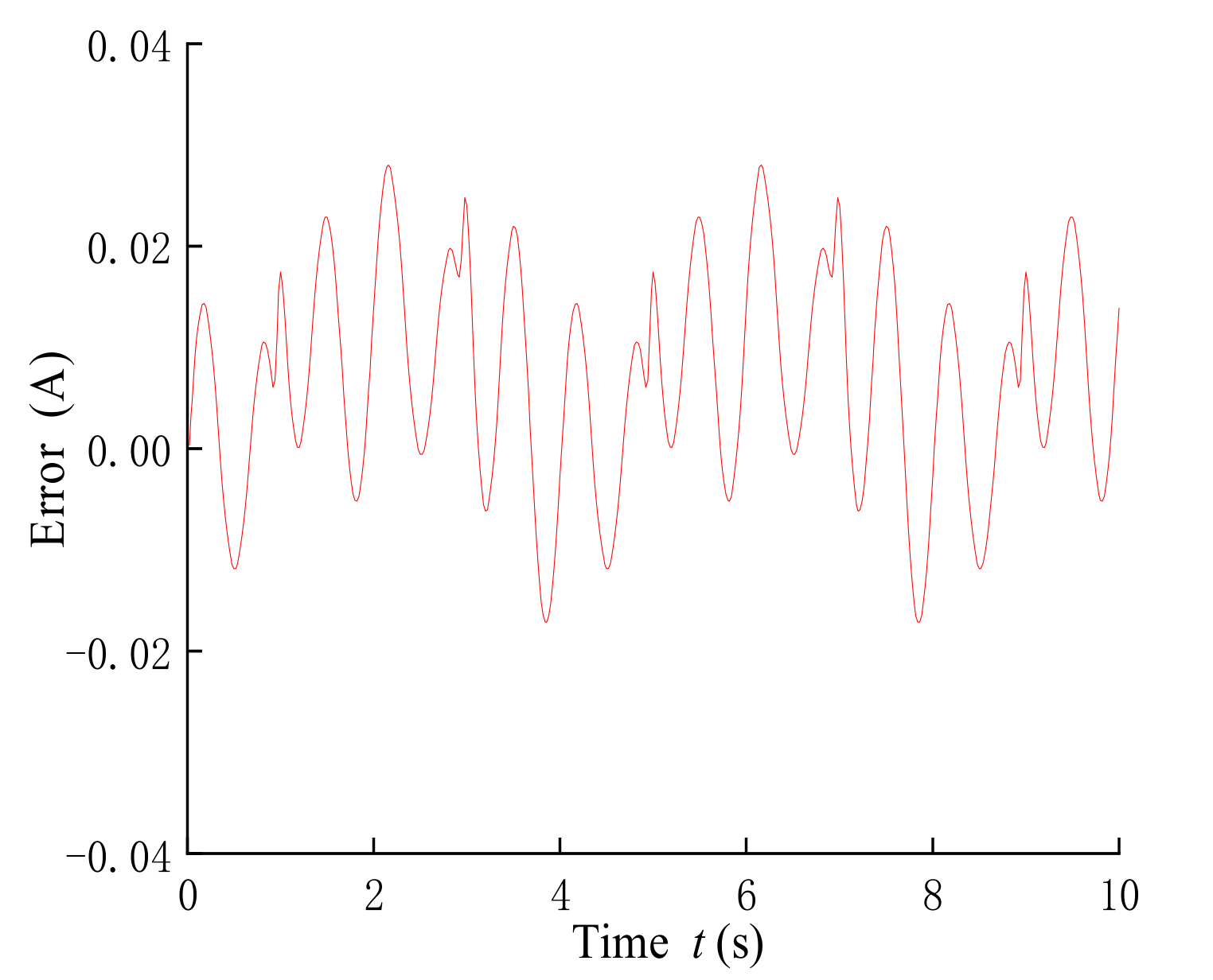
3.4. Establishment of Reverse Mechanics Model of the MR Damper

In order to make the MR damper accurately output the expected damping force, a reverse mechanical model of the MR damper is needed. Since the relationship between the current and the damping force cannot be directly inverted and since the BP neural network can realize the approximation of any nonlinear mapping relationship and has a strong generalization ability, the BP neural network is used to establish the inverse mechanical model of the MR damper.
Due to the limited experimental data, the established adjustable sigmoid model data is used as the training and verification samples of the BP neural network. Training samples are obtained by changing the piston rod displacement, piston rod speed and output damping force in the adjustable sigmoid model. The sample data is randomized, and the BP neural network is initialized for training, and finally, the data is normalized.
The established BP neural network is trained and verified by setting the training number to 100 times. The result is shown in Figure 13. It can be seen that the fitted value of the BP neural network is close to the sample value, showing a sinusoidal distribution. Figure 14 shows the error curve between the sample value and the fitted value, and the maximum training error of the BP neural network is only 0.026.

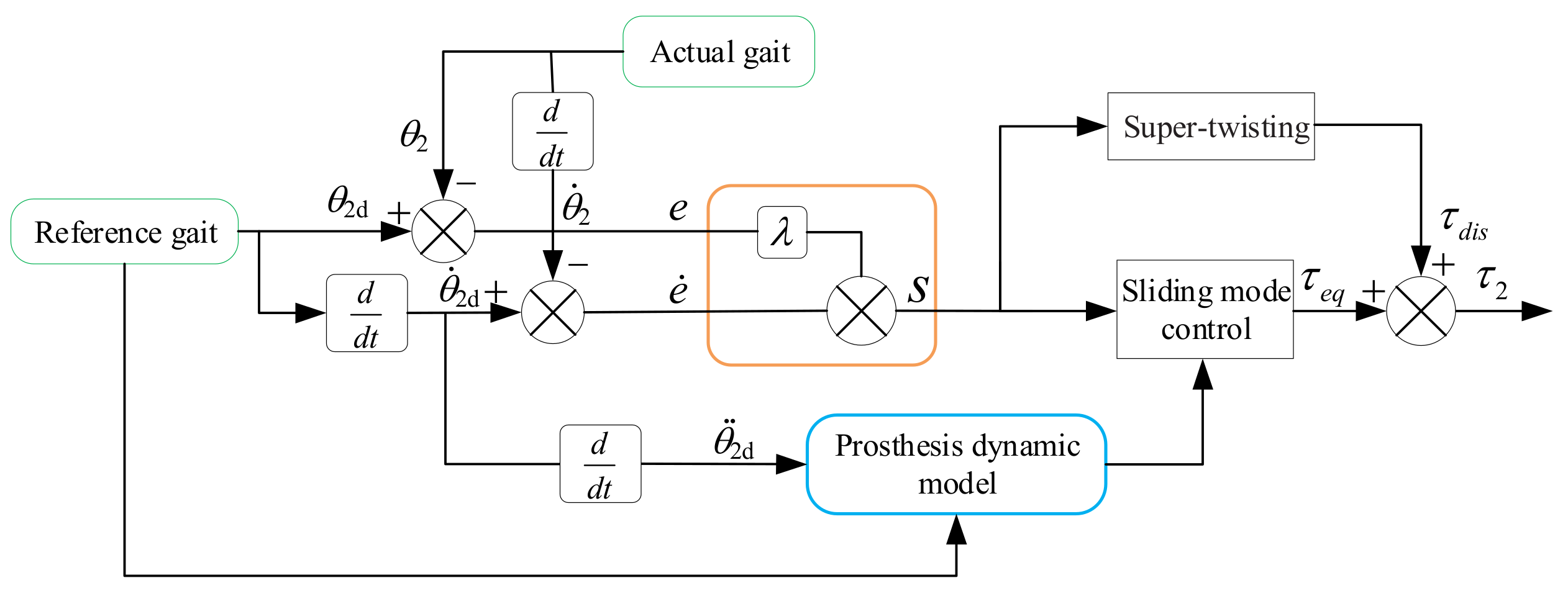
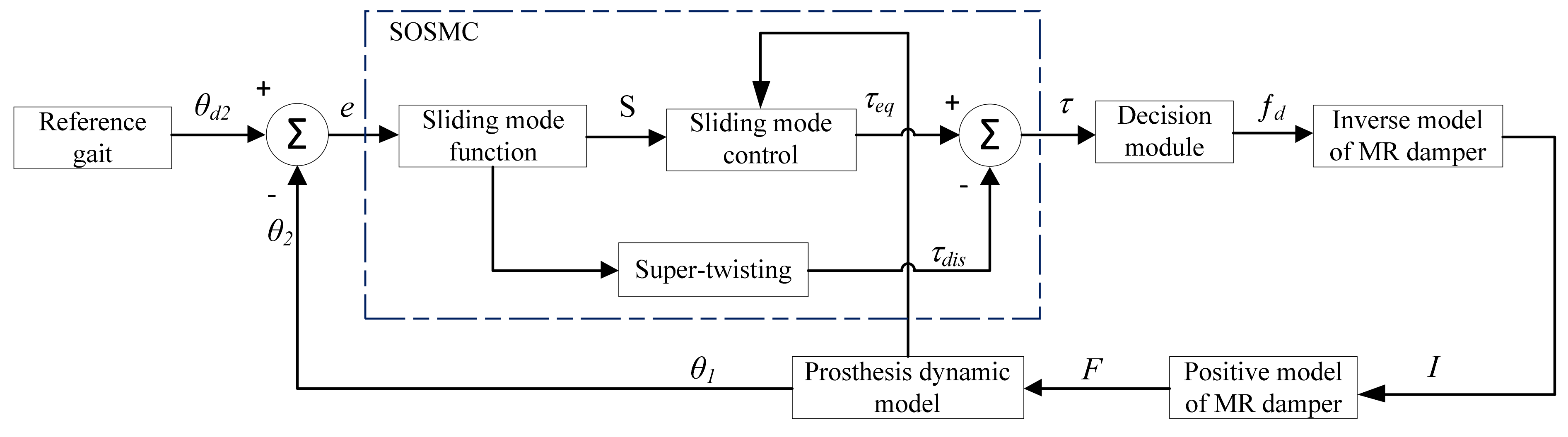
4. Trajectory Tracking Control Based on Second-Order Sliding Mode

Due to uncertainties and external interference, traditional PD control cannot track the knee joint swing trajectory well in the MR prosthesis control model. In addition, the first-order sliding mode control is to make the control system switch on the sliding mode surface, which easily causes the chattering phenomenon in the control system. Therefore, a second-order sliding mode control (SOSMC) algorithm is developed to control the swing trajectory of the actual MR prosthesis. The sliding mode surface of sliding mode control is constituted of the error and derivative of the current state quantity and the ideal state quantity of the system, and the phase plane is defined to make the state variables converge on the ideal state. The SOSMC algorithm can effectively eliminate the chattering phenomenon of the system by designing its sliding mode surface and switching rate. The principles of SOSMC are shown in Figure 15, which mainly includes equivalent continuous term and equivalent discrete term.
The proposed SOSMC can be expressed as:
τ 2 = τ e q + τ d i s
where τeq is the equivalent continuous term, and τdis is the equivalent discrete term.
The equivalent continuous term can be expressed as:
τ e q = M 21 θ ¨ 1 + M 22 ( ε sgn ( S ) + λ e ˙ + θ ¨ 2 d ) + C 2 + G 2
where S is the sliding mode surface function; λ is the parameter to be designed and θ ¨ 2 d is the second derivative of the reference gait.
The sliding mode surface function S is defined as:
S = λ e + e ˙
The equivalent discrete term is established by using super-twisting, which can be expressed as:
τ d i s = μ 1 0 t sign ( S ) d t + μ 2 | S | 0.5 sign ( S )
In the Equation (19), the positive real numbers μ1 and μ2 need to satisfy:
μ 2 > ϕ 0 K m 0
μ 1 2 4 ϕ 0 K m 2 μ 2 K M + ϕ 0 μ 2 m M + ϕ 0 > 0
where ϕ 0 ,   K m ,   and   K M are positive real numbers.
The Lyapunov function V is defined as:
V = | S | = S sign ( S )
Taking the derivative of V, it can be obtained as:
V ˙ = S ˙ sign ( S )
Substituting Equation (18) into Equation (23), the derivative of V is:
V ˙ = [ λ e ˙ + e ¨ ] sign ( S ) = λ θ ˙ 2 d θ ˙ 2 + θ ¨ 2 d θ ¨ 2 sign ( S )
In the formula, the second derivative of the calf swing angle θ ¨ 2 can be expressed as:
θ ¨ 2 = M 22 1 ( τ M 21 θ ¨ 1 C 2 G 2 )
Substituting Equation (25) into Equation (24), the following can be obtained:
V ˙ = λ θ ˙ 2 d λ θ ˙ 2 + θ ¨ 2 d M 22 1 ( τ M 21 θ ¨ 1 C 2 G 2 ) sign ( S )
Substituting Equations (16), (17) and (19) into Equation (26), we have:
V ˙ = sign ( S ) ( λ θ ˙ 2 d λ θ ˙ 2 + θ ¨ 2 d M 22 1 ( M 21 θ ¨ 1 + M 22 ( ε sign ( S ) + λ e ˙ + θ ¨ 2 d ) + M 21 θ ¨ 1 + C 2 + G 2 + μ 1 I 0 t sign ( S ) d t + μ 2 I | S | 0.5 sign ( S ) M 21 θ ¨ 1 C 2 G 2 ) )
Since μ1 and μ2 are positive real numbers, and t 0 , it can be deduced that:
V ˙ = M 22 μ 1 t + μ 2 | S | 0.5 0
Because V 0   and   V ˙ 0 , So the MR prosthesis system is gradually stable.
Figure 16 shows the principle of the MR prosthesis based on SOSMC, which mainly includes SOSMC, the inverse model and the positive model of MR damper and the dynamic model of the MR prosthesis. The sliding mode control in SOSMC is established based on the sliding mode function and the dynamic model of the prosthesis, while the super-twisting algorithm is established based on the sliding mode function. The sliding mode function is established based on the difference between the reference swing angle of the lower leg and the actual swing angle.

5. Analysis of Trajectory Tracking Control of MR Prosthesis Knee Joint

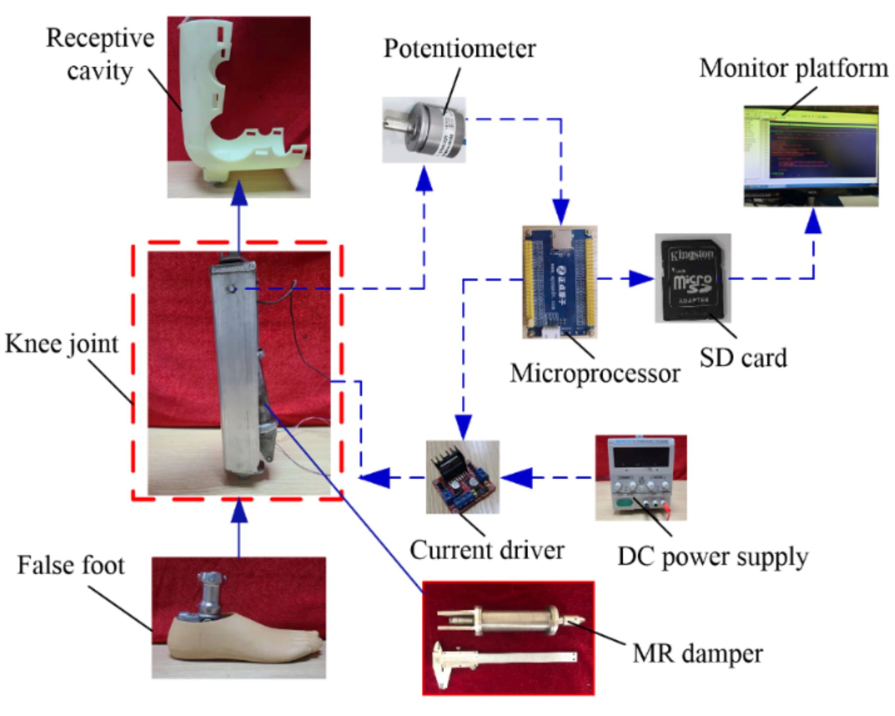
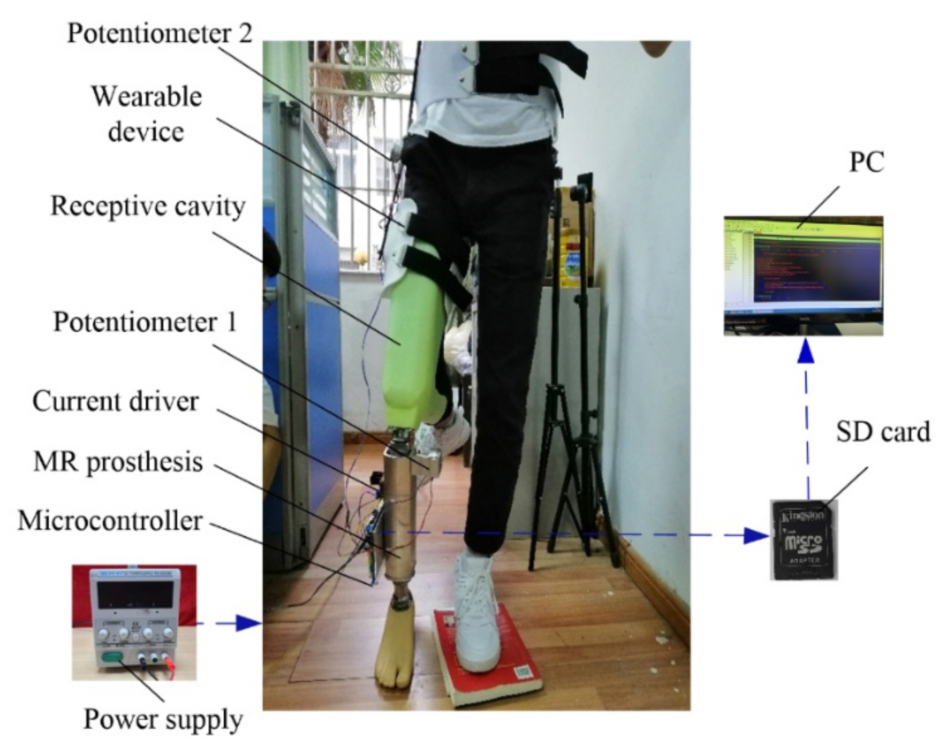
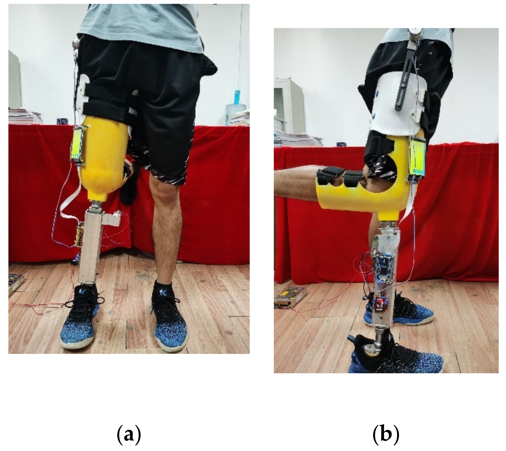
5.1. Test System Setup

In order to test the designed MR prosthesis, the thigh receiving cavity is processed by 3D printing technology according to the relevant parameters of the thigh of the experimenter. The receiving cavity material is processed by the photosensitive resin, which can ensure that the receiving cavity has a certain strength and toughness so that it is convenient to fix with the MR prosthesis and the leg of the experimenter. In addition, the upper link and the lower link are made of aluminum alloy, which effectively reduces the weight of the MR prosthesis. The connecting tube is made of stainless steel, and its length can be adjusted according to the height of the experimenter, so as to ensure that the experimenter can stand normally and swing the legs. The prosthetic footboard is made of silicone material and rigidly connected with the connecting tube. Since the focus is on the trajectory tracking of the knee joint, the degree of freedom at the ankle joint is ignored.
The MR prosthesis control system and its prosthetic test system are shown in Figure 17 and Figure 18, respectively, mainly including MR prostheses, microcontrollers, potential sensors, a data acquisition system and corresponding wearable devices. The control system is based on a single-chip microcomputer and consists of a signal conditioning module, a decision module, a controller module, a reverse model and a positive model of the MR damper. The working diagram of the MR prosthesis is shown in Figure 19, wherein the piezoelectric potentiometer converts the electrical signal during the swinging process of the prosthesis into an angle signal. The DC power supply supplies power to the microcontroller and the MR damper; the control torque signal generated by the microcontroller is converted into a current signal through the decision module, and the signal is controlled by the current driver to control the current of the MR damper. The data acquisition card is used to collect the angle signal detected by the potential sensor and import it into the PC. In addition, the monitor platform in the PC is used to adjust the relevant parameters of the designed controller offline, so that the MR prosthesis can better track the reference gait.

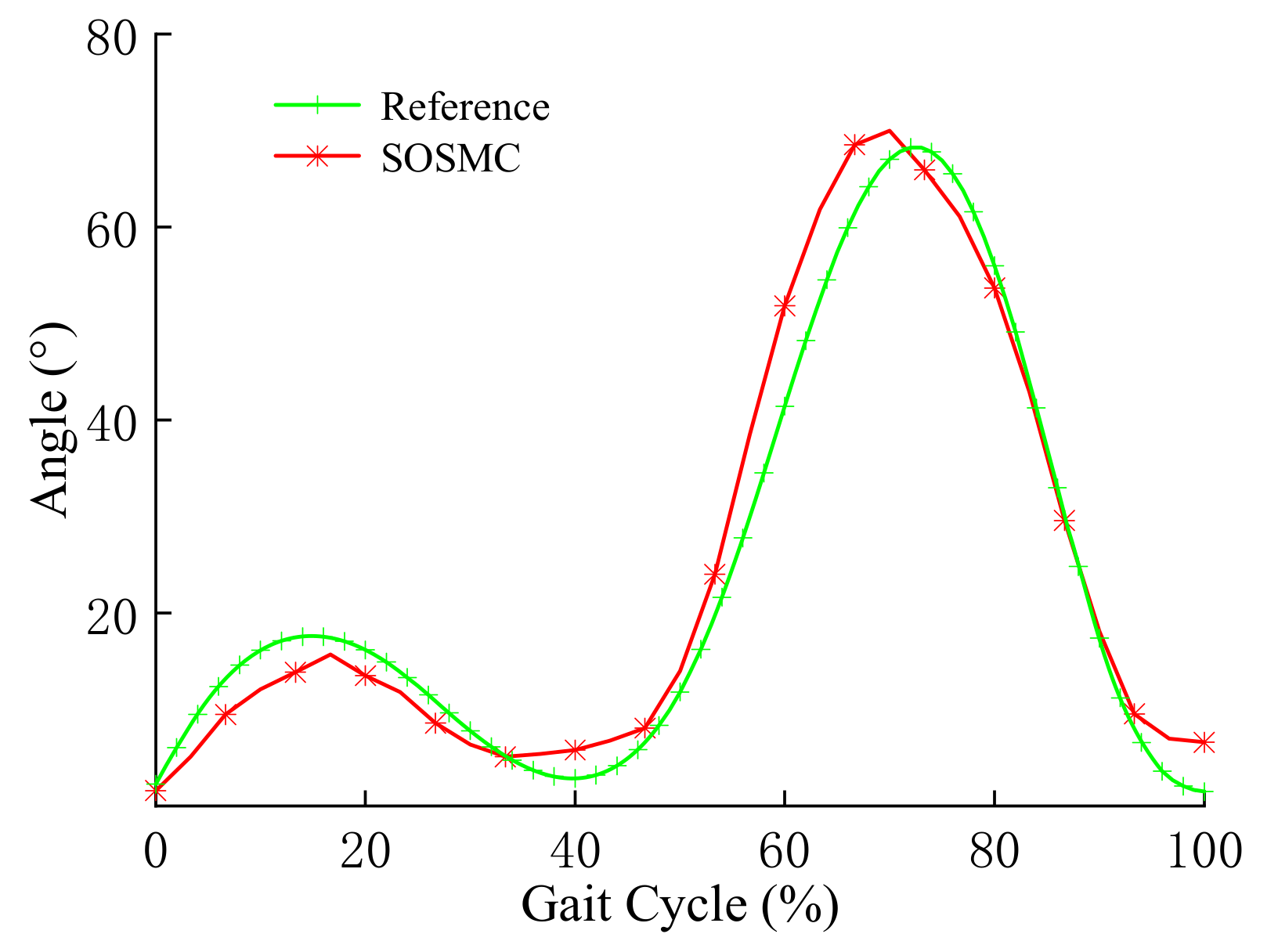
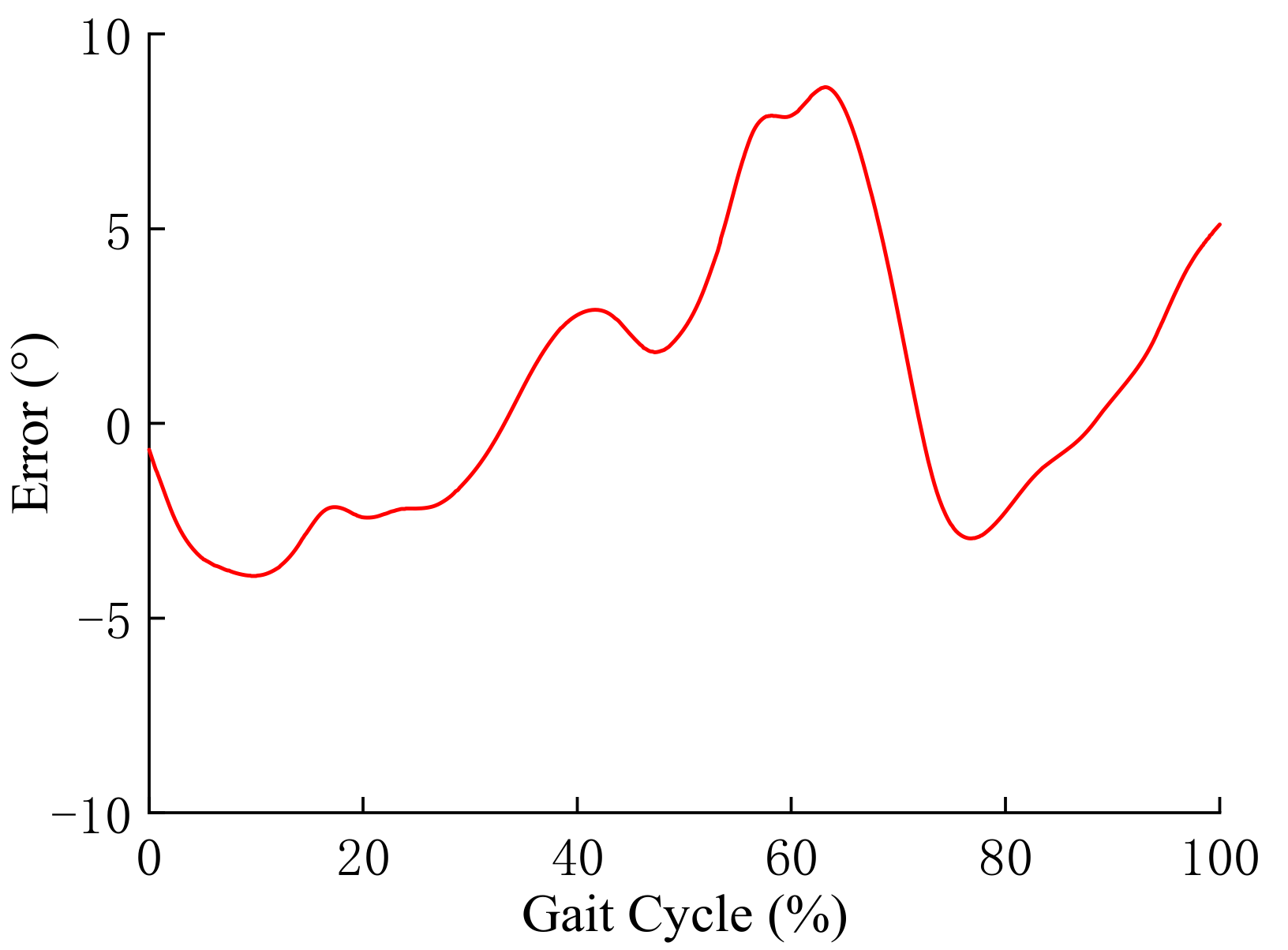
5.2. Analysis of Trajectory Tracking Control

The swing trajectory of the MR prosthetic knee joint based on SOSMC is shown in Figure 20. It can be seen that the MR prosthesis can better track the motion trajectory of the knee joint, but there are relatively obvious errors around the gait cycle of 15–18% and 68–72%. In the gait period of 76–94%, the knee joint swing trajectory can almost achieve the unbiased tracking of the knee joint reference trajectory, but when the gait period is 100%, the knee joint swing angle has a lower error than the reference swing angle. The reason is may be that the MR prosthesis is in contact with the ground at this moment, and impacts on the ground affect gait quality.
Figure 21 displays the swing trajectory error of the MR prosthetic knee joint based on SOSMC. It can be seen that the initial error of the knee joint swing trajectory is about 1.6°. When the gait period is about 62%, the positive error of the swing angle reaches the maximum of 9.4°; when the gait period is about 14%, the negative error of the knee joint reaches the maximum of −4.7°. The error between the knee joint swing trajectory and the reference swing trajectory is −3.8° at the gait cycle of 77%. The main reason is that the range of damping force of the MR damper is limited, which means the control torque of SOSMC cannot reach the expected value.

6. Conclusions

In this work, a new MR prosthetic knee joint using an MR damper as the brake is designed, and a dynamic model is established according to the gait data of healthy people walking on flat ground. To investigate the performance of the MR prosthesis knee joint, an MR damper is designed, and its dynamic performance is also tested. A forward mechanical model of the MR damper based on the adjustable sigmoid model is deduced, and an inverse mechanical model of the MR damper is also proposed using BP neural network.
The SOSMC algorithm is developed considering the uncertainty of the MR prosthesis model and the existence of external interference, and an MR prosthesis knee joint experimental test system is set up. The experimental test results show that the maximum positive error of the knee joint swing trajectory based on SOSMC is 9.4°, which effectively proves that the MR prosthesis tracks the reference swing trajectory well.
However, a mature prosthesis must consider the impact of various realistic terrain and environmental conditions. Meanwhile, it must be tested for different use scenarios to realize commercialization and marketization. In the next work, further verification of the reliability of the prosthesis on conventional roads will be carried out.

Author Contributions

Q.Z. developed the MR damper and edited the paper; J.Z. conducted experimental research and wrote the first draft; X.M. supported the experimental process; F.Y. carried out theoretical analysis; G.H. contributed the experimental research of the prosthetic knee joint and revised the paper. All authors have read and agreed to the published version of the manuscript.

Funding

This research was funded by the National Natural Science Foundation of China (No. 52165004), Key Projects of Hangzhou Agricultural and Social Development Research Program (No. 20212013 B04) and Zhejiang Province Basic Public Welfare Research Project (No. LGG20 E050007).

Institutional Review Board Statement

Not applicable.

Informed Consent Statement

Not applicable.

Data Availability Statement

Not applicable.

Conflicts of Interest

The authors declare no conflict of interest.

References

  1. Segal, A.D.; Orendurff, M.S.; Klute, G.K.; Mcdowell, M.L.; Pecoraro, J.; Czerniecki, J.M. Kinematic and kinetic comparisons of transfemoral amputee gait using C-Leg and Mauch SNS prosthetic knees. J. Rehabil. Res. Dev. 2006, 43, 857–869. [Google Scholar] [CrossRef] [PubMed]
  2. Price, M.A.; Beckerle, P.; Sup, F.C. Design optimization in lower limb prostheses: A review. IEEE Trans. Neural Syst. Rehabilit 2019, 27, 1574–1588. [Google Scholar] [CrossRef] [PubMed]
  3. Pi, M.; Li, Z.; Li, Q.; Kan, Z.; Xu, C.; Kang, Y.; Su, C.; Yang, C. Biologically inspired deadbeat control of robotic leg prostheses. IEEE-ASME Trans. Mechatron. 2020, 25, 2733–2742. [Google Scholar] [CrossRef]
  4. Varol, H.A.; Goldfarb, M. Decomposition-based control for a powered knee and ankle transfemoral prosthesis. In Proceedings of the IEEE 10th International Conference on Rehabilitation Robotics, Noordwijk, The Netherlands, 13–15 June 2007; pp. 783–789. [Google Scholar]
  5. Pauw, K.D.; Serrien, B.; Baeyens, J.P.; Cherelle, P.; Meeusen, R. Prosthetic gait of unilateral lower-limb amputees with current and novel prostheses: A pilot study. Clin. Biomech. 2020, 71, 59–67. [Google Scholar] [CrossRef] [PubMed]
  6. Cho, J.; Kong, K. Mechanism design of a robotic leg for running considering radial force producibility and tangential mobility. Int. J. Control Autom. 2020, 34, 34–42. [Google Scholar] [CrossRef]
  7. Convens, B.; Dong, D.; Furnemont, R.; Verstraten, T.; Vanderborght, B. Modeling, design and test-bench validation of a semi-active propulsive ankle prosthesis with a clutched series elastic actuator. IEEE Robot. Autom. Lett. 2019, 4, 1823–1830. [Google Scholar] [CrossRef]
  8. Hu, G.; Zhang, J.; Zhong, F.; Yu, L. Performance evaluation of an improved radial magnetorheological valve and its application in the valve controlled cylinder system. Smart Mater. Struct. 2019, 28, 047003. [Google Scholar] [CrossRef]
  9. Ruan, X.; Xuan, S.; Zhao, J.; Bian, H.; Gong, X. Mechanical performance of a novel magnetorheological fluid damper based on squeeze-valve bi-mode of MRF. Smart Mater. Struct. 2020, 29, 55018. [Google Scholar] [CrossRef]
  10. Arteaga, O.; Terán, H.C.; Morales, H. Design of Human Knee Smart Prosthesis with Active Torque Control. Int. J. Mech. Eng. Robot. Res. 2020, 9, 14–22. [Google Scholar] [CrossRef]
  11. Ochoa-Diaz, C.; Rocha, T.S.; Oliveira, L.D.L.; Paredes, M.G.; Borges, G.A. An above-knee prosthesis with magnetorheological variable-damping. In Proceedings of the 5th IEEE RAS/EMBS International Conference on Biomedical Robotics and Biomechatronics, IEEE, Sao Paulo, Brazil, 12–15 August 2014; pp. 108–113. [Google Scholar]
  12. Xu, L.; Wang, D.H.; Fu, Q.; Yuan, G.; Bai, X.X. A novel motion platform system for testing prosthetic knees. Measurement 2019, 51, 139–151. [Google Scholar] [CrossRef]
  13. Xie, H.L.; Liang, Z.; Li, F.; Guo, L.X. The knee joint design and control of above-knee intelligent bionic leg based on magnetorheological damper. Int. J. Autom. Comput. 2010, 7, 277–282. [Google Scholar] [CrossRef]
  14. Bulea, T.C.; Kobetic, R.; To, C.S.; Audu, M.L.; Schnellenberger, J.R.; Triolo, R.J. A Variable Impedance Knee Mechanism for Controlled Stance Flexion During Pathological Gait. IEEE-ASME Trans. Mechatron. 2012, 17, 822–832. [Google Scholar] [CrossRef]
  15. Herr, H.M.; Wilkenfeld, A.; Bleck, O. Speed-Adaptive and Patient-Adaptive Prosthetic Knee. U.S. Patent 6,610,101, 26 August 2003. [Google Scholar]
  16. Nandi, G.C.; Ijspeert, A.J.; Chakraborty, P.; Nandi, A. Development of adaptive modular active leg (AMAL) using bipedal robotics technology. Robot. Auton. Syst. 2009, 57, 603–616. [Google Scholar] [CrossRef]
  17. Park, J.; Yoon, G.H.; Kang, J.W.; Choi, S.B. Design and control of a prosthetic leg for above-knee amputees operated in semi-active and active modes. Smart Mater. Struct. 2016, 25, 085009. [Google Scholar] [CrossRef]
  18. Cong, D.; Xu, X. Swing phase control of magnetorheological fluid intelligent artificial leg. J. Syst. Simul. 2006, 18, 916–922. [Google Scholar]
  19. Kim, J.H.; Oh, J.H. Development of an above knee prosthesis using MRD and leg simulator. In Proceedings of the 2001 IEEE International Conference on Robotics and Automation, Seoul, Korea, 1 February 2001; pp. 3686–3691. [Google Scholar]
  20. Fu, Q.; Wang, D.H.; Xu, L.; Gang, Y. A magnetorheological damper-based prosthetic knee and sliding mode tracking control method for an MRPK-based lower limb prosthesis. Smart Mater. Struct. 2017, 26, 045030. [Google Scholar] [CrossRef]
  21. Scandaroli, G.; Borges, G.; Rocha, D.A.; Nascimento, D.O. Adaptive Knee Joint Control for an Active Amputee Prosthesis. In Proceedings of the 2008 IEEE Latin American Robotic Symposium, Salvador, Brazil, 29–30 October 2008; pp. 164–169. [Google Scholar]
  22. Peng, F.; Wen, H.; Zhang, C.; Xu, B. Adaptive robust force position control for flexible active prosthetic knee using gait trajectory. Appl. Sci. 2020, 10, 2755. [Google Scholar] [CrossRef]
  23. Huang, H.; Zhang, F.; Hargrove, L.J.; Dou, Z.; Rogers, D.R.; Englehart, K.B. Continuous locomotion-mode identification for prosthetic legs based on neuromuscular-mechanical fusion. IEEE Trans. Bio-Med. Eng. 2011, 58, 2867–2875. [Google Scholar] [CrossRef] [PubMed] [Green Version]
  24. Huang, H.; Kuiken, T.A.; Lipschutz, R.D. A strategy for identifying locomotion modes using surface electromyography. IEEE Trans. Bio-Med. Eng. 2009, 56, 65–73. [Google Scholar] [CrossRef] [PubMed] [Green Version]
  25. Stinus, H. Biomechanics and evaluation of the microprocessor-controlled c-leg exoprosthesis knee joint. Z. Orthopädie Ihre. Grenzgeb. 2000, 138, 278–282. [Google Scholar] [CrossRef] [PubMed]
Figure 1. Swing trajectory of hip and knee joints.
Applsci 11 08305 g001
Figure 2. Swing angle of thigh angle θ1 and calf angle θ2.
Applsci 11 08305 g002
Figure 3. Three-dimensional model of MR prosthesis.
Applsci 11 08305 g003
Figure 4. Structural principle of MR prosthesis.
Applsci 11 08305 g004
Figure 5. Length of the MR damper.
Applsci 11 08305 g005
Figure 6. Schematic diagram of MR damper. (1) Upper lifting lug, (2) piston rod A, (3) end cover, (4) cylinder body, (5) coil winding frame (6) excitation coil, (7) piston rod B, (8) lower lifting lug.
Applsci 11 08305 g006
Figure 7. Prototype of the proposed MR damper. (a) Parts, (b) assembly.
Applsci 11 08305 g007
Figure 8. Performance test system for the proposed MR damper.
Applsci 11 08305 g008
Figure 9. Dynamic performance of MR damper under different currents. (a) Damping force-displacement, (b) damping force-speed.
Applsci 11 08305 g009
Figure 10. Schematic diagram of adjustable sigmoid model.
Applsci 11 08305 g010
Figure 11. The relationship between the parameters Fm, f0 and the current: (a) parameter Fm, (b) parameter f0.
Applsci 11 08305 g011
Figure 12. Comparison of dynamic performance of proposed MR damper: (a) damping force-displacement, (b) damping force-speed.
Applsci 11 08305 g012
Figure 13. Fitting accuracy curve using BP neural network.
Applsci 11 08305 g013
Figure 14. Error curve between sample value and fitted value.
Applsci 11 08305 g014
Figure 15. SOSMC principle diagram.
Applsci 11 08305 g015
Figure 16. Principle of MR prosthesis based on SOSMC.
Applsci 11 08305 g016
Figure 17. MR prosthesis control system.
Applsci 11 08305 g017
Figure 18. MR prosthesis test system.
Applsci 11 08305 g018
Figure 19. Photograph of the working MR prosthesis. (a) Front view and (b) side view.
Applsci 11 08305 g019
Figure 20. Knee joint swing trajectory based on SOSMC.
Applsci 11 08305 g020
Figure 21. The swing trajectory error of the knee joint based on SOSMC.
Applsci 11 08305 g021
Table 1. A summary of related research work in the past.
No.Control methodAdvantageDisadvantageCitation
1Finite state machineSolves the problem that human gait cannot be fully measuredOpen loop control, poor adaptability, unable to adjust for different sports and usersHerr et al. [15]
2PD controlSimple structure and wide applicationParameter setting depends on experienceNandi and Park [16,17]
3PD+CT/Iterative Learning/Neural NetworkSolves the problem of nonlinear and strong coupling interference in the prosthetic systemThe system model is complex and has poor adaptabilityCong and Kim [18,19]
4Sliding mode controlSolves the hysteresis effect of MR damper, with good robustnessIt is easy to cause chattering in the control systemFu [20]
5Model reference adaptive controlModeling and identification errors are small, and the adaptive ability is strongThe tracking effect depends on the accuracy of the reference modelScandaroli [21]
6Adaptive robust force/position controlSolves the problem of strong coupling of prosthetic system parameters, has better trajectory tracking characteristics, and has good robustnessIncorporating time delay estimation technology, sliding mode control, fuzzy control; the neural network that the control system uses is cumbersome and complicatedFang et al. [22]
7Electromyography signal controlGood bionics, high road condition recognition ability and human-machine coordination ability during the support periodControl effect is not good in the swing period, high cost in the system.Huang et al. [23,24]
Table 2. Fitting parameters of thigh and calf swing angles.
ia1ia2ia3ib1ib2ib3i
19.16923.880.5822.7980.495−2.289
29.52214.170.04112.51.4942.525
323.5437.133.7355.1752.3981.184
410.373.5739.81719.38−6.663−2.905
5−13.073.1195.36224.80.2002−2.367
61.8331.8919.1327.25−6.367−0.363
Table 3. Key parameters of MR prosthesis.
ParameterSymbolValue
Thigh massm11.02 kg
Calf massm22.36 kg
Thigh lengthl1460 mm
Calf lengthl2430 mm
Thigh mass center to hip joint lengthr1360 mm
Calf mass center to knee joint lengthr2165 mm
Moment of inertia of thighI10.356 kg·m2
Calf moment of inertiaI20.078 kg·m2
Table 4. Parameter identification results of adjustable sigmoid model.
Current /AParameter Value
FmakC0f0
01.630.30−0.420.32−0.13
0.426.750.31−0.470.36−0.89
0.850.480.39−0.450.35−1.23
1.280.560.31−0.500.31−3.13
1.6100.090.37−0.430.34−4.24
2.0115.960.25−0.550.31−5.94
Publisher’s Note: MDPI stays neutral with regard to jurisdictional claims in published maps and institutional affiliations.

