Article

3D-Printed Scaffolds from Alginate/Methyl Cellulose/Trimethyl Chitosan/Silicate Glasses for Bone Tissue Engineering

by
Maria Fermani
1,
Varvara Platania
2,
Rafaela-Maria Kavasi
3,
Christina Karavasili
4,
Paola Zgouro
4,
Dimitrios Fatouros
4,
Maria Chatzinikolaidou
2,3,* and
Nikolaos Bouropoulos
1,5,*
1
Department of Materials Science, University of Patras, 26504 Patras, Greece
2
Department of Materials Science and Technology, University of Crete, 70013 Heraklion, Greece
3
Foundation for Research and Technology Hellas (FORTH), Institute of Electronic Structure and Laser (IESL), 70013 Heraklion, Greece
4
Department of Pharmacy, Division of Pharmaceutical Technology, Aristotle University of Thessaloniki, 54124 Thessaloniki, Greece
5
Foundation for Research and Technology Hellas (FORTH), Institute of Chemical Engineering and High Temperature Chemical Processes, 26504 Patras, Greece
*
Authors to whom correspondence should be addressed.
Appl. Sci. 2021, 11(18), 8677; https://doi.org/10.3390/app11188677
Submission received: 10 August 2021 / Revised: 14 September 2021 / Accepted: 16 September 2021 / Published: 17 September 2021

Abstract

:
Alginate-based hydrogel inks are commonly used in printing due to their biocompatibility, biodegradation, and cell adhesion. In the present work, 3D printing of hydrogels comprising alginate/methyl cellulose (MC)/trimethyl chitosan (TMC) and silicate glasses was investigated. It was found that TMC increased the stability of the scaffolds after immersion in normal saline solution in comparison with alginate/MC 3D constructs. The stability also remained after the incorporation of pure silicate glasses or bioactive glasses. Immersion in simulated body fluid (SBF) resulted in the formation of hydroxyapatite in all samples. Scanning electron microscopy (SEM) analysis revealed a good cell adhesion of pre-osteoblasts on all scaffold compositions, cell viability assessment displayed a proliferation increase up to seven days in culture, and alkaline phosphatase (ALP) activity was similar in all scaffold compositions without significant differences. Total collagen secretion by the pre-osteoblasts after 7 days in culture was significantly higher in scaffolds containing silicate glasses, demonstrating their ability to promote extracellular matrix formation. In conclusion, 3D-printed porous scaffolds based on alginate/methyl cellulose/TMC are promising candidates for bone tissue engineering applications.

1. Introduction

Bone tissue engineering includes the combination of scaffolds, cells, and other bioactive factors to repair critical size bone defects with the ultimate scope of the formation of new bone. Due to the limitations of bone autografts, allografts, or alloplastic implants, new fabrication technologies have been developed. Three-dimensional printing techniques have opened opportunities in bone tissue engineering by enabling the creation of customized implants through the additive manufacturing process with a predefined shape, size, and microarchitecture [1]. After the first introduction of this technique by Charles Hull, many 3D printing technologies have been developed [2]. The main method used for manufacturing 3D scaffolds for tissue engineering applications is based on the extrusion of an ink material, the subsequent creation of the 3D structure, and, finally, stabilization of the structure through crosslinking.
During the design and fabrication of a scaffold for bone tissue engineering applications, many parameters have to be considered. The biocompatibility of the raw materials, the mechanical properties together with the micro- and macroarchitecture, and structural integrity play a key role in the final performance. All these parameters affect the cell attachment, proliferation, and differentiation, and, finally, the host tissue remodeling [3]. The selection of materials used as inks is crucial, and today, a variety of hydrogels are used in 3D printing. The term hydrogel refers to 3D structures of hydrophilic polymers that are joined together by crosslinking and have the ability to retain large quantities of water in their structure. The most commonly used hydrogels based on natural polymers are alginates, agarose, gelatin, fibrin, collagen, and chitosan.
Alginic acid is an anionic polysaccharide biopolymer found in nature with many applications in biotechnology and pharmacology. Alginates are used in the form of hydrogels for wound and burn healing, drug delivery, as impression materials in dentistry, tissue engineering, etc. Alginic acid is mainly extracted from brown algae, which is the main polysaccharide and makes up at least 40% of their dry weight. Regarding its chemical structure, alginic acid is composed of linear, non-branched polysaccharides containing variable amounts of (1,4)-linked β-d-mannuronate and α-l-guluronate residues [4].
Alginate-based hydrogel inks are commonly used in printing due to their biocompatibility, biodegradation, and cell adhesion. However, due to their low mechanical properties and their poor structural stability, they are not suitable for load-bearing bone tissue engineering applications. To overcome this drawback, alginate composites have been manufactured. Alginate blending with other biopolymers or reinforcement with particles or fibers results in the formation of alginate composites with higher mechanical properties and better stability [5].
Single sheets of graphene oxide dispersed into alginate/polyacrylamide gels enhanced their mechanical properties and increased their tensile strength and toughness [6]. Ahlfeld et al. added magnesium silicate clay laponite into an alginate/MC hydrogel loaded with immortalized human mesenchymal stem cells. It was found that the addition of laponite improved printability and favored the release of growth factors. [7]. Hydroxyapatite, due to its excellent bioactivity, has been widely used as a filler material in alginate-based 3D-printed scaffolds. It has been reported that the dispersion of HAp in alginate gels increased the survival and proliferation of chondrocytes and the level of calcified cartilage markers [8]. Alginate/nano-HAp composites were fabricated by the 3D printing technique. Surface mineralization of the scaffolds improved their mechanical properties and also enhanced the response of human bone marrow-derived mesenchymal stem cells [9].
Bioactive glasses (BG) have been used in recent years in alginate matrices to produce 3D-printed scaffolds for bone tissue engineering applications. The most common compositions of BG are silicate- or borate-based oxides, while in recent decades, new formulations have been proposed [10]. The final structure of bioactive glasses is determined by the presence of network formers and network modifiers. Network formers are mainly oxides such as P2O5, Bi2O3, B2O5, and SiO2. Network modifiers are usually elements of alkali metals or alkaline earth such as K, Na, Li, Ca, and Mg. Bioactive glasses based on the SiO2-Na2O-CaO-P2O5 oxide system have been widely studied. However, binary systems such as SiO2-CaO glasses also showed bioactivity depending on the glass composition [11]. Scaffolds containing alginate–bioactive glass composites were 3D printed, and their mechanical properties, bioactivity, and cell responses in rat bone mesenchymal stem cells were examined. It was reported that the presence of bioactive glass increased their compressive strength and Young’s modulus and, in addition, showed high cytocompatibility and bioactivity properties [12]. Bioactive glass nanoparticles embedded into an alginate/gelatin ink containing bone-related cells allowed their proliferation, while their bioactivity increased [13].
In the first part of the present work, hydrogel inks comprising alginate/methyl cellulose/trimethyl chitosan (TMC) and silicate glasses were fabricated. Methyl cellulose is derived from cellulose after the partial substitution of hydroxyl groups with methoxy groups [14]. It is widely used in cosmetics, pharmaceutics, and the food industry as an emulsifier or as a thickening agent. TMC is a modified derivative of chitosan soluble at physiological pH and at different pH values in contrast with chitosan, which is soluble only in acidic solutions. Trimethyl chitosan also exhibits antibacterial properties with high degradation rates and possesses a positive charge due to quaternary moieties (–N+(CH3)3) [15]. Using the above ink formulations, 3D scaffolds were fabricated by the extrusion method. Next, their structural characteristics, swelling properties, and in vitro bioactivity performance were investigated. Moreover, the biological evaluation of the fabricated scaffolds was conducted by the assessment of cell viability, proliferation, adhesion, morphology, alkaline phosphatase (ALP) activity, and total collagen production using the pre-osteoblastic cells MC3T3-E1 to demonstrate the capacity of the composite scaffolds to promote bone tissue regeneration.

2. Materials and Methods

2.1. Materials

Alginic acid sodium salt (NaAlg), with viscosity 200,000–400,000 cps, was purchased from Sigma-Aldrich. Methylcellulose (MC) powder, viscosity 4000 cp, was obtained from Alfa Aesar. Tetraethyl orthosilicate (TEOS) and calcium nitrate tetrahydrate were supplied by Acros Chemicals. Synthetic hydroxyapatite (HAp) crystals were prepared using the precipitation from the aqueous solution method as previously reported [16]. Trimethyl chitosan TMC was synthesized by the reductive methylation of chitosan with a low molecular weight, according to a method previously described, resulting in a degree of quaternization (DQ) calculated at 20% [17]. Ultrapure water with conductivity less than 0.05 μS/cm was used in all experiments.

2.2. Synthesis

2.2.1. Preparation of Alginate/MC/TMC Inks

The prepared formulations are shown in Table 1. In the case of the sample containing 1% w/v TMC, 0.1 g of TMC was added gradually into 10 mL of ultrapure water under magnetic stirring. When the solution became transparent, 1 g of sodium alginate was added. The viscosity of the sample was increased substantially, and after the complete dissolution of NaAlg, 0.2 g of MC was added. After this stage, the homogenization of the sample was achieved through hand mixing with a metallic spatula. Finally, the same procedure was used to prepare the control sample NaAlg/MC.

2.2.2. Glass Synthesis

Two types of glasses were prepared. The first type (100Si) was composed of pure silica glass containing 100% (mol) SiO2. The second type (70Si30Ca) was a bioactive glass containing 70% (mol) SiO2 and 30% (mol) CaO. The formulation 70Si30Ca was chosen since, according to Saravanapavan et al., who studied the bioactivity of binary CaO-SiO2 glasses derived by the sol–gel process, this composition showed the highest level of in vitro bioactivity [18].
The preparation process was based on the sol–gel method which is based on the hydrolysis and condensation of a silicon precursor using nitric acid as a catalyst [19]. Initially, the appropriate amounts of water and 2 M HNO3 were mixed in a glass beaker. The volume ratio of the two liquids was: mL H2O/mL HNO3 = 6. Next, the silicon precursor (TEOS) was added dropwise, and the solution became opaque and was kept under magnetic stirring until it turned to clear. The molar ratio of water and TEOS was equal to 12. Next, in the case of calcium-containing glass, the modifier was added in the form of the solid Ca(NO3)2·4H2O. In the next stage, the solution was transferred into glass vessels with a lid. The vessels were air-tight and remained for seven days, stagnant at ambient temperature until gelation occurred. Afterward, the lid of the vessel loosened, and the gels were placed in a heater at 130 °C for 5 days until a xerogel formed. Finally, the xerogels were transferred in an open porcelain crucible and stabilized at 700 °C in a programmable furnace. The structure of the derived glasses was characterized by XRD, FTIR, and Raman spectroscopy [19].

2.2.3. Preparation of Glass Composite Inks

Four different ink formulations of composite printing inks were prepared using the two types of glass as a filler. The preparation of the ink was performed as follows: Suspensions containing TMC and glasses were prepared separately under magnetic stirring. After the dissolution of TMC, the suspensions were mixed and placed in a probe sonicator (Bandelin Sonopuls UW 2200) using a titanium horn under a power of 200 W and frequency of 20 kHz to improve the dispersibility of the glasses. Next, the proper amount of NaAlg was added, and the suspension was heated at 80 °C and placed under magnetic stirring. After the dissolution of NaAlg, MC was added. The final mixing and homogenization were achieved by hand mixing with a metallic spatula.
Six different formulations were prepared using alginates (Alg), MC, TMC, and the two types of glasses. The composition of the prepared formulations is shown in Table 1.

2.3. Characterization

2.3.1. Rheological Characterization

Rheological measurements were conducted on an MCR 92 rheometer (Anton Paar, Graz, Austria) using a 25 mm parallel plate geometry with a 1 mm gap. The temperature was controlled at 25 °C through a Peltier plate (P-PTD 200/AIR/18P). Frequency sweep measurements were conducted within the linear viscoelastic region of the hydrogels (0.5% strain) in the frequency range between 0.1 and 100 Hz. Flow curves were recorded in the shear rate range of 0.1–1000 s−1.

2.3.2. Structural Characterization

X-ray diffractograms were acquired in a Bruker D8 diffractometer. The samples were ground into an agate mortar, and the powdered solid was placed in a holder and compacted with a glass slide to achieve a flat surface. The radiation was generated from a Cu cathode (λ = 15421 Å) using a Ni filter. The angular scanning speed was 0.35 s/step. The cathode was operated at a voltage of 40 kV, while the current intensity was set at 40 mA.
ATR-FTIR spectroscopy was performed on an FTIR spectrometer (IR Tracer-100, Schimadzu, Kyoto, Japan) using the ATR accessory MIRacle™ Single Reflection. After the background signal collection, a small amount (about 10 mg) of the solid was placed directly on the ATR crystal, and a pressure of 75 psi was applied. Finally, the spectrum was collected after 50 scans at a resolution of 4 cm−1 in the spectral range between 550 and 400 cm−1.
Raman spectroscopy was used to characterize the prepared glasses. Spectra were acquired on a near-UV Raman instrument (Jobin-Yvon, model: Labram HR-800, Edison, NJ, USA) The radiation source was monochromatic radiation at 441.6 nm (maximum power 80 mW) emitted from a He-Cd air-cooled laser (Kimmon Electric Co., model: IK5651R-G, Tokyo, Japan).

2.3.3. Morphological and Textural Characterization

The morphological characteristics of the printed samples were evaluated on a scanning electron microscope (Zeiss EVO MA-10, Carl Zeiss, Oberkochen, Germany). The samples were first placed on aluminum holders and fixed with a silver conductive paste. Next, they were gold coated on a sputtering device (BAL-TEC SCD-004). Mean pore size and pore size distribution of printed scaffolds were evaluated using a Celestron Handheld Digital Microscope Pro (Celestron, Torrance, CA, USA) optical microscope.
Textural characteristics of the prepared glasses were assessed by using a NOVAtouch® LX2 Analyzer (Quantachrome Instruments—Anton Paar) by the N2 adsorption/desorption method. Before the measurements, all samples were evacuated in a dynamic vacuum (p = 10–3 mbar) at 150 °C for 12 h. Data evaluation and calculations were performed using TouchWin TM version 1.11 from Quantachrome Corp (Syosset, NY, USA).

2.4. Design of Scaffolds and 3D Printing

The basic shape of the scaffolds was designed by the 3D TinkerCAD™ design software. The final design was a 3D rectangular object with dimensions of 15 × 20 × 1.5 mm. Next, the drawing was exported to an .stl file (Stereolithography Mesh) and loaded on the open-source slicing software Ultimaker Cura (version 4.3). After setting the printing parameters, the final file was exported in a gcode file format and loaded into the 3D printer.
Three-dimensional scaffolds were printed with a low-cost 3D hydrogel printer which was developed after modification of a 3D FFF (Fused Filament Fabrication) printer.
The first step of conversion included the removal of the extruder head from a Duplicator i3 Mini printer (Wanhao). Next, a syringe support was designed and manufactured using polylactic acid filament in a commercial 3D printer (Wanhao Duplicator i3 plus). Next, the syringe support was fixed on the extruder’s position, and a specialized pneumatic-driven syringe with a Luer lock fitting was mounted on the support.
The head of the syringe was connected to a pneumatic dispenser (DX-250, Metcal, Hampshire, UK), which allows the control of the flow rate and therefore influences the quality of the printing process. Finally, high-pressure air was supplied by an external air compressor (Mini 50, Airblock, Greece). Before printing, a 60 mm glass Petri dish was attached on the printing bed using double sided tape. Next, the hydrogel ink was transferred into the syringe, and printing was started according to the gcode file commands. The 3D-printed scaffolds were crosslinked with calcium by immersing them immediately after printing in a 0.5 M CaCl2 solution for 20 min. Finally, the scaffolds were washed two times with deionized water and transferred to a lyophilizer (Telstar Cryodos, Terrassa, Spain) for drying.

2.5. Swelling Studies

Swelling experiments were conducted in normal saline solution at 37 °C. The mass of lyophilized 3D-printed objects was recorded, and next, the samples were placed into plastic vessels that contained 60 mL of normal saline solution (NaCl, 0.90% w/v). Four samples were placed for each composition. The containers were immersed in a thermostatic bath at 37 °C and remained under stagnant conditions. At regular time intervals, the samples were removed with the aid of a stainless-steel metallic grid, the excess surface water was removed by a filter paper, and their mass was recorded. The dynamic mass change was converted to a swelling degree according to the formula
Mass change % = Swelling % = (Ws − Wd)/Wd × 100
where Ws is the mass of the swelled scaffold, and Wd is the mass of the dry scaffold.

2.6. In Vitro Bioactivity Study

Bioactivity tests were performed by soaking the scaffolds in 40 mL of concentrated simulated body fluid, 2xSBF (pH: 7.4) solution, for 14 days [20]. The solution was replaced every four days. After two weeks, the samples were washed gently with ultrapure water and lyophilized. Next, all samples were characterized by SEM, FTIR, and XRD using the instrumentation and parameters described in Section 2.3.2 and Section 2.3.3.

2.7. Cell Culture and Biological Assays

2.7.1. Cell Culture Maintenance

Minimum essential medium alpha-MEM, fetal bovine serum (FBS), penicillin/streptomycin, trypsin/ethylenediaminetetraacetic acid (EDTA), collagen type I, direct red 80, and p-nitrophenyl phosphate were purchased from Sigma (St. Louis, MO, USA); PrestoBlue® viability reagent was purchased from Invitrogen Life Technologies (Carlsbad, CA, USA). The MC3T3-E1 cell line from mouse embryonic calvaria was purchased from DSMZ GmbH (ACC 210, Braunschweig, Germany).
Cells were cultured in alpha-MEM cell culture medium supplemented with 10% fetal bovine serum (FBS) and 1% penicillin/streptomycin (10.000 U/mL, 10 mg/mL). Following, cells were placed in a 5% CO2 incubator at 37 °C in a wet atmosphere. When cells reached 90% confluence, they were detached using trypsin/EDTA (0.25% trypsin, 0.02% EDTA), counted, and seeded onto the five different scaffold compositions.

2.7.2. Cell Viability Assessment

Cell viability and proliferation of MC3T3-E1 pre-osteoblastic cells on alginate/methyl cellulose/TMC scaffolds were quantitatively assessed using the resazurin-based metabolic assay PrestoBlue® as previously described [21]. Briefly, scaffolds were placed into 24-well plates, and each sample was seeded with 105 cells. At each experimental time point of 2 and 7 days of culture, the PrestoBlue® reagent was added directly to the wells at a 1:10 ratio in culture medium and incubated at 37 °C for 60 min, before measuring the absorbance at 570 and 600 nm in a spectrophotometer (Synergy HTX Multi-Mode Microplate Reader, BioTek, Winooski, VT, USA). The experiment was performed in quadruplicates.

2.7.3. Evaluation of the Cell Morphology on Scaffolds

The adhesion and morphology of MC3T3-E1 pre-osteoblastic cells derived were observed using scanning electron microscopy (SEM) (JEOL JSM-6390 LV) after 4 and 10 days in culture. Seeded scaffolds with 105 cells per sample were placed in the CO2 incubator at 37 °C for 4 and 10 days and then were removed from the incubator and rinsed three times with PBS, fixed with 4% v/v paraformaldehyde for 20 min, and dehydrated in increasing concentrations (30–100% v/v) of ethanol. The scaffolds were first dried using hexamethyldisilazane solution (HMDS), sputter coated with a 20 nm-thick layer of gold (Baltec SCD 050), and observed under a scanning electron microscope at an accelerating voltage of 15 kV (JEOL JSM-6390 LV).

2.7.4. ALP Activity Measurement

The ALP activity method is based on the ability of the ALP enzyme to use para-nitro-phenyl-phosphate as a substrate and hydrolyze it into PO43− and the yellow 4-nitrophenol. A total of 5 × 10⁴ pre-osteoblastic cells were seeded on each scaffold, and the ALP activity was measured on days 3 and 7 based on a method previously described [22]. On the day of the ALP activity measurement, first, the PrestoBlue® viability assay was performed in order to define cell viability for the normalization of the ALP activity values. The cells were then washed twice with PBS and lysed with a lysis buffer containing 0.1% Triton in Tris-HCl at pH 10.5, and the plate was placed at −20 °C for 5 min and left at room temperature to thaw (twice). An amount of 100 μL of a 2 mg/mL para-nitro-phenyl-phosphate solution was added into each well and left for 1 h at room temperature. The absorbance was measured at 405 nm in a spectrophotometer.

2.7.5. Measurement of the Secreted Total Collagen

A modified Sirius red assay was used in order to stain the collagen produced in the extracellular matrix [23]. The Sirius red stain is a dye that binds to the [Gly-x-y] triple-helix structure found in all collagen fibers. This property of Sirius red stain can be utilized to assess collagen in cell culture [24,25]. On days 4 and 7 of the experiment, the culture supernatants were collected, and 25 µL was diluted to a final volume of 100 μL with nanopure water. Then, 1 mL of the dye solution consisting of 0.1% w/v Sirius red F3B (Sigma-Aldrich, St. Louis, MO, USA) in 0.5 M acetic acid was added, and the samples were incubated at room temperature for 30 min. The samples were centrifuged at 15,000× g for 20 min to pellet the collagen–dye complex. The pellet was washed 3 times with 0.5 mL of 0.5 M acetic acid to remove the unbound dye. Dissolution of the collagen–dye complex with 1 mL of 0.5 M NaOH followed, and 200 µL of the solution was transferred into 96-well plates to measure the absorbance at 530 nm. Collagen concentration was determined by means of a calibration curve. Samples were analyzed in quadruplicates.

2.8. Statistical Analysis

Statistical analysis was performed for the assessment of cell viability, ALP activity, and collagen production using one-way ANOVA followed by Tukey’s multiple comparisons test among the different scaffold compositions at each experimental time point. Data were expressed as means ± standard deviations (SD). For this analysis, the GraphPad Prism software version 8.0 (GraphPad Software, San Diego, CA, USA) was used. The symbol * designates statistically significant differences with p < 0.05, ** depicts p < 0.01, *** depicts p < 0.001, and **** depicts p < 0.0001.

3. Results and Discussion

3.1. Rheological Characterization

Rheological measurements were performed to define the viscoelastic properties of the composite NaAlg/MC/TMC hydrogels containing different compositions and amounts of silica-based glasses. The mechanical spectra of the hydrogels are depicted in Figure 1a showing that the storage modulus (G′) was higher than the loss modulus (G″) for all hydrogels. This indicates the dominance of the elastic solid-like behavior of the samples over the frequency range tested. The addition of pure silica glass at 5% w/w did not affect the stiffness of the Alg/MC/TMC hydrogel. However, when pure silica glass was partially substituted by the bioactive glass at the same final concentration (5% w/w), a significant increase in the G′ values was observed. This could be attributed to the presence of calcium, which ionically crosslinks sodium alginate, therefore resulting in stiffer hydrogels. Similar G′ values were also obtained for the composite hydrogels containing 10% Si, whereas the highest stiffness was observed for the hydrogel containing the glass 70Si30CaO at 10% w/w.
The flow curves of the composite hydrogels are shown in Figure 1b demonstrating their shear-thinning behavior, as viscosity decreases with increasing shear rate. This is highly desirable for extrusion-based printing applications, in order to enable both smooth hydrogel extrusion without clogging, and structural recovery and integrity post-printing in self-standing constructs [26]. In agreement with the findings of the frequency sweep test, similar viscosity values were observed for the plain Alg/MC/TMC hydrogel and the Alg/MC/TMC hydrogel containing 5% pure silica glass, whereas higher viscosity values were obtained for the composite hydrogels containing a higher concentration of pure silica glass or the bioactive glasses.

3.2. Structural Characterization of Glasses

The XRD patterns of both 100Si and 70Si30CaO glasses are shown in Figure 2a. Both diffraction patterns indicate the amorphous phase of the prepared materials.
FTIR spectroscopy was used to characterize the structure of the derived glasses. The FTIR spectra of pure silica and 70Si30CaO glasses are depicted in Figure 2b. The spectrum of pure silica shows a peak at 461 cm−1 assigned to rocking vibrations of bridged oxygen atoms vertical to the Si-O-Si plane. The next bands at 803 and 1100 cm−1 are assigned to transverse optical modes of the Si-O-Si groups. The band at 803 cm−1 is due to Si-O-Si bending vibrations. The high-intensity peak at 1100 cm−1 is attributed to the asymmetric stretching mode of Si-O-Si groups and is related to oxygen motion parallel to the Si-Si direction [19,27].
The FTIR spectrum of glass containing 30% Ca differs significantly from the spectrum of pure silica, indicating structural modifications. The band at 803 cm−1 shows a lower intensity, while its energy remains practically unchanged. A new absorption band appears at around 930 cm−1, which is attributed to non-bridging oxygens. In addition, a shift in the peak at 1100 cm−1 is observed, corresponding to vibrations of the silica tetrahedron to higher wavenumbers (lower energy), which indicates a relaxation of the Si-O bonds. The above shows depolymerization of the silica network in the presence of Ca.
The Raman spectra of pure silica glass are characterized by the bands at 602 and 492 cm−1, which are assigned to vibration of oxygen atoms in four- and three-membered rings, respectively (Figure 2c). The band at 800–810 cm−1 is due to Si-O stretching vibrations. Upon the addition of Ca, which plays the role of network modifier, significant differences in the Raman spectrum are present. The existence of bands at around 858, 920, 950–1000, and 1074 cm−1 arises from Si-O symmetric stretching vibrations of SiO4 tetrahedral units that contain non-bridging oxygen atoms [19].

3.3. Textural Characterization of Glasses

According to the IUPAC nomenclature, porous materials are classified into three categories: a mesoporous material is a material containing pores with diameters between 2 and 50 nm; a microporous material is a material having pores smaller than 2 nm in diameter; and a macroporous material is a material having pores larger than 50 nm in diameter [28]. The results of the surface area, total pore volume, and mean pore diameter measurements are shown in Table 2. It can be seen that the pure silica 100Si glasses are at the interface between microporous and mesoporous materials, while the 70Si30Ca glasses are classified as mesoporous materials. It is evident that the addition of the network modifier (CaO) lowers the surface area and increases the pore size of the glass in comparison with the pure silica glass. As shown in Table 2, the same tendency in sol–gel-derived glasses with the same composition has also been observed in the literature [18,29].

3.4. Evaluation of the Printed Structures

To evaluate the quality of the printing process, the diameter of the pores was measured using the image analysis software ImageJ (Version 1.44p, National Institutes of Health: Bethesda, MD, USA). The measurements were performed in the dry state after lyophilization. The results are shown in Figure 3. For the Alg/MC samples, the mean edge length was 652.2 ± 99.7 μm. Samples containing glass as fillers showed larger pore sizes, while higher pore sizes were observed in the samples containing 70Si30Ca glasses. Furthermore, the pores of the glass composite scaffolds showed good geometrical characteristics, indicating that the setup is suitable for the production of scaffolds using Alg/MC/TMC/glass-based hydrogels. The pore size is a very important parameter since it plays a significant role in cell growth and secretion of the extracellular matrix (ECM). It has been reported that for bone tissue regeneration applications, a size of macropores larger than 100 μm is favorable for cell proliferation and new mineral formation [30]. Sizes in the range between 250 and 500 μm are favorable for proliferation and ECM production by chondrocytes [31].

3.5. Swelling Studies

Swelling studies of all samples were performed by immersing the scaffolds in normal saline solution at 37 °C under stagnant conditions. Four dry samples were studied for each formulation in a period of 3 days. The results are shown in Figure 4a. In scaffolds containing alginates and methyl cellulose, the maximum equilibrium swelling (S%) occurred at 150 min and was 850%, but immediately, the scaffolds began to disintegrate. Scaffolds containing TMC reached a higher degree of swelling (1000%) at 2 days and remained stable until 3 days. Furthermore, macroscopically, the scaffolds remained stable for at least 20 days. Therefore, it is clear that the incorporation of TMC in the alginate/MC ink significantly increased the stability of the printed scaffolds in normal saline solution. This can be attributed to the complexation between the negatively charged alginate and the positive charged TMC [11]. The results are very interesting, and the presence of TMC should be further evaluated since calcium alginate hydrogels are very sensitive to degradation, especially in solutions containing phosphate ions [32].
Swelling studies were also conducted on composite samples. The results are shown in Figure 4b. It was observed that scaffolds loaded with glass also remained stable after 3 days. The maximum swelling degree was equal or lower in comparison with the Alg/MC/TMC sample. It should also be noted that the samples maintained their structural integrity. The addition of fillers in alginate hydrogels enhanced their structural stability. The 3D-printed alginate hydrogels containing 0.5% and 1% ZnO improved the structural stability in comparison with pure alginate gels until 28 days after immersion in PBS solution [33]. Furthermore, the addition of graphene oxide at concentrations lower than 1 mg/mL improved the structural stability of 3D-printed alginate constructs after incubation in culture medium for 10 days [34].

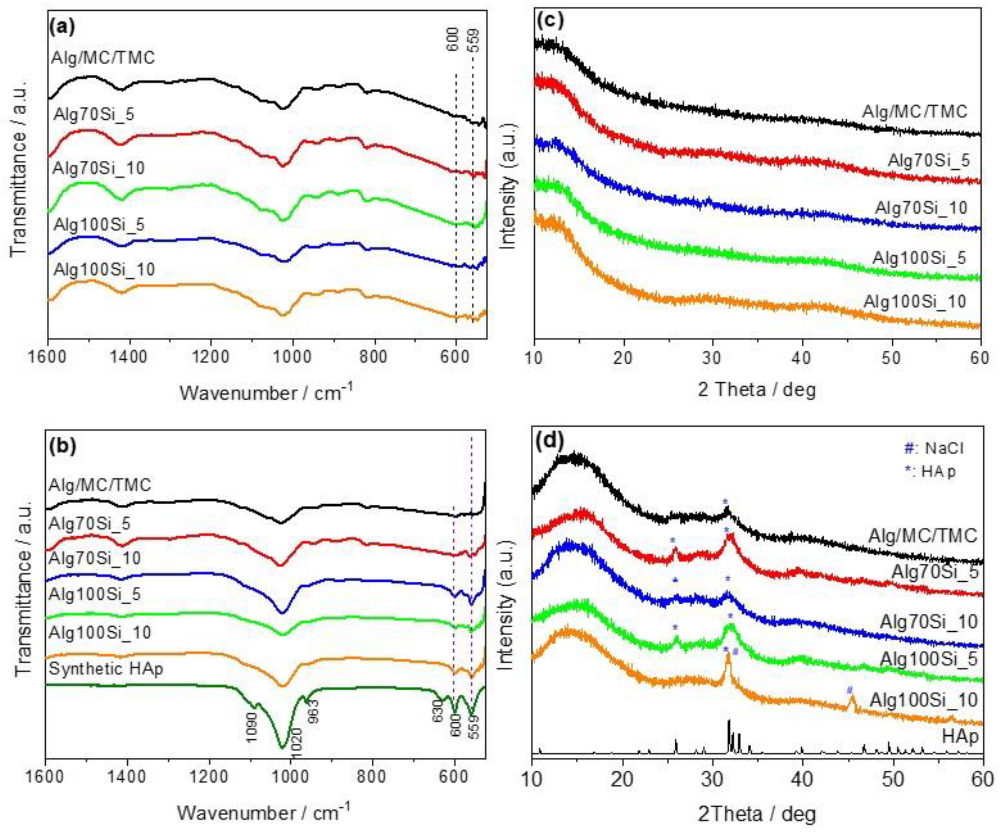
3.6. In Vitro Bioactivity Study

The term bioactivity refers to the ability of an implant to form the calcium phosphate compound hydroxyapatite on its surface when it comes into contact with body fluids or with fluids that simulate those of the body (simulated body fluid, SBF). SBF is an acellular and protein-free solution that has a composition of inorganic species similar to that of blood plasma. In order to accelerate the mineralization time, many modified SBF solutions have been used in the literature [35]. In the present work, twice simulated SBF (2xSBF) was used by doubling calcium and phosphorous concentrations in comparison with SBF solution [20]. Mineralization of scaffolds with hydroxyapatite improves their structural stability and makes these materials more biocompatible, enhancing osteoblast adhesion and osteointegration [36].
The FTIR spectra of all samples are shown in Figure 5a. The spectrum of Alg/MC/TMC in the spectral range between 525 and 1600 cm−1 is characterized by two characteristic vibrations of alginate due to the carboxylate group, an antisymmetric stretch at 1596 cm−1, and a symmetric stretch at 1410 cm−1 [37]. The spectrum also shows the characteristic cellulose peaks in the range 1000–1200 cm−1 and the ring stretching peak at 943 cm−1 [38]. In the case of composite samples, the characteristic peak of the asymmetric stretching of the Si-O-Si group is hardly distinguished due to overlapping with peaks attributed to alginate and methylcellulose. The FTIR spectra of the samples after immersion in 2xSBF solution together with the spectrum of synthetic HAp are shown in Figure 5b. The peaks observed in the spectrum of synthetic HAp are attributed as follows: The bands at 600 (s), 559 (s), and ~1020 (vs) cm−1 are assigned to the vibrations of the phosphate group. Specifically, the peaks at 600 (s) and 559 (s) are related to the triple-degenerated vibration of the O-P-O bond. The third component should appear at 574 cm−1 (s, sh). The band at ~1020 (vs) cm−1 is assigned to the stretching vibration of the P-O bond, while the band at 630 cm−1 is assigned to the hydroxyl libration mode. The peaks at 963 and 1090 cm−1 are attributed to the non-degenerated, symmetrical stretching vibration and to the antisymmetric stretching modes of the P-O bond in the phosphate group [39].
Through comparison of the FTIR spectra of the scaffolds after their exposure to SBF solution with the reference spectrum of HAp, the presence of HAp is evident from the absorption peaks at 600 and 559 cm−1. The presence of the above peaks is observed in all samples; however, their intensity is lower in sample Alg/MC/TMC and composite samples containing 5% glasses. The presence of phosphate vibrational modes in the 1000–1100 cm−1 range is difficult to be distinguished due to overlapping with the peaks of alginates and MC.
In addition to FTIR spectroscopy, the X-ray diffraction technique was used to characterize the formation of HAp on the scaffolds after exposure to SBF solution. Figure 5c,d show the XRD graphs of the samples before and after immersion in the solution. The amorphous phase of all samples is observed in Figure 5c. All scaffolds, except for sample Alg100Si10, after immersion in SBF show the characteristic reflections at 2θ at 26° and 31° attributed to the (002) and (211) planes of HAp. The standard JCPDS (Joint Committee on Powder Diffraction Standards) card No 9-432 of HAp is also shown for comparison. The samples containing the bioactive glass 70Si30Ca show the highest intensity at 2θ: 26°, indicating that the presence of bioactive glasses affects the in vitro bioactivity.
Although the samples were washed, diffraction peaks of NaCl are present in sample Alg/100Si10. The peaks are attributed to the crystallization of sodium chloride entrapped inside the hydrogel. The peaks assigned to NaCl (Halite) are observed at 2θ: 27.3° and 45.4°. The diffraction peak at 31.7° overlaps with the characteristic peaks of HAp at the same area. However, due to peak broadening, the presence of HAp can be identified.
Figure 6 shows the SEM images of samples before (a–e) and after (f–o) immersion in 2xSBF solution for 2 weeks. Before immersion, the images reveal the 3D-printed structure of scaffolds which is characterized by the presence of clearly defined pores. Due to the lyophilization process, no shrinkage or other textural abnormalities were observed. Samples incubated in SBF solution (f–j) are covered with a dense layer of HAp. The SEM micrographs at higher magnifications (k–o) revealed that the HAp layer consisted of spherical aggregates. In another study, pure alginate 3D-printed scaffolds were soaked for 10 days in SBF, and no apatite formation was observed. However, the presence of 13–93 bioactive glass resulted in apatite mineralization [12]. Although pure alginate hydrogels did not show mineralization after incubation in SBF, the presence of other biopolymers in their network induced apatite formation. For example, cellulose nanofibril incorporation in alginate hydrogels results in apatite formation after immersion in SBF solution [40]. It has also been shown that alginate–starch aerogels are bioactive materials since the formation of HAp is induced even after one day of immersion in SBF. The precipitation is attributed to the parallel presence of calcium ions within the alginate network and the phosphate ions in SBF solution [41].

3.7. Biological Characterization of the Scaffolds

3.7.1. Viability of Pre-Osteoblastic Cells within Scaffolds

The viability and proliferation of the MC3T3-E1 pre-osteoblastic cells on the five scaffold compositions were quantitatively determined using the colorimetric PrestoBlue® viability assay during 2 and 7 days in cell culture according to the ISO 10993-5 (2009) standards (Figure 7). Cell viability values on each scaffold composition were statistically evaluated and compared with the Alg/MC/TMC control scaffold at each experimental time point. On day 2, the number of viable cells was comparable for all four modified scaffolds and the Alg/MC/TMC control, and no significant differences were observed. After 7 days of culture, all four modified scaffolds presented a similar effect on cell proliferation, proportional to the Alg/MC/TMC control (Figure 7). These results indicate that the incorporation of alginate-based bioinks with conventional glasses (100% SiO2) or bioactive glasses (70%Si-30%CaO) does not negatively impact the viability and proliferation of pre-osteoblastic cells, while an increase in the concentration appears to be associated with a significant increase in cell proliferation (p < 0.01). A similarly strong cell adhesion and a high viability and proliferation increase from day 2 up to day 21 were observed in crosslinked alginate/chitosan scaffolds seeded with human nucleus pulposus cells and dental pulp stem cells, rendering alginate and chitosan suitable biomaterials for the fabrication of 3D porous scaffolds for bone and cartilage tissue engineering [42].

3.7.2. Cell Morphology on Scaffolds

Cell attachment is the initial step in a cascade of cell–biomaterial interactions and is important to cellular processes such as cell guidance, proliferation, and differentiation [43]. In this context, the ability of pre-osteoblastic cells to adhere and infiltrate into the pores of the scaffolds after 4 and 10 days in culture was determined by means of SEM (Figure 8). Four days after cell seeding, pre-osteoblasts grew within the pores of the scaffolds, without displaying their characteristic elongated morphology, however. From day 4 in culture, a high cell density was observed that was similar in all scaffold compositions, and this was maintained on day 10. Based on these results that demonstrate the ability of the scaffolds to support cell attachment and infiltration into their pores, we performed further in vitro biological assessments using these scaffolds.

3.7.3. ALP Activity of Pre-Osteoblastic Cells on Scaffolds

The ALP activity results indicate similar values for all scaffold compositions, without significant changes between days 3 and 7 (Figure 9). On day 7, higher values were observed for the bioglass-containing scaffolds than for Alg/MC/TMC. The statistical analysis of the normalized ALP activity values indicated non-significant differences among the different scaffold compositions at each time point, suggesting their capacity to support osteogenic responses.

3.7.4. Collagen Production by the MC3T3-E1 Pre-Osteoblastic Cells

A hallmark of osteoblast differentiation both in vivo and in vitro is the formation of an extracellular matrix (ECM) [44]. Type I collagen accounts for about 95% of the organic matrix proteins in bone. In order to examine the potential of the MC3T3-E1 pre-osteoblasts cultured on the Alg/SiO2 scaffolds to differentiate into mature osteoblasts in vitro, we investigated the effect of collagen production as a predominant protein during ECM formation, by quantifying the levels of total collagen secreted by the pre-osteoblastic cells. Figure 10 demonstrates that all modified Alg/SiO2 scaffolds significantly enhanced collagen production on day 7 compared to the Alg/MC/TMC control surface (p < 0.01) and thus supported ECM formation. Another study applying alginate/chitosan gel-like porous scaffolds loaded with dental pulp stem cells (DPSCs) reported increased ECM formation and a significant increase in the gene expression of fibrocartilaginous markers including collagen types I and X, aggrecan, SOX9, and cartilage oligomeric matrix protein after three weeks in culture, suggesting the ability of the biomaterials to promote temporomandibular (TMJ) joint disc regeneration [42]. In the same report, dynamic thermomechanical analysis revealed that alginate/chitosan scaffolds loaded with DPSCs significantly increased the storage modulus and elastic response compared to cell-free scaffolds, indicating similar values to those of native TMJ discs.

4. Conclusions

In the present work, a low-cost 3D printer for printing hydrogels composed of biopolymers was constructed by modification of a conventional FFF 3D printer. Hydrogel inks comprising alginate/methyl cellulose/trimethyl chitosan (TMC) showed significant higher stability in comparison with alginate/methyl cellulose inks. This can be attributed to electrostatic interactions between alginate and TMC alginate polymeric chains. The incorporation of pure silicate or bioactive glasses containing 30% mole CaO retained the stability of the alginate/MC/TMC scaffolds in normal saline solutions. Immersion in 2xSBF solution stabilized the structure for at least two weeks. The possible mechanism leading to this stability is based on the formation of apatite crystals in the polymeric network. Pre-osteoblastic cells seeded on the scaffolds with different compositions revealed a good cell adhesion, an increased proliferation up to seven days in culture, and a similar ALP activity. The production of total collagen was found to be significantly higher in scaffolds containing silica and bioactive glasses, demonstrating their ability to promote extracellular matrix formation. In conclusion, 3D-printed porous scaffolds containing alginate/methyl cellulose/trimethyl chitosan reinforced with pure silica or bioactive glasses are promising candidates for bone tissue engineering applications.

Author Contributions

Conceptualization, N.B.; methodology, experimental work, and data analysis, N.B., M.F., C.K., P.Z., D.F., V.P., R.-M.K.; writing—original draft preparation, N.B., V.P.; writing—review and editing, N.B., D.F., M.C.; visualization, N.B., D.F., C.K., M.C.; funding acquisition, M.C. All authors have read and agreed to the published version of the manuscript.

Funding

This research received funding by the Hellenic Foundation for Research and Innovation (H.F.R.I.) under the “1st Call for H.F.R.I. Research Projects to support Faculty members and Researchers and the procurement of high-cost research equipment grant” (project number HFRI-FM17-1999).

Institutional Review Board Statement

Not applicable.

Informed Consent Statement

Not applicable.

Data Availability Statement

The data presented in this study are available on request from the corresponding authors.

Conflicts of Interest

The authors declare no conflict of interest.

References

  1. Su, X.; Wang, T.; Guo, S. Applications of 3D printed bone tissue engineering scaffolds in the stem cell field. Regen. Ther. 2021, 16, 63–72. [Google Scholar] [CrossRef] [PubMed]
  2. Hull, C.W. Apparatus for Production of Three-Dimensional Objects by Stereolithography. U.S. Patent 4575330 A, 11 March 1986. [Google Scholar]
  3. Hutmacher, D.W.; Sittinger, M.; Risbud, M.V. Scaffold-based tissue engineering: Rationale for computer-aided design and solid free-form fabrication systems. Trends Biotechnol. 2004, 22, 354–362. [Google Scholar] [CrossRef] [PubMed]
  4. Łabowska, M.B.; Michalak, I.; Detyna, J. Methods of extraction, physicochemical properties of alginates and their applications in biomedical field—A review. Open Chem. 2019, 7, 738–762. [Google Scholar] [CrossRef] [Green Version]
  5. Jang, T.S.; Jung, H.D.; Pan, H.M.; Han, W.T.; Chen, S.; Song, J. 3D printing of hydrogel composite systems: Recent advances in technology for tissue engineering. Int. J. Bioprinting 2018, 4, 1–28. [Google Scholar] [CrossRef] [PubMed]
  6. Liu, S.; Bastola, A.K.; Li, L. A 3D printable and mechanically robust hydrogel based on alginate and graphene oxide. ACS Appl. Mater. Interfaces 2017, 9, 41473–41481. [Google Scholar] [CrossRef]
  7. Ahlfeld, T.; Cidonio, G.; Kilian, D.; Duin, S.; Akkineni, A.R.; Dawson, J.I.; Yang, S.; Lode, A.; Oreffo, R.O.C.; Gelinsky, M. Development of a clay based bioink for 3D cell printing for skeletal application. Biofabrication 2017, 9, 034103. [Google Scholar] [CrossRef]
  8. You, F.; Chen, X.; Cooper, D.M.L.; Chang, T.; Eames, B.F. Homogeneous hydroxyapatite/alginate composite hydrogel promotes calcified cartilage matrix deposition with potential for three-dimensional bioprinting. Biofabrication 2019, 11, 015015. [Google Scholar] [CrossRef]
  9. Luo, Y.; Lode, A.; Wu, C.; Chang, J.; Gelinsky, M. Alginate/nanohydroxyapatite scaffolds with designed core/shell structures fabricated by 3D plotting and in situ mineralization for bone tissue engineering. ACS Appl. Mater. Interfaces 2015, 7, 6541–6549. [Google Scholar] [CrossRef]
  10. Baino, F.; Hamzehlou, S.; Kargozar, S. Bioactive glasses: Where are we and where are we going? J. Funct. Biomater. 2018, 9, 25. [Google Scholar] [CrossRef] [PubMed] [Green Version]
  11. Martinez, A.; Izquierdo-Barba, I.; Vallet-Regi, M. Bioactivity of a CaO-SiO2 binary glasses system. Chem. Mater. 2000, 12, 3080–3088. [Google Scholar] [CrossRef]
  12. Luo, G.; Ma, Y.; Cui, X.; Jiang, L.; Wu, M.; Hu, Y.; Luo, Y.; Pan, H.; Ruan, C. 13-93 bioactive glass/alginate composite scaffolds 3D printed under mild conditions for bone regeneration. RSC Adv. 2017, 7, 11880–11889. [Google Scholar] [CrossRef] [Green Version]
  13. Wang, X.; Tolba, E.; Der, H.C.S.; Neufurth, M.; Feng, Q.; Diehl-Seifert, B.R.; Mü Ller, W.E.G. Effect of bioglass on growth and biomineralization of saos-2 cells in hydrogel after 3d cell bioprinting. PLoS ONE 2014, 9, 1–7. [Google Scholar] [CrossRef]
  14. Contessi Negrini, N.; Bonetti, L.; Contili, L.; Farè, S. 3D printing of methylcellulose-based hydrogels. Bioprinting 2018, 10, 1–10. [Google Scholar] [CrossRef]
  15. Hamman, J.H.; Kotzé, A.F. Effect of the type of base and number of reaction steps on the degree of quaternization and molecular weight of N-trimethyl chitosan chloride. Drug Dev. Ind. Pharm. 2001, 27, 373–380. [Google Scholar] [CrossRef]
  16. Mystiridou, E.; Patsidis, A.C.; Bouropoulos, N. Development and characterization of 3D printed multifunctional bioscaffolds based on PLA/PCL/HAp/BaTiO3 composites. Appl. Sci. 2021, 11, 4253. [Google Scholar] [CrossRef]
  17. Kontogiannidou, E.; Meikopoulos, T.; Virgiliou, C.; Bouropoulos, N.; Gika, H.; Vizirianakis, I.S.; Müllertz, A.; Fatouros, D.G. Towards the development of self-nano-emulsifying drug delivery systems (SNEDDS) containing trimethyl chitosan for the oral delivery of amphotericin B: In vitro assessment and cytocompatibility studies. J. Drug Deliv. Sci. Technol. 2020, 56, 101524. [Google Scholar] [CrossRef]
  18. Saravanapavan, P.; Hench, L.L. Low-temperature synthesis, structure, and bioactivity of gel-derived glasses in the binary CaO-SiO2 system. J. Biomed. Mater. Res. 2001, 54, 608–618. [Google Scholar] [CrossRef]
  19. Chrissanthopoulos, A.; Bouropoulos, N.; Yannopoulos, S.N. Vibrational spectroscopic and computational studies of sol-gel derived CaO-MgO-SiO2 binary and ternary bioactive glasses. Vib. Spectrosc. 2008, 48, 118–125. [Google Scholar] [CrossRef]
  20. Girija, E.K.; Parthiban, S.P.; Suganthi, R.V.; Elayaraja, K.; Joshy, M.I.A.; Vani, R.; Kularia, P.; Asokan, K.; Kanjilal, D.; Yokogawa, Y.; et al. High energy irradiation—A tool for enhancing the bioactivity of Hydroxyapatite. J. Ceram. Soc. Japan 2008, 116, 320–324. [Google Scholar] [CrossRef] [Green Version]
  21. Georgopoulou, A.; Papadogiannis, F.; Batsali, A.; Marakis, J.; Alpantaki, K.; Eliopoulos, A.G.; Pontikoglou, C.; Chatzinikolaidou, M. Chitosan/gelatin scaffolds support bone regeneration. J. Mater. Sci. Mater. Med. 2018, 29, 59. [Google Scholar] [CrossRef]
  22. Hadjicharalambous, C.; Mygdali, E.; Prymak, O.; Buyakov, A.; Kulkov, S.; Chatzinikolaidou, M. Proliferation and osteogenic response of MC3T3-E1 pre-osteoblastic cells on porous zirconia ceramics stabilized with magnesia or yttria. J. Biomed. Mater. Res. Part A 2015, 103, 3612–3624. [Google Scholar] [CrossRef]
  23. Hadjicharalambous, C.; Buyakov, A.; Buyakova, S.; Kulkov, S.; Chatzinikolaidou, M. Porous alumina, zirconia and alumina/zirconia for bone repair: Fabrication, mechanical and in vitro biological response. Biomed. Mater. 2015, 10. [Google Scholar] [CrossRef] [PubMed]
  24. Walsh, B.J.; Thornton, S.C.; Penny, R.; Breit, S.N. Microplate reader-based quantitation of collagens. Anal. Biochem. 1992, 203, 187–190. [Google Scholar] [CrossRef]
  25. Tullberg-Reinert, H.; Jundt, G. In situ measurement of collagen synthesis by human bone cells with a Sirius Red-based colorimetric microassay: Effects of transforming growth factor β2 and ascorbic acid 2-phosphate. Histochem. Cell Biol. 1999, 112, 271–276. [Google Scholar] [CrossRef] [PubMed]
  26. Datta, S.; Sarkar, R.; Vyas, V.; Bhutoria, S.; Barui, A.; Roy Chowdhury, A.; Datta, P. Alginate-honey bioinks with improved cell responses for applications as bioprinted tissue engineered constructs. J. Mater. Res. 2018, 33, 2029–2039. [Google Scholar] [CrossRef]
  27. Kamitsos, E.I.; Patsis, A.P.; Kordas, G. Infrared-reflectance spectra of heat-treated sol-gel-derived silica. Phys. Rev. B 1993, 48, 12499. [Google Scholar] [CrossRef] [PubMed]
  28. Rouquerol, J.; Avnir, D.; Fairbridge, C.W.; Everett, D.H.; Haynes, J.M.; Pernicone, N.; Ramsay, F.; Sing, K.S.W.; Unger, K.K. Recommendations for the characterization of porous solids (Technical Report). Pure Appl. Chem. 1994, 66, 1739–1758. [Google Scholar] [CrossRef]
  29. Vallet-Regi, M.; Salinas, A.J.; Martínez, A.; Izquierdo-Barba, I.; Pérez-Pariente, J. Textural properties of CaO-SiO2 glasses for use in implants. Solid State Ionics 2004, 172, 441–444. [Google Scholar] [CrossRef]
  30. Jones, J.R.; Hench, L.L. Factors Affecting the Structure and Properties of Bioactive Foam Scaffolds for Tissue Engineering. J. Biomed. Mater. Res. Part B Appl. Biomater. 2004, 68, 36–44. [Google Scholar] [CrossRef]
  31. Lien, S.M.; Ko, L.Y.; Huang, T.J. Effect of pore size on ECM secretion and cell growth in gelatin scaffold for articular cartilage tissue engineering. Acta Biomater. 2009, 5, 670–679. [Google Scholar] [CrossRef]
  32. Pasparakis, G.; Bouropoulos, N. Swelling studies and in vitro release of verapamil from calcium alginate and calcium alginate-chitosan beads. Int. J. Pharm. 2006, 323, 34–42. [Google Scholar] [CrossRef] [PubMed]
  33. Cleetus, C.M.; Primo, F.A.; Fregoso, G.; Raveendran, N.L.; Noveron, J.C.; Spencer, C.T.; Ramana, C.V.; Joddar, B. Alginate hydrogels with embedded ZnO nanoparticles for wound healing therapy. Int. J. Nanomed. 2020, 15, 5097–5111. [Google Scholar] [CrossRef] [PubMed]
  34. Choe, G.; Oh, S.; Seok, J.M.; Park, S.A.; Lee, J.Y. Graphene oxide/alginate composites as novel bioinks for three-dimensional mesenchymal stem cell printing and bone regeneration applications. Nanoscale 2019, 11, 23275–23285. [Google Scholar] [CrossRef] [PubMed]
  35. Uchida, M.; Kim, H.M.; Kokubo, T.; Miyaji, F.; Nakamura, T. Bonelike Apatite Formation Induced on Zirconia Gel in a Simulated Body Fluid and Its Modified Solutions. J. Am. Ceram. Soc. 2001, 84, 2041–2044. [Google Scholar] [CrossRef]
  36. Venugopal, J.; Prabhakaran, M.P.; Zhang, Y.; Low, S.; Choon, A.T.; Ramakrishna, S. Biomimetic hydroxyapatite-containing composite nanofibrous substrates for bone tissue engineering. Philos. Trans. R. Soc. A Math. Phys. Eng. Sci. 2010, 368, 2065–2081. [Google Scholar] [CrossRef] [Green Version]
  37. Lawrie, G.; Keen, I.; Drew, B.; Chandler-Temple, A.; Rintoul, L.; Fredericks, P.; Grøndahl, L. Interactions between alginate and chitosan biopolymers characterized using FTIR and XPS. Biomacromolecules 2007, 8, 2533–2541. [Google Scholar] [CrossRef]
  38. Rangelova, N.; Radev, L.; Nenkova, S.; Salvado, I.M.M.; Fernandes, M.H.V.; Herzog, M. Methylcellulose/SiO2 hybrids: Sol-gel preparation and characterization by XRD, FTIR and AFM. Cent. Eur. J. Chem. 2011, 9, 112–118. [Google Scholar] [CrossRef]
  39. Rámila, A.; Vallet-Regí, M. Static and dynamic in vitro study of a sol-gel glass bioactivity. Biomaterials 2001, 22, 2301–2306. [Google Scholar] [CrossRef]
  40. Abouzeid, R.E.; Khiari, R.; Beneventi, D.; Dufresne, A. Biomimetic mineralization of three-dimensional printed alginate/TEMPO-Oxidized cellulose nanofibril scaffolds for bone tissue engineering. Biomacromolecules 2018, 19, 4442–4452. [Google Scholar] [CrossRef] [PubMed]
  41. Martins, M.; Barros, A.A.; Quraishi, S.; Gurikov, P.; Raman, S.P.; Smirnova, I.; Duarte, A.R.C.; Reis, R.L. Preparation of macroporous alginate-based aerogels for biomedical applications. J. Supercrit. Fluids 2015, 106, 152–159. [Google Scholar] [CrossRef] [Green Version]
  42. Bousnaki, M.; Bakopoulou, A.; Papadogianni, D.; Barkoula, N.M.; Alpantaki, K.; Kritis, A.; Chatzinikolaidou, M.; Koidis, P. Fibro/chondrogenic differentiation of dental stem cells into chitosan/alginate scaffolds towards temporomandibular joint disc regeneration. J. Mater. Sci. Mater. Med. 2018, 29, 97. [Google Scholar] [CrossRef] [PubMed]
  43. Ruoslahti, E.; Öbrink, B. Common principles in cell adhesion. Exp. Cell Res. 1996, 227, 1–11. [Google Scholar] [CrossRef]
  44. Quarles, L.D.; Yohay, D.A.; Lever, L.W.; Caton, R.; Wenstrup, R.J. Distinct proliferative and differentiated stages of murine MC3T3-E1 cells in culture: An in vitro model of osteoblast development. J. Bone Miner. Res. 1992, 7, 683–692. [Google Scholar] [CrossRef] [PubMed]
Figure 1. Rheological characterization of the prepared hydrogels: (a) mechanical spectra of all samples recorded at 25 °C (0.5% strain), and (b) steady-state flow curves of the hydrogels.
Applsci 11 08677 g001
Figure 2. XRD diffractograms (a), and FTIR (b) and Raman spectra (c) of 100Si and 70Si30Ca glasses.
Applsci 11 08677 g002
Figure 3. Optical microscope images of the lyophilized 3D-printed scaffolds according to formulations shown in Table 1 (A), and histogram showing the mean pore sizes of the scaffolds (B). Scale bar is equal to 5 mm.
Applsci 11 08677 g003
Figure 4. Swelling behavior of pure polysaccharide scaffolds (a) and composite scaffolds together with the sample containing TMC for comparison (b).
Applsci 11 08677 g004
Figure 5. FTIR and XRD graphs of samples before (a,c) and after (b,d) immersion in 2xSBF solution for 2 weeks. The FTIR spectrum of synthetic HAp and standard JCPDS card No 9-432 of HAp are also shown for comparison.
Applsci 11 08677 g005
Figure 6. SEM images of samples before (ae) and after (fo) immersion in 2xSBF solution for 2 weeks.
Applsci 11 08677 g006
Figure 7. Cytotoxicity assessment of the five scaffold compositions. Cell metabolic activity of MC3T3-E1 pre-osteoblasts is expressed as absorbance units. The values represent means ± standard deviations of triplicates (n = 3), and the asterisks indicate statistical significance compared to the Alg/MC/TMC control surface at each experimental time point (*: p < 0.05, **: p < 0.01).
Applsci 11 08677 g007
Figure 8. Scanning electron micrographs illustrating MC3T3-E1 cell adhesion and growth on Alg/MC/TMC, Alg70Si_5, Alg70Si_10, Alg100Si_5, and Alg100Si_10 during 4 and 10 days of cell culture. Original magnifications are ×500.
Applsci 11 08677 g008
Figure 9. Alkaline phosphatase activity of MC3T3-E1 pre-osteoblastic cells on the five scaffold compositions after 3 and 7 days in culture. The values represent means ± standard deviations of triplicates (n = 3). Statistical analysis revealed no significant differences among the five scaffold compositions at each time point.
Applsci 11 08677 g009
Figure 10. Levels of total collagen produced by MC3T3-E1 pre-osteoblastic cells cultured on the five scaffolds for 4 and 7 days. The values represent means ± standard deviations of triplicates (n = 3), and the asterisks indicate statistical significance compared to the Alg/MC/TMC control surface at each experimental time point (**: p < 0.01, ****: p < 0.0001).
Applsci 11 08677 g010
Table 1. Composition of the prepared formulations.
SampleNaAlg
% w/v
MC
% w/v
TMC
% w/v
100%Si
% w/w
70Si30Ca
% w/w
Alg/MC102------
Alg/MC/TMC1021----
Alg100Si_10102110--
Alg100Si_510215--
Alg70Si_101021--10
Alg70Si_51021--5
Table 2. Specific surface area, pore volume, and pore diameter of the glasses prepared in the present work and the literature.
SampleSSA
m2/g
Total Pore Volume
cm3/g
Mean Pore Diameter
nm
Reference
100Si 377.040.262.79present work
100Si679.80.432.55[18]
70Si30Ca 108.260.4014.82present work
70Si30Ca126.00.4611.00[29]
70Si30Ca137.870.4014.82[18]
Publisher’s Note: MDPI stays neutral with regard to jurisdictional claims in published maps and institutional affiliations.

