
A Novel Approach of Studying the Fluid–Structure–Thermal Interaction of the Piston–Cylinder Interface of Axial Piston Pumps

Abstract
:1. Introduction
2. Modeling
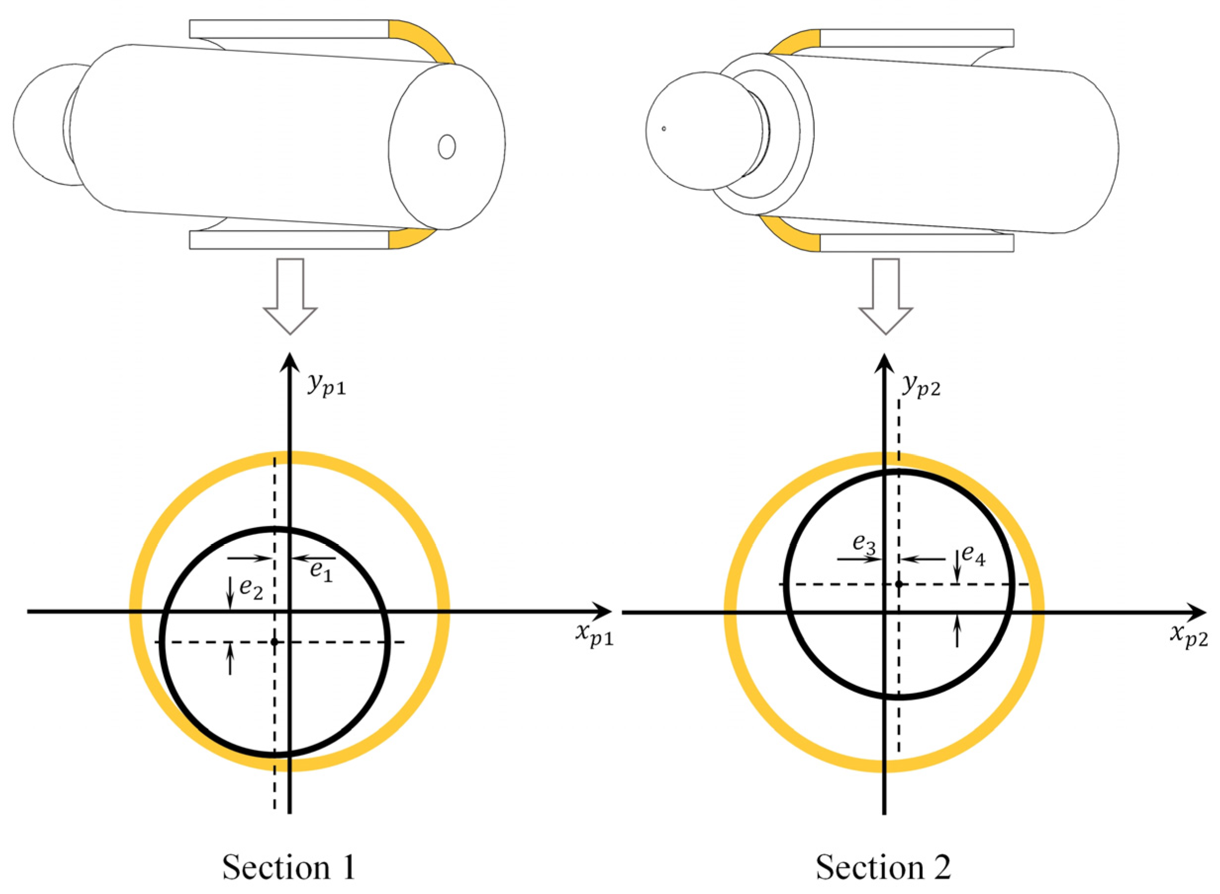
2.1. Film Geometry
2.2. The Reynolds Equation and Energy Equation
2.3. Finite Volume Method
2.4. Fluid–Structure–Thermal Interaction
2.5. Dynamic Model
2.5.1. The Force Exerted on the Piston
2.5.2. The Extra Friction Force
3. Results and Discussion
3.1. The Influence of Temperature
3.2. Axial Friction Force
3.3. Leakage of the Piston–Cylinder Interface
3.4. Discussion
4. Conclusions
- (1)
- The temperature greatly influences the lubrication performance. The dynamic viscosity will drop by 73% when the temperature rises from 293.15 K to 323.25 K at the pressure of 0.1 MPa. This will lead to the decrease in the film’s load-bearing capacity and the increase in the leakage;
- (2)
- Insufficient film height brings extra friction force, which is related to the pressure in the area;
- (3)
- A dynamic model of the piston–cylinder interface integrated the temperature and elastic deformation effects can accurately predict the friction force.
Author Contributions
Funding
Institutional Review Board Statement
Informed Consent Statement
Data Availability Statement
Acknowledgments
Conflicts of Interest
References
- Wieczorek, U.; Ivantysynova, M. Computer Aided Optimization of Bearing and Sealing Gaps in Hydrostatic Machines—The Simulation Tool Caspar. Int. J. Fluid Power 2002, 3, 7–20. [Google Scholar] [CrossRef]
- Pelosi, M. An Investigation of the Fluid-Structure Interaction of Piston/Cylinder Interface. Dissertations & Theses-Gradworks. 2012. Available online: https://www.proquest.com/docview/1237999091 (accessed on 16 February 2012).
- Pelosi, M.; Ivantysynova, M. Heat Transfer and Thermal Elastic Deformation Analysis on the Piston/Cylinder Interface of Axial Piston Machines. J. Tribol. 2012, 134, 041101. [Google Scholar] [CrossRef]
- Pelosi, M.; Ivantysynova, M. A Geometric Multigrid Solver for the Piston–Cylinder Interface of Axial Piston Machines. Tribol. Trans. 2012, 55, 163–174. [Google Scholar] [CrossRef]
- Wang, Z.; Yuan, S.; Peng, Z. Numerical Analysis on the Temperature Distribution of Oil-film in Plunger Pair. Automot. Eng. 2013, 35, 781–784. [Google Scholar] [CrossRef]
- Wang, Z.; Yuan, S.; Peng, Z. Influence of Piston Spin on Film Load Capacity; Transaction of Beijing Institute of Technology: Beijing, China, 2012; Volume 32, pp. 381–385. [Google Scholar] [CrossRef]
- Hu, M.; Xu, B.; Zhou, W.; Xia, S. Modelling and Analysis of Dynamics Characteristics of Piston-Slipper Group of Axial Piston Pump; Transactions of The Chinese Society of Agricultural Machinery: Beijing, China, 2016; pp. 373–380. [Google Scholar] [CrossRef]
- Hu, M. Study on Power Losses and Design Technology for the Surface Topography of Friction Pairs of Axial Piston Pump, Ph.D. Thesis. Zhejiang University, Zhejiang, China, 2017.
- Wang, K. Micro-Motion and Lubrication Characteristics of Piston-Cylinder Interface in Axial Piston Pump; Harbin Institute of Technology: Harbin, China, 2019. [Google Scholar] [CrossRef]
- Jihai, J.; Kelong, W.; Zebo, W.; Yi, S. The Impact of Bushing Thickness on the Piston/Cylinder Interface in Axial Piston Pump. IEEE Access 2019, 7, 24971–24977. [Google Scholar] [CrossRef]
- Jiang, J.; Wang, K.; Yan, W.; Sun, Y. A novel fluid structure interaction model for the grooved piston-cylinder interface in axial piston pump. AIP Adv. 2019, 9, 055013. [Google Scholar] [CrossRef] [Green Version]
- Song, Y.; Ma, J.; Zeng, S. A Numerical Study on Influence of Temperature on Lubricant Film Characteristics of the Piston/Cylinder Interface in Axial Piston Pumps. Energies 2018, 11, 1842. [Google Scholar] [CrossRef] [Green Version]
- Zhang, J.; Liu, B.; Lü, R.; Yang, Q.; Dai, Q. Study on Oil Film Characteristics of Piston-Cylinder Pair of Ultra-High Pressure Axial Piston Pump. Processes 2020, 8, 68. [Google Scholar] [CrossRef] [Green Version]
- Li, F.; Wang, D.; Lv, Q.; Haidak, G.; Zheng, S. Prediction on the lubrication and leakage performance of the piston–cylinder interface for axial piston pumps. Proc. Inst. Mech. Eng. Part C J. Mech. Eng. Sci. 2019, 233, 5887–5896. [Google Scholar] [CrossRef]
- Quan, J.; Hong-Bo, Y.; Yong, Y.; Li-Ming, C.; Xian-Kai, C. Numerical Analysis of the Water Film Characteristics in the Eccentric State of a Radial Piston Pump. IEEE Access 2018, 6, 15274–15282. [Google Scholar] [CrossRef]
- Ma, J.; Li, Y.; Pan, Y. Performance Analysis and Mathematical Modeling of Temperature Field on Piston/Cylinder Assembly. J. Cent. South Univ. (Sci. Technol.) 2018, 49, 76–84. [Google Scholar]


| Parameters | Symbol | Value |
|---|---|---|
| Piston outer diameter (mm) [2] | 20.700 | |
| Bushing inner diameter (mm) [2] | 20.724 | |
| Piston height (mm) | 54 | |
| Swash plate inclination (°) | 17 | |
| Hydraulic fluid dynamic viscosity at 40 °C (cst) | 32 | |
| Friction coefficient | 0.02 | |
| Minimum film height (μm) | 2 |
| Operating Conditions | Condition 1 | Condition 2 | Condition 3 |
|---|---|---|---|
| The average temperature of the film (°C) | 53.0 | 54.9 | 55.7 |
| Change of the gap height (μm) | 0.95 | 1.01 | 1.20 |
| Average dynamic viscosity (Pa⋅s) | 0.020 | 0.019 | 0.019 |
Publisher’s Note: MDPI stays neutral with regard to jurisdictional claims in published maps and institutional affiliations. |
© 2021 by the authors. Licensee MDPI, Basel, Switzerland. This article is an open access article distributed under the terms and conditions of the Creative Commons Attribution (CC BY) license (https://creativecommons.org/licenses/by/4.0/).
Share and Cite
Zhou, J.; Li, T.; Wang, D. A Novel Approach of Studying the Fluid–Structure–Thermal Interaction of the Piston–Cylinder Interface of Axial Piston Pumps. Appl. Sci. 2021, 11, 8843. https://doi.org/10.3390/app11198843
Zhou J, Li T, Wang D. A Novel Approach of Studying the Fluid–Structure–Thermal Interaction of the Piston–Cylinder Interface of Axial Piston Pumps. Applied Sciences. 2021; 11(19):8843. https://doi.org/10.3390/app11198843
Chicago/Turabian StyleZhou, Junjie, Tianrui Li, and Dongyun Wang. 2021. "A Novel Approach of Studying the Fluid–Structure–Thermal Interaction of the Piston–Cylinder Interface of Axial Piston Pumps" Applied Sciences 11, no. 19: 8843. https://doi.org/10.3390/app11198843
APA StyleZhou, J., Li, T., & Wang, D. (2021). A Novel Approach of Studying the Fluid–Structure–Thermal Interaction of the Piston–Cylinder Interface of Axial Piston Pumps. Applied Sciences, 11(19), 8843. https://doi.org/10.3390/app11198843