Article

Influence of Blade Wrap Angle on the Hydrodynamic Radial Force of Single Blade Centrifugal Pump

School of Mechanical Engineering, Nantong University, Nantong 226019, China
*
Authors to whom correspondence should be addressed.
Appl. Sci. 2021, 11(19), 9052; https://doi.org/10.3390/app11199052
Submission received: 2 September 2021 / Revised: 24 September 2021 / Accepted: 26 September 2021 / Published: 28 September 2021
(This article belongs to the Special Issue The Advances in Fluid Mechanics)

Abstract

:
To investigate the effect of blade wrap angle on the hydrodynamic radial force of a single blade centrifugal pump, numerical simulation is conducted on the pumps with different blade wrap angles. The effect of the wrap angle on the external characteristics and the radial force of a single blade centrifugal pump was analyzed according to the simulation result. It is found that, with the increase of the blade wrap angle, the head and efficiency of the single blade centrifugal pump are improved, the H-Q curve becomes steeper, and the efficiency also increased gradually, while the high-efficiency area is narrowed. The blade wrap angle has a great effect on the radial force of the single blade centrifugal pump. When the blade wrap angle is less than 360°, the horizontal component of the radial force is negative and the value is reduced with the increase of the wrap angle of the blade. When the wrap angle is larger than 360°, the horizontal component of the radial force is positive and the value increases with the increase of the wrap angle. Under part-loading conditions, the radial force of the single blade pump is significantly reduced with the increase of the blade wrap angle. When the wrap angle is smaller than 360°, the radial force decreases with the flow rate increase. In the condition that the wrap angle is larger than 360°, the radial force increases with the flow rate increase.

1. Introduction

A single blade centrifugal pump has a good non-clogging performance, which is widely used in the process of wastewater treatment [1]. To improve the ability of the flow channel to pass particles and strip impurities, the impeller is designed with only one blade that has a very large wrap angle. Such a kind of non-axisymmetric structure brings different kinds of problems to the single blade centrifugal pump, such as larger radial force, shock, and vibrations than the traditional centrifugal pumps.
With the development of high-speed and high-capacity pumps, the safety and reliability of the centrifugal pump have attracted attention from engineers and researchers [2]. Unstable problems like shock and vibrations are usually caused by the unsteady flow characteristics in the pump, which is extensively investigated till now. Stepanoff and Biheller [3,4] first proposed the radial force empirical formula, which estimates the radial force experienced by the impeller based on the impeller geometric parameters, flow rate and head, but the empirical coefficient has certain limitations. Brennen [5,6,7,8] comprehensively and systematically tested the radial force of NASA high-speed liquid oxygen and liquid hydrogen turbo pumps in the United States. The effect of impeller eccentricity, front and rear pump cavity leakage, and vortex frequency on the radial force were analyzed to establish the mathematical model of the radial force. Guelich [9] summarized the reasons for the radial force of the pump in his review: the uneven distribution of the circumferential pressure of the impeller, the radial force generated by the labyrinth seal, the dynamic and static interference effect of the impeller guide vane (volute), the steady radial force, the specific speed of the pump, the type of impeller or guide vane, the geometric parameters of the impeller and the operating conditions are related. Boehning [10] compared the effects of single volute, annular volute, and double volute on the radial force of the blood pump using a combination of numerical simulation and experiment. At the designed flow conditions, the radial forces are equivalent in the case of single volute and annular volute, and all have large radial forces, while the double volutes have almost no radial forces. Alemi [11] analyzed the influence of different volute structures on the radial force based on numerical simulation. The results showed that when the volute diaphragm was at 270°, the radial force was the smallest in all flow rate conditions.
Due to the asymmetric structure of the impeller, the radial force problem of single blade centrifugal pumps is particularly prominent, which makes the pumps less stable and the vibration-induced noise is stronger. Benra [12,13,14,15] has carried out a lot of research on the flow characteristics and hydraulic induced vibration in single-channel centrifugal pumps. Aoki [16] measured the transient pressure distribution of an open single-blade centrifugal impeller and obtained the dynamic and static radial forces of the impeller. Nishi [17,18,19] conducted a lot of research on the radial force of the single blade centrifugal pump by combining numerical simulation and experiment. The radial force on the single blade impeller was measured by installing a force measuring ring at the bearing. The influence of the blade outlet angle and blade outlet width on the radial force was investigated. It was found that to increase the blade outlet width can reduce the averaged value of the radial force at part-loading conditions. The radial force is divided into the inertial term, momentum term, and pressure term. The calculation results are basically consistent with the numerical calculation pressure integral results.
Since the single blade centrifugal pump has only one blade, to select reasonable parameters for the impeller during the design process is of great importance. Tan analyzed the influence of blade wrap angle on a single-channel pump performance [20]. Chen analyzed the effect of blade inlet angle on a single blade centrifugal pump performance [21]. The wrap angle is one of the main parameters for the design of centrifugal pumps. However, research concerning the effect of the blade wrap angle on the hydrodynamic radial force and the reliability of single blade centrifugal pump is lacking. In the current research, unsteady simulation is conducted for single blade centrifugal pumps with different blade wrap angles, and the effects of these pumps are compared to reveal the relationship between the blade wrap angle and the pump performance.

2. Pump Model and Simulation Method

2.1. Pump Model

The pump model in this study is a single blade centrifugal pump which is the same as the author’s early paper [22]. The main design parameters are Qd = 20 m3/h, H = 11 m, rotational speed n = 2940 r/min, and the main geometry parameters are shown as Table 1. The impeller was 3D designed by Bladegen based on the main parameters, and the design process of single blade centrifugal impeller by Bladegen is shown in Figure 1. The blade wrap angle is an important parameter of a single blade centrifugal pump. Properly increasing the blade wrap angle can enhance the restriction of the impeller to the fluid, but an excessively large blade wrap angle will result in increased friction loss. In the current research, impellers with five different wrap angles are investigated, the values of the wrap angles are 300°, 330°, 360°, 390°, and 420°. Other parameters for the impellers are kept consistent, which is shown in Table 1.

2.2. Simulation Method

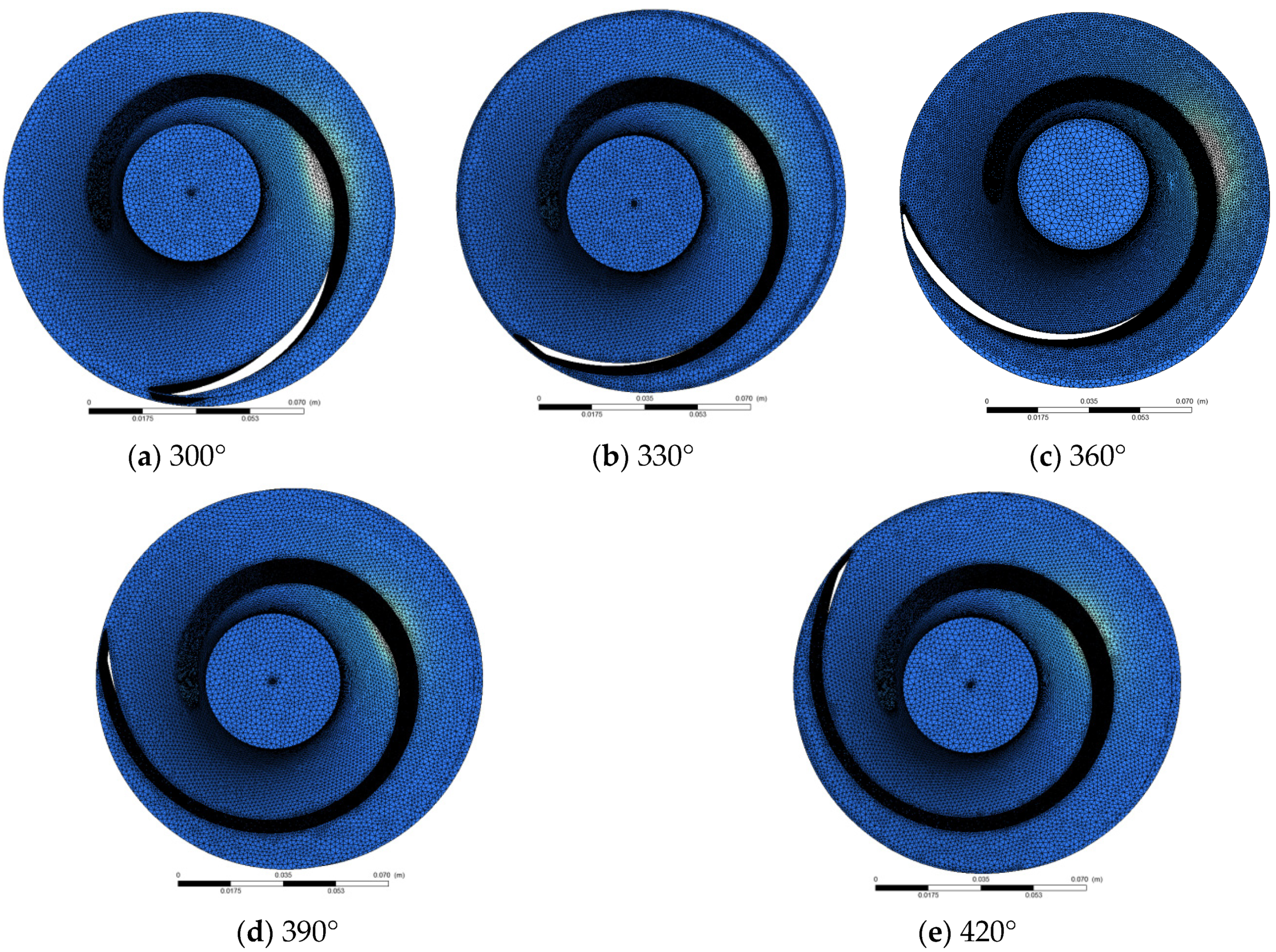
The simulation method is the same as the author’s early paper, which is validated by experiment [22]. The ICEM code was used to mesh the model, and tetrahedral mesh was used for the impeller. To improve the grid quality, we refined the wall boundary layer. Meshing results of the impellers are illustrated in Figure 2. The other calculation domains adopted the hexahedral structure mesh the same as the reference [22].
As the flow in the centrifugal pump has a high Reynolds number, the numerical simulation was adapted from the standard k-ε turbulence model [23,24,25,26]. ANSYS CFX 14.5 is used for numerical calculation, the coupling of velocity and pressure adopts the SIMPLEC algorithm, and the convection term adopts high-order format [27]. Using 25 °C water as the calculation medium, the solid wall is selected as a nonslip wall surface. Since the impeller and volute are castings, the surface roughness is set as 50 μm. The inlet is set to the total pressure inlet, and the outlet is set to the mass outlet. By setting different mass flows, the external characteristic curve of the pump can be obtained. A multi-coordinate reference system is adopted, the impeller is set to the rotating domain, the static domain is adopted for the others, and the interface between the dynamic and static domains is set to the frozen rotor. Considering the calculation time and accuracy, the convergence accuracy is set to 10−4.

2.3. Validation

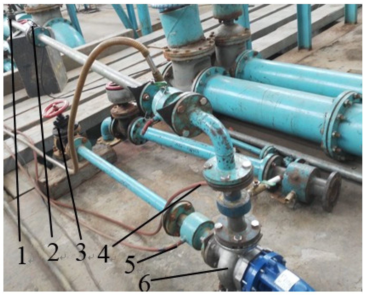
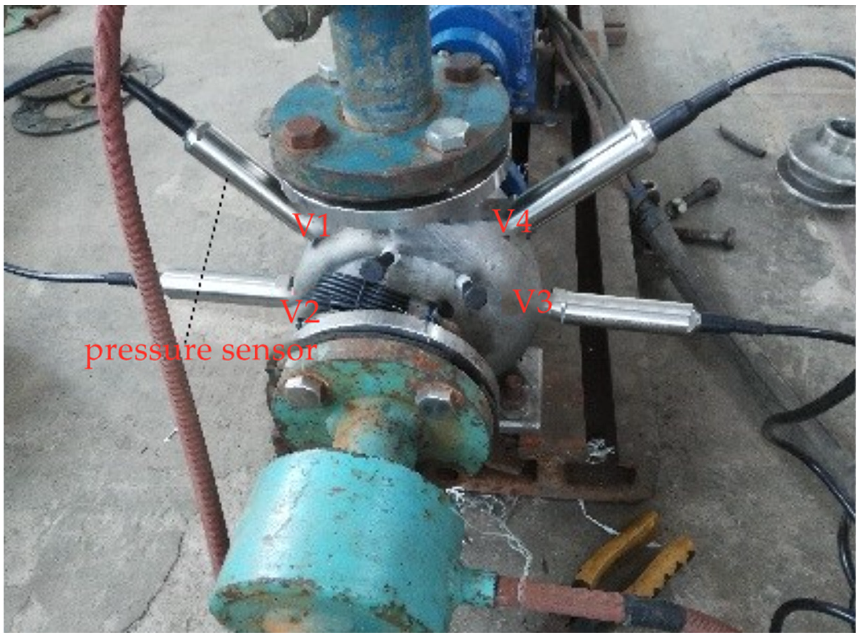
The experiment of a single blade centrifugal pump with 360° blade wrap angle was conducted [22]. Pump performance experimental setup and distribution of pressure sensors are shown in Figure 3 and Figure 4. The experimental device consists of the test pump, connecting pipes, valves, electromagnetic flowmeter and other components. Four pressure taps were located in the spiral volute wall. Pressure taps were instrumented with fast response pressure sensors (Figure 4), which provided absolute pressure values with an uncertainty of less than 0.1% according to the manufacturer’s data.
The pump performance curves of single blade centrifugal pump with 360° blade wrap angle were acquired by turn off or turn on the valve in the outlet. Figure 5 presents the results of CFD and experiment. The predicted power of CFD is hydraulic power, whereas the result of the experiment is total power. In order to compare with CFD results, based on the empirical coefficients of different power levels in the laboratory, the measured total efficiency is transformed into hydraulic efficiency. The experimental heads are smaller than numerical results, and it is less than 1 m. It can be observed that the CFD results are in good agreement with the experimental results.
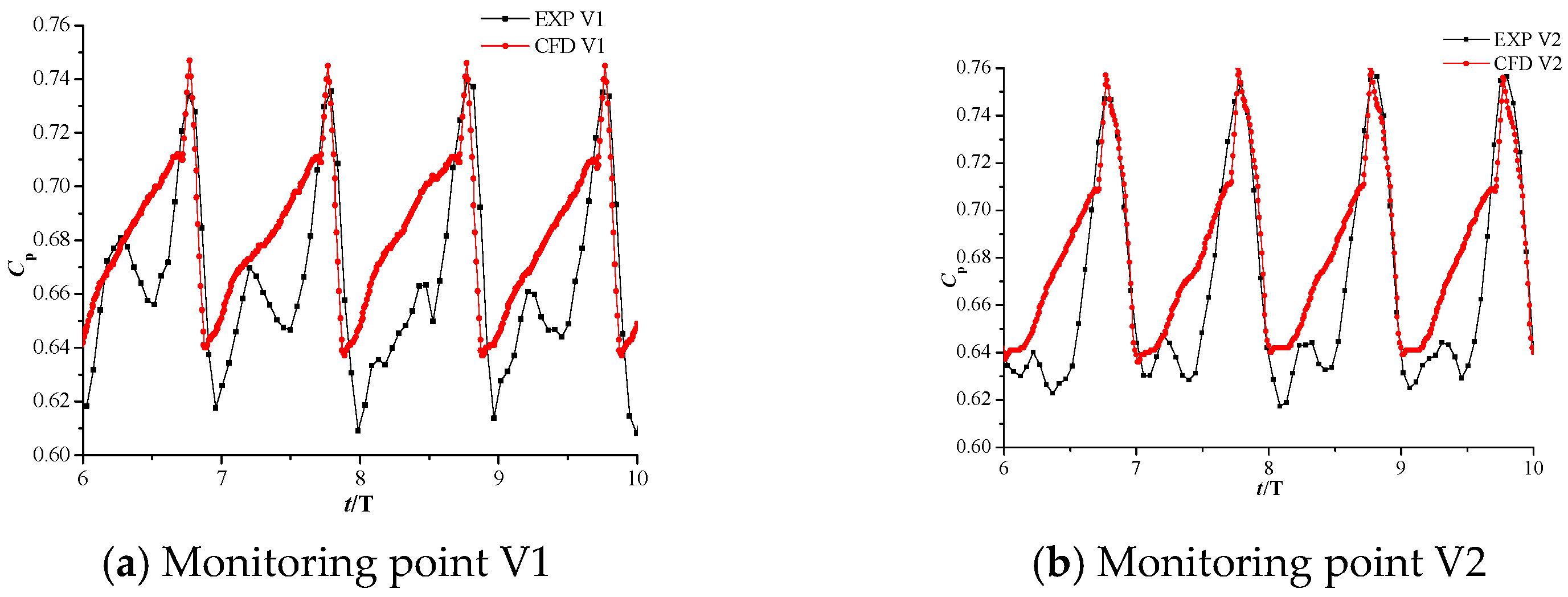
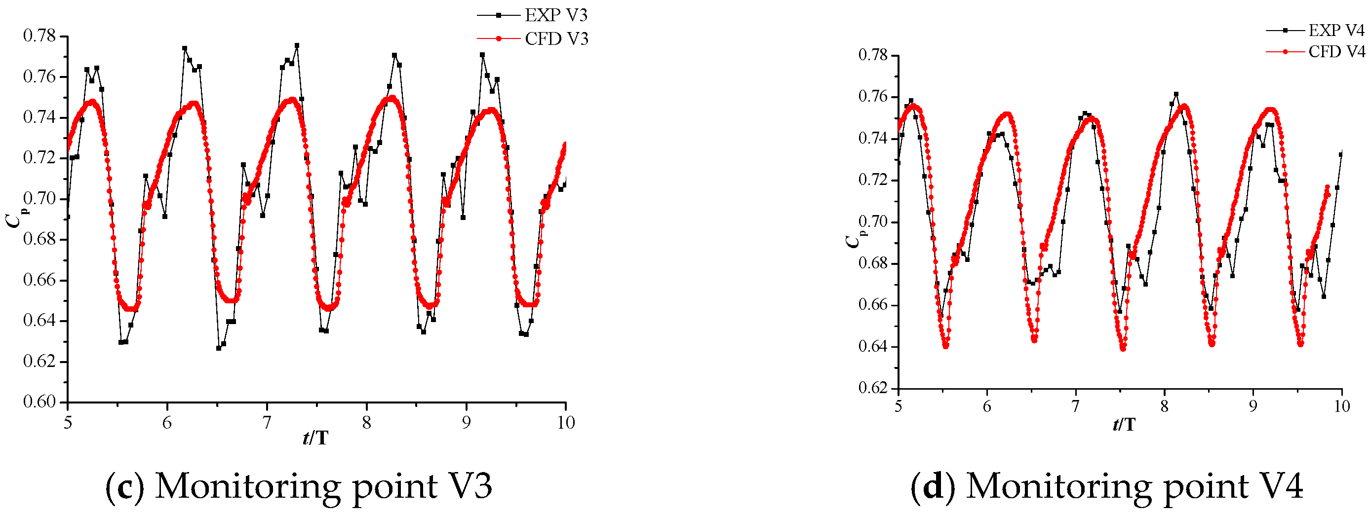
The pressure distribution of model 1 is presented in Figure 6 [22]. The CFD predicted pressures were similar to those obtained by experiment. The time history of the pressure in the numerical simulation approximately overlapped with the test results. The qualitative agreement of the pressure obtained by CFD numerical calculation and experiment was extremely high; and the CFD results show a reasonable agreement with the test data. Thus, numerical calculation results can be considered reliable.

3. Results and Discussion

3.1. Influence of Blade Wrap Angle on the External Characteristic

To analyze the effect of the wrap angle on the hydrodynamic radial force, five impellers were designed. The external characteristic curves of single blade centrifugal pumps with different blade wrap angles are shown in Figure 7. It can be seen from the figure that, as the blade wrap angle increases, the pump head tends to increase, and the H-Q curve becomes steeper, the pump efficiency increases gradually, but the high-efficiency area is narrowed. The P-Q curve becomes gentle with the increase of blade wrap angle. Generally, the head and efficiency of the single blade centrifugal pump are improved with the increase of blade wrap angle.
The turbulent dissipation rate cloud diagram of single blade centrifugal pump with different blade wrap angles at designed flow conditions are shown in Figure 8. It can be seen from the figure that the turbulence dissipation rate of single blade centrifugal pumps with blade wrap angle less than 360° is significantly higher. For other impellers, the dissipation rate changes no longer significantly after the wrap angle reaches 360°.
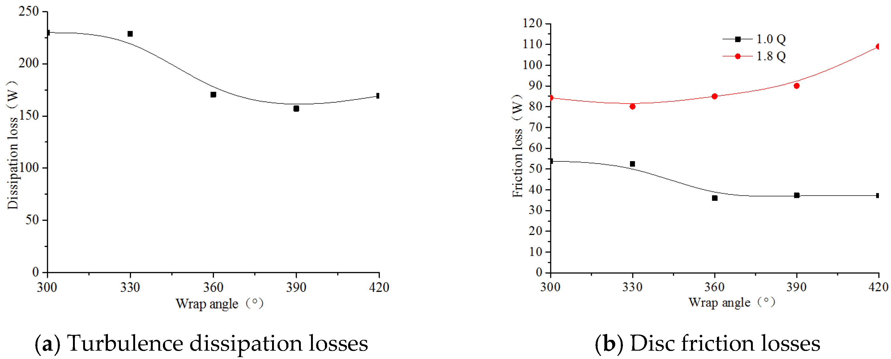
The turbulent dissipation losses in a single blade impeller with different blade wrap angles are shown in Figure 9a. It can be seen from the figure that the dissipation losses show a decreasing trend as the blade wrap angle increases, but after the wrap angle reaches 420°, the loss of dissipation has increased. The friction loss of the single blade centrifugal impeller with different wrap angles is shown in Figure 9b. As can be seen from the figure, under the designed flow rate conditions, the flow of the impeller continuously improves with the increase of the blade wrap angle, so the friction losses decrease with the wrap angle increase. However, under high flow rate conditions, because the friction surface increases with the increase of the wrap angle under high flow velocity, the friction loss increases with the increase of the wrap angle. Therefore, the efficiency of the single blade centrifugal pumps, which have a large wrap angle, decreases at large flow conditions, and its Q-η curve in the high-efficiency area becomes narrow.

3.2. Influence of Blade Wrap Angle on Radial Force

The blade wrap angle affects the pressure circular distribution in the impeller. As a result, the wrap angle is an important factor that affects the radial force of the single blade centrifugal pump. In this section, the effect of wrap angle on the radial force of the single blade centrifugal pump is investigated based on unsteady simulation. The unsteady simulation is validated by experiment and the simulation results agree well with the tested values [22]. In order to calculate the radial force, the impeller was divided as: FS, the front shroud; BS, back shroud; B, blade [28]. The Cartesian coordinates are used to specify the radial force. It is specified that the radial force in the positive X direction and the positive Y direction is positive; the corresponding forces in the negative X direction and the negative Y direction are negative, as shown in Figure 10.
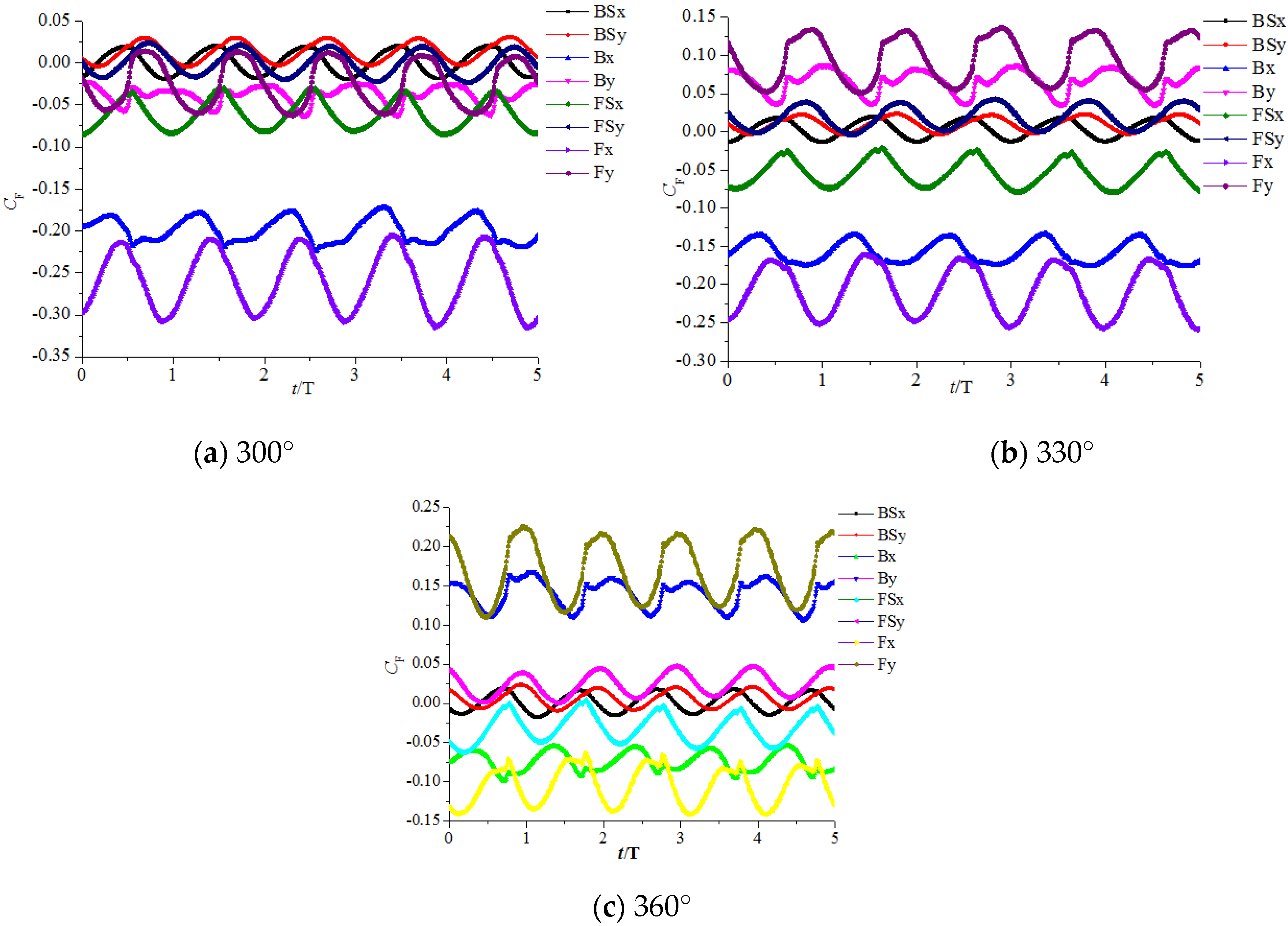
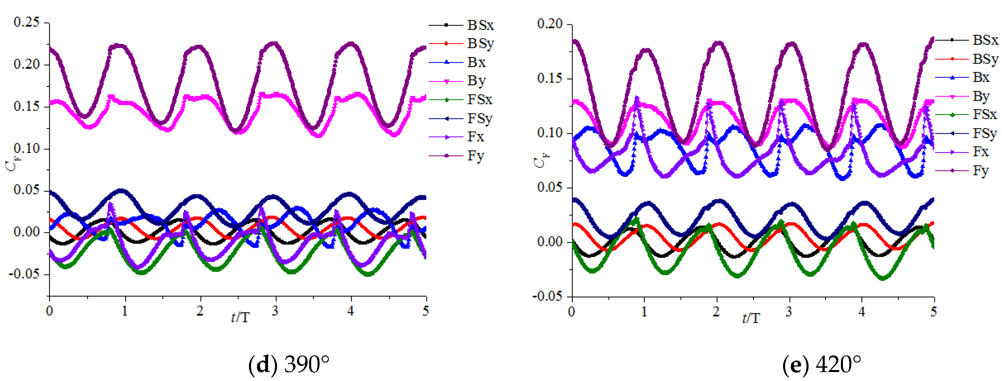
Figure 11 shows the time domain diagram of the radial force on the impeller of a single blade centrifugal pump with different blade wrap angles under design flow rate. It can be found from the figure, the radial force fluctuates periodically with the rotation of the impeller, and the periodicity is consistent. The radial force on the back shroud is small, and it does not change significantly with the variation of the wrap angle. The amplitude and direction of the x component of the radial force changes with the change of the blade wrap angle. When the blade wrap angle is 300°, 330° and 360°, the x component of the radial force is negative and the value decreases with the increase of the blade wrap angle. When the blade angle is larger than 390°, the x component of the radial force turns to positive and the value increases with the increase of the wrap angle. When the wrap angle is 360° and 390°, the y component of the radial force is the largest. When the wrap angle is 300° the y component of the radial force is the lowest.
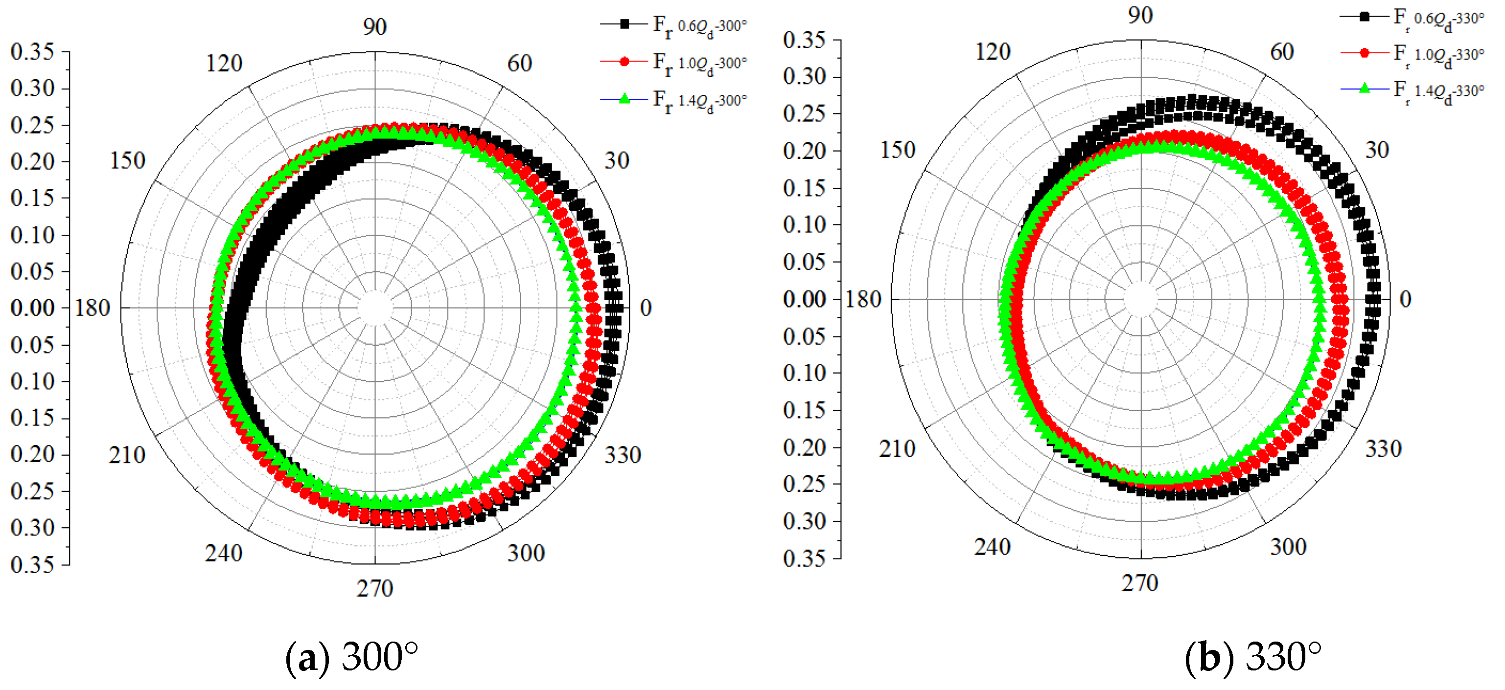
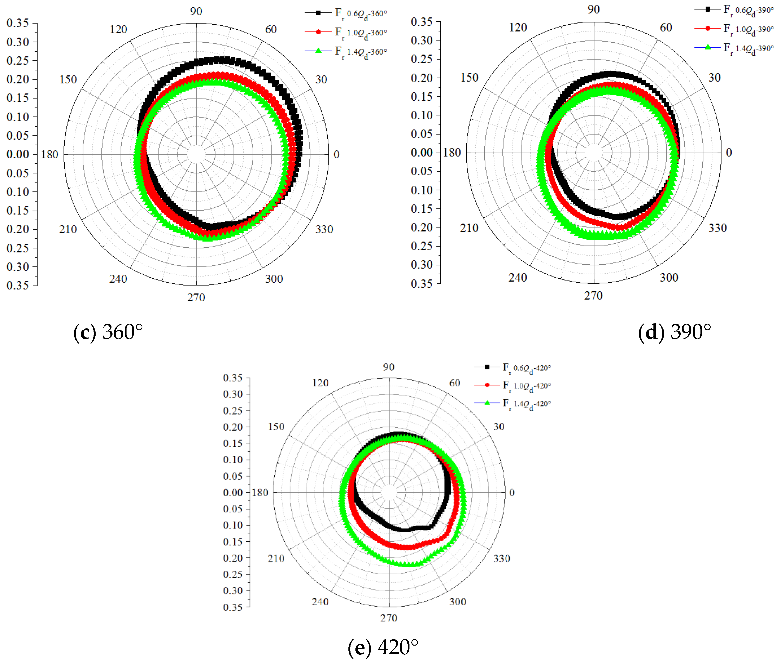
Figure 12 shows the radial force Fr curve of the impeller with different blade wrap angles when the impeller rotates. The calculation results are adopted the dimensionless coefficient CF.
C F = 2 F ρ u 2   2 D 2 b 2
where CF is the dimensionless coefficient of the force, F is the radial force, ρ is the density, u2 is the circumferential velocity of the impeller outlet, D2 is the impeller outer diameter, b2 is the impeller outlet width.
It can be seen from the figure, when the blade wrap angle is less than 360°, the radial force is significantly greater than that of the impeller with other wrap angles. Under low flow conditions, the radial force of the impeller significantly decreases continuously with the increase of the blade wrap angle.
Figure 13 and Figure 14 show the vector and pressure contour of the single blade centrifugal pump with different wrap angles. It can be seen from the vector diagram that the flow field is disturbed when the single blade centrifugal pump is working under part-loading conditions, there is a sudden change in the streamline, and there is an obvious low-speed vortex area in the impeller which means flow separation occurred. When the wrap angle of the impeller blade is increased, the flow field inside the pump is improved. From the pressure contour, it can be found that, with the increase of the wrap angle, the pressure distribution in the circular direction becomes relatively uniform. Therefore, increasing the wrap angle of the blade is a useful way to reduce the radial force under part-loading conditions. Under the designed flow rate condition or larger flow rate conditions, the radial force of the impeller also decreases with the increase of the wrap angle of the blade, and the effect is weakened when the wrap angle is larger than 360°.
Figure 15, Figure 16, Figure 17 and Figure 18 show the velocity vector and the pressure contour under the designed flow rate and larger flow rate conditions. Under these working conditions, the flow field in the pump is good, while for the impellers with 300° and 330° wrap angles, flow separation still happens. The pressure distribution in the circular direction is not axisymmetric, while the axisymmetric characteristic is improved when the wrap angle is increased. Comparing the performance of one impeller under different working conditions, it can be found that when the wrap angle is smaller than 360° the radial force decreases with the flow rate increase. When the wrap angle is 420°, the radial force is smaller under part-loading conditions, which increases with the flow rate increase. From the pressure cloud diagram of the pump with a blade wrap angle of 420°, it can be found that as the flow rate increases, a local low-pressure zone appears from the end of the spiral section of the volute to the outlet end, and the circumferential symmetry of the pressure distribution becomes worse resulting in an increase in the radial force.
The main cause of the radial force of the single blade centrifugal pump is the uneven circumferential pressure distribution in the pump. Figure 19 shows the circumferential pressure distribution at the outlet of the impeller of the single blade centrifugal pump under designed flow rate conditions. From the figure, it can be clearly seen that the axisymmetric characteristic is improved with the increase of the blade wrap angle, while uneven pressure distribution is always found at the volute outlet, impeller inlet and impeller outlet.

4. Conclusions

The effect of blade wrap angle on the performance of a single blade centrifugal pump is investigated based on unsteady numerical simulation. The external characteristics and radial force of single blade centrifugal pumps with five different wrap angles are simulated and analyzed. The research results are as follows:
(1)
Generally, the head and efficiency of the single-blade centrifugal pump are improved with the increase of blade wrap angle. With the increase of the blade wrap angle, the pump head tends to increase, and the H-Q curve becomes steeper, the pump efficiency increases gradually, but the high-efficiency area is narrowed. The P-Q curve becomes gentle with the increase of blade wrap angle.
(2)
The blade wrap angle has a significant impact on the radial force of the single blade centrifugal pump. When the blade wrap angle is less than 360°, the x component of the radial force is negative and the value is reduced with the increase of the wrap angle of the blade. When the wrap angle is larger than 360°, the x component of the radial force is positive and the value increases with the increase of the wrap angle. The y component of the impeller radial force has a maximum value when the wrap angle is 360° and 390°, and has a minimum value when the wrap angle is 300°.
(3)
Under part-loading conditions, the radial force of the single blade pump is significantly reduced with the increase of the blade wrap angle. When the wrap angle is smaller than 360°, the radial force decreases with the flow rate increase. In the condition that the wrap angle is larger than 360°, the radial force increases with the flow rate increase.
(4)
It suggested that the available blade wrap angle for single blade centrifugal pump should be between 360°and 420°, to achieve a better hydraulic performance and stable flow field.

Author Contributions

Data curation, L.T. and C.C.; Funding acquisition, W.S.; Investigation, Z.X.; Methodology, W.S.; Project administration, L.T.; Writing—original draft, L.T. and Y.Y. All authors have read and agreed to the published version of the manuscript.

Funding

This research was funded by the National Key Research and Development Project of China (no. 2019YFB 2005300), National High-Tech Ship Scientific Research Project of China (no. MIIT [2019] 360), the National Natural Science Foundation of China (No. 51979138), General project of natural science research in Colleges and universities of Jiangsu Province (No. 19KJB470029), and Jiangsu Water Conservancy Science and Technology Project (No. 2019038).

Conflicts of Interest

The authors declare no conflict of interest.

References

  1. Benra, F.K.; Dohmen, H.; Sommer, M. Periodically unsteady flow in a single-blade centrifugal pump: Numerical and experimental results. In Proceedings of the ASME 2005 Fluids Engineering Division Summer Meeting, Hoston, TX, USA, 19–23 June 2005; American Society of Mechanical Engineers: New York, NY, USA, 2005; pp. 1223–1231. [Google Scholar]
  2. Tang, S.; Yuan, S.; Zhu, Y. Convolutional Neural Network in Intelligent Fault Diagnosis toward Rotatory Machinery. IEEE Access 2020, 8, 86510–86519. [Google Scholar] [CrossRef]
  3. Stepanoff, A. Centrifugal and Axial Flow Pumps; Van Chong Book Company: New York, NY, USA, 1950. [Google Scholar]
  4. Biheller, H. Radial force on the impeller of centrifugal pumps with volute, semivolute, and fully concentric casings. J. Eng. Power 1965, 87, 319–322. [Google Scholar] [CrossRef]
  5. Chamieh, D.S.; Acosta, A.J.; Brennen, C.E.; Caughey, T.K. Experimental measurements of hydrodynamic radial forces and stiffness matrices for a centrifugal pump-impeller. J. Fluids Eng. 1985, 107, 307–315. [Google Scholar] [CrossRef] [Green Version]
  6. Adkins, D.R.; Brennen, C.E. Analyses of hydrodynamic radial forces on centrifugal pump impellers. ASME Trans. J. Fluids Eng. 1986, 110, 20–28. [Google Scholar] [CrossRef]
  7. Yun, H.; Brennen, C.E. Effect of Swirl on Rotordynamic Forces Caused by Front Shroud Pump Leakage. J. Fluids Eng. 2002, 124, 1005–1010. [Google Scholar]
  8. Brennen, C.E.; Acosta, A. Fluid-induced rotordynamic forces and instabilities. Struct. Control Health Monit. 2006, 13, 10–26. [Google Scholar] [CrossRef] [Green Version]
  9. Guelich, J.; Jud, W.; Hughes, S.F. Review of Parameters Influencing Hydraulic Forces on Centrifugal Impellers. Proc. Inst. Mech. Eng. Part A J. Power Energy 1987, 201, 163–174. [Google Scholar] [CrossRef]
  10. Boehning, F.; Timms, D.L.; Amaral, F.; Oliveira, L.; Graefe, R.; Hsu, P.L.; Schmitz-Rode, T.; Steinseifer, U. Evaluation of Hydraulic Radial Forces on the Impeller by the Volute in a Centrifugal Rotary Blood Pump. Artif. Organs 2011, 35, 818–825. [Google Scholar] [CrossRef] [PubMed]
  11. Alemi, H.; Ahmad Nourbakhsh, S.; Raisee, M.; Farhad Najafi, A. Development of new “multivolute casing” geometries for radial force reduction in centrifugal pumps. Eng. Appl. Comput. Fluid Mech. 2015, 9, 1–11. [Google Scholar] [CrossRef]
  12. Benra, F.K.; Dohmen, H.J.; Schneider, O. Calculation of hydrodynamic forces and flow induced vibrations of centrifugal sewage water pumps. In Proceedings of the ASME/JSME 2003 4th Joint Fluids Summer Engineering Conference, Honolulu, HI, USA, 6–10 July 2003; American Society of Mechanical Engineers: Hoston, TX, USA, 2003; pp. 603–608. [Google Scholar]
  13. Benra, F.K.; Dohmen, H.J.; Schneider, O. Measurement of flow induced rotor oscillations in a single-blade centrifugal pump. In Proceedings of the ASME/JSME 2004 Pressure Vessels and Piping Conference, San Diego, CA, USA, 25–29 July 2004; American Society of Mechanical Engineers: Hoston, TX, USA, 2004; pp. 167–174. [Google Scholar]
  14. Benra, F.K. Experimental investigation of hydrodynamic forces for different configurations of single-blade centrifugal pumps. In Proceedings of the 11th International Symposium on Transport Phenomena and Dynamics of Rotating Machinery (ISROMAC-11), Honolulu, HI, USA, 26 February–2 March 2006. [Google Scholar]
  15. Benra, F.K. Numerical and Experimental Investigation on the Flow Induced Oscillations of a Single-Blade Pump Impeller. J. Fluids Eng. 2006, 128, 783–793. [Google Scholar] [CrossRef]
  16. Aoki, M. Instantaneous Interblade Pressure Distributions and Fluctuating Radial Thrust in a Single-blade Centrifugal Pump. Bull. JSME 2008, 27, 2413–2420. [Google Scholar] [CrossRef]
  17. Nishi, Y.; Fujiwara, R.; Fukutomi, J. Design Method for Single-Blade Centrifugal Pump Impeller. J. Fluid Sci. Technol. 2009, 4, 786–800. [Google Scholar] [CrossRef] [Green Version]
  18. Nishi, Y.; Fukutomi, J.; Fujiwara, R. Radial Thrust of Single-Blade Centrifugal Pump. IJFMS 2011, 4, 387–395. [Google Scholar] [CrossRef] [Green Version]
  19. Nishi, Y.; Fukutomi, J. Effect of Blade Outlet Angle on Unsteady Hydrodynamic Force of Closed-Type Centrifugal Pump with Single Blade. Int. J. Rotating Mach. 2014, 2014, 1–16. [Google Scholar] [CrossRef] [Green Version]
  20. Tan, M.; Ji, Y.; Liu, H. Effect of Blade Wrap Angle on Performance of a Single-Channel Pump. Exp. Tech. 2018, 2018, 481–490. [Google Scholar] [CrossRef]
  21. Chen, J.; Shi, W.; Zhang, D. Influence of blade inlet angle on the performance of a single blade centrifugal pump. Eng. Appl. Comput. Fluid Mech. 2021, 15, 462–475. [Google Scholar]
  22. Tan, L.; Shi, W.; Zhang, D.; Zhou, L.; Wang, C. Numerical and experimental investigations of pressure fluctuations in single-channel pumps. Proc. Inst. Mech. Eng. Part A J. Power Energy 2018, 232, 97–415. [Google Scholar] [CrossRef]
  23. Jiang, Z.; Li, H.; Shi, G.; Liu, X. Flow Characteristics and Energy Loss within the Static Impeller of Multiphase Pump. Processes 2021, 9, 1025. [Google Scholar] [CrossRef]
  24. Yang, Y.; Zhou, L.; Shi, W.; He, Z.; Han, Y.; Xiao, Y. Interstage difference of pressure pulsation in a three-stage electrical submersible pump. J. Pet. Sci. Eng. 2020, 196, 107653. [Google Scholar] [CrossRef]
  25. Yang, Y.; Zhou, L.; Hang, J.; Du, D.; Shi, W.; He, Z. Energy characteristics and optimal design of diffuser meridian in an electrical submersible pump. Renew. Energy 2021, 167, 718–727. [Google Scholar] [CrossRef]
  26. Peng, G.; Huang, X.; Zhou, L.; Zhou, G.; Zhou, H. Solid-liquid two-phase flow and wear analysis in a large-scale centrifugal slurry pump. Eng. Fail. Anal. 2020, 114, 104602. [Google Scholar] [CrossRef]
  27. Li, X.; Jiang, Z.; Zhu, Z.; Si, Q.; Li, Y. Entropy generation analysis for the cavitating head-drop characteristic of a centrifugal pump. Proc. Inst. Mech. Eng. Part C J. Mech. Eng. Sci. 2018, 232, 4637–4646. [Google Scholar] [CrossRef]
  28. Tan, L.; Shi, W.; Zhang, D.; Wang, C.; Zhou, L.; Mahmoud, E. Numerical and experimental investigations on the hydrodynamic radial force of single-channel pumps. J. Mech. Sci. Technol. 2018, 32, 4571–4581. [Google Scholar] [CrossRef]
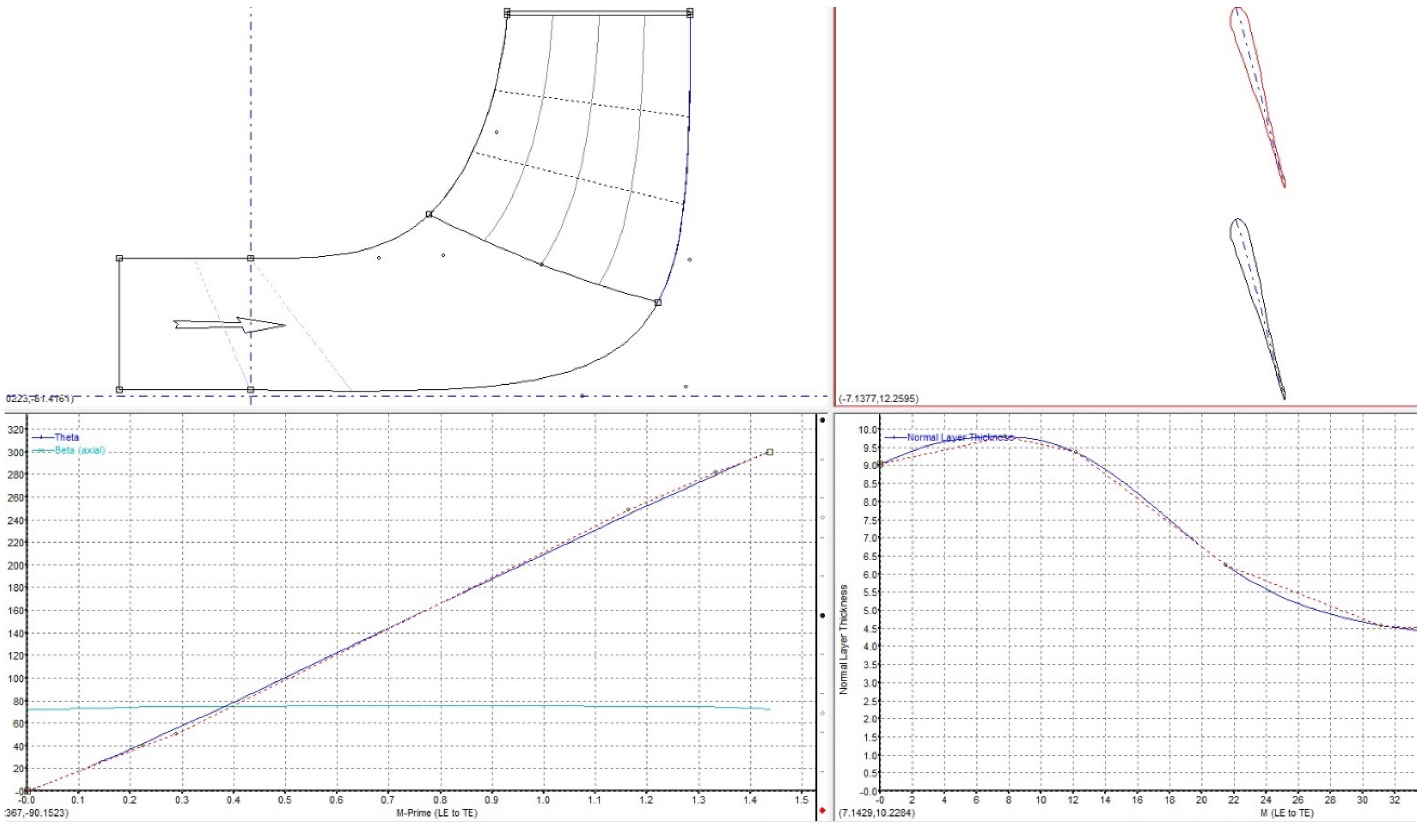
Figure 1. Design process of single blade centrifugal impeller by Bladegen.
Applsci 11 09052 g001
Figure 2. Mesh of different impellers.
Applsci 11 09052 g002
Figure 3. Experimental device: (1) valve in the outlet, (2) flowmeter, (3) valve in the inlet, (4) pressure transducer in the outlet, (5) pressure transducer in the inlet, (6) pump.
Applsci 11 09052 g003
Figure 4. Pressure sensors distribution.
Applsci 11 09052 g004
Figure 5. Pump performance.
Applsci 11 09052 g005
Figure 6. Comparison of pressure distribution in model 1 at design flowrate.
Applsci 11 09052 g006aApplsci 11 09052 g006b
Figure 7. External characteristics of single blade centrifugal pump with different wrap angles.
Applsci 11 09052 g007
Figure 8. Turbulence dissipation rate of single blade centrifugal pump with different wrap angle.
Applsci 11 09052 g008aApplsci 11 09052 g008b
Figure 9. Energy loess of single blade centrifugal pump with different wrap angles.
Applsci 11 09052 g009
Figure 10. Coordinate diagram of force.
Applsci 11 09052 g010
Figure 11. Radial force of a single centrifugal impeller with different wrap angles under the designed flow rate condition.
Applsci 11 09052 g011aApplsci 11 09052 g011b
Figure 12. Radial forces of the impellers with different blade wrap angles according to the rotation of the impeller.
Applsci 11 09052 g012aApplsci 11 09052 g012b
Figure 13. Velocity vector of the pump under part-loading conditions (0.6 Qd).
Applsci 11 09052 g013
Figure 14. Pressure distribution in the pump under part-loading conditions (0.6 Qd).
Applsci 11 09052 g014
Figure 15. Velocity vector of the pump under the designed flow rate condition.
Applsci 11 09052 g015
Figure 16. Velocity vector of the pump large flow rate condition (1.4 Qd).
Applsci 11 09052 g016
Figure 17. Pressure distribution in the pump under designed flow rate conditions.
Applsci 11 09052 g017
Figure 18. Pressure distribution in the pump under large flow rate conditions (1.4 Qd).
Applsci 11 09052 g018
Figure 19. Pressure distribution at the impeller outlet under designed flow rate condition.
Applsci 11 09052 g019
Table 1. Main geometric parameters of the pump.
Main ParametersValue
Inlet diameter of impeller, Dj (mm)45
Outlet diameter of impeller, D2 (mm)125
Outlet width of impeller, b2 (mm)30
Blade wrap angle, φ (°)360
Inlet diameter of volute, D3 (mm)135
Inlet width of volute, b3 (mm)46
Blade outlet angle, β2 (°)18
Publisher’s Note: MDPI stays neutral with regard to jurisdictional claims in published maps and institutional affiliations.