Article

Undrained Stability Analysis of Shallow Tunnel and Sinkhole in Soft Clay: The Cavity Contraction Method

1
School of Qilu Transportation, Shandong University, Jinan 250002, China
2
Shandong High-Speed Group Co., Ltd., Engineering Management Department, Jinan 250098, China
3
Shandong High-Speed Lanlin High-Speed Group Co., Ltd., Linyi 276713, China
4
Shandong Provincial Communications Planning and Design Institute Co., Ltd., Jinan 250031, China
*
Authors to whom correspondence should be addressed.
Appl. Sci. 2021, 11(19), 9059; https://doi.org/10.3390/app11199059
Submission received: 8 August 2021 / Revised: 16 September 2021 / Accepted: 20 September 2021 / Published: 28 September 2021
(This article belongs to the Section Civil Engineering)

Abstract

:
This paper presents theoretical methods for the undrained stability analysis of shallow tunnels/sinkholes in clay based on the cavity contraction theory, with some assumptions and simplifications. To examine the accuracy and reliability of the new methods, a database was assembled, which consists of stability numbers of tunnel/sinkholes in clays from 22 centrifuge model tests, 10 field tests, and 62 FELA results. It is shown that the proposed methods give an average of 2.5% overestimation for the stability numbers from model tests and is in a good agreement with the FELA results. The cavity contraction theory-based methods are then discussed, which could provide useful guidance for designers to roughly assess shallow tunnel/sinkhole stability in clays.

1. Introduction

Ground stability is one of the two major concerns for geotechnical engineering practices, which require that the ground soil mass remains stable under the given or expected loading conditions. This paper focuses on the stability analysis of two typical underground openings (i.e., shield tunnels and sinkholes), aiming to present simple methods for the safety assessment during their design and construction.
In order to maintain the stability during shield tunnelling in clays, temporary supports provided by compressed air or slurry [1,2] are usually necessary. For shield tunnelling in clay, the construction process is usually sufficiently rapid that the clay behaviour around the heading is often regarded as undrained [3,4]. Since the failure mechanism of a tunnel may be similar to that of a sinkhole, sinkhole stability is also considered in this paper.
Many studies have investigated the undrained stability of shallow tunnels and sinkholes by model tests [5,6], the limit analysis method [1,7,8,9,10,11,12,13,14,15], and the displacement finite element/difference method [16,17]. To investigate the influence of embedment ratio and tunnel heading geometry on tunnel stability, Mair [5] conducted two series of 2D/3D centrifuge model tests in clays, and found that the tunnel heading stability was strongly affected by the tunnel heading geometry. Following Mair [5], Wu and Lee [6] studied the tunnelling-induced ground movement and collapse mechanisms of single and parallel tunnels, and obtained a series of stability results. Davis, et al. [1] assessed the stability of shallow tunnels using the lower and upper bound theory under plane strain conditions. Afterwards, many attempts have been made to derive the upper bound (UB) solutions for 2D/3D tunnel stability, with various kinematically admissible velocity fields [11,12,13,16,18,19]. Sloan [20,21] developed the finite element limit analysis (FELA) method by linear programming, which made it possible to conduct geotechnical stability analysis without predefining a failure mode. Using the FELA method, the undrained stability of tunnels under plane strain conditions can be easily determined, even taking the variation of the undrained shear strength into consideration [7,8,22]. Later, Augarde, et al. [9], Wilson, et al. [10] and Wilson [23] revisited these problems using more advanced FELA techniques and smaller gaps between results obtained, and the lower bound and the upper bound methods were derived. Furthermore, the undrained face stability in clay was also analyzed by the finite element method (e.g., Ukritchon, et al. [17], Huang, et al. [12], Huang, et al. [16]), which provided a valuable benchmark for tunnel stability analysis.
Apart from the abovementioned methods of stability analysis for tunnels/sinkholes, cavity contraction theory—which is a simple and powerful tool—has also been widely applied in tunnel deformation and stability analysis [3,24,25,26,27,28,29,30]. For tunnel stability in undrained clay, Yu [25] proposed a simple equation based on cavity contraction theory in Tresca materials. However, this equation failed to consider the influence of finite cover depth on tunnel stability, which could overestimate the stability for a shallow tunnel. In addition, there is no equation, to the best knowledge of the authors, that can be directly used to account for the stability of a tunnel heading. To fill these gaps, this paper mainly extends the work of Yu [25] and modifies Yu’s equation by developing the cavity contraction theory in a finite Tresca soil mass. Then, a simple equation that could predict the tunnel/sinkhole stability is proposed based on the newly developed cavity contraction solution, and validated after comparison with published results.

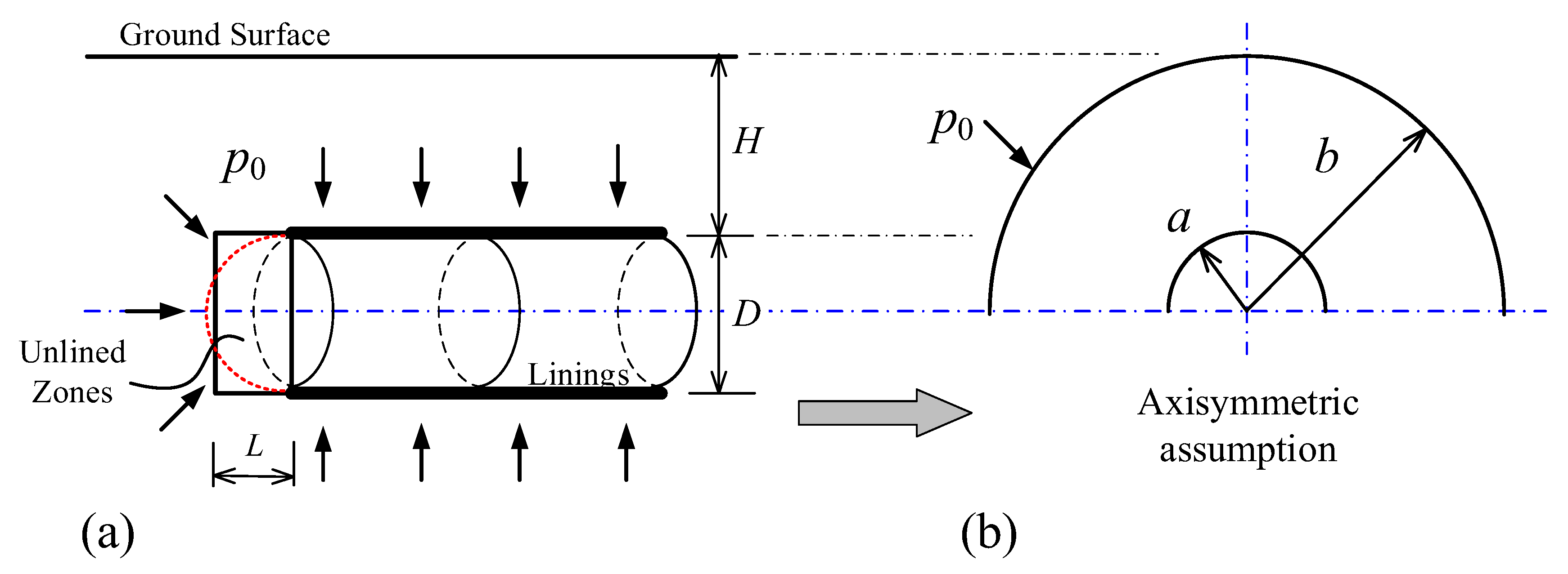
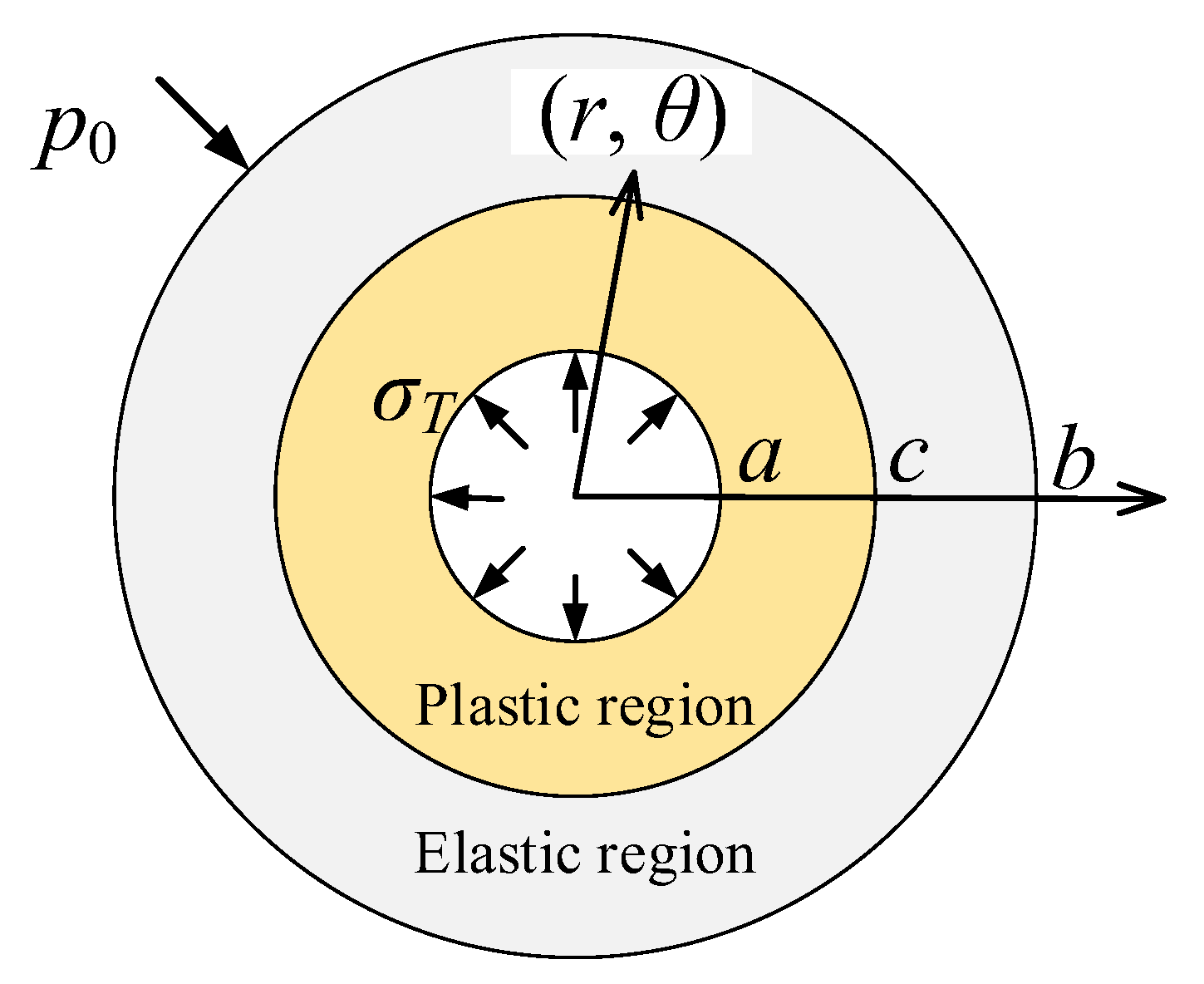
2. Problem Definition

It is necessary to make some assumptions and simplifications to investigate the stability of a shallow tunnel/sinkhole. This paper mainly takes the tunnel collapse as an example in the theoretical analysis and then extends this similar method to the sinkhole stability analysis. As schematically shown in Figure 1a [24], a circular traffic tunnel with a diameter of D is excavated by a tunnel shield, and the vertical distance from the ground surface to the mid-crown of the tunnel is denoted as H. The rigid, permanent linings are installed behind the tunnel face and an unlined zone is usually left with a length of L. A temporary supporting pressure σ T is required in the unlined zone and there is a uniform surcharge σ S acting on the ground surface, which could accelerate the tunnel collapse process. The soft clay around the tunnel is assumed to be isotropic and homogenous with a unit weight of γ. For convenience, the soft clay is modelled by the linear elastic-perfectly plastic Tresca material to develop the analytical solution, which is a commonly used, simplified constitutive model for soft clay in undrained conditions. It is worthwhile to remark here that the undrained shear strength usually varies with depth, depending on the clay type and site history [31]. There are, however, a large number of cases in which this simplified assumption is adequate to make preliminarily predictions of the tunnel stability [4,32]. Besides, this paper does not aim to investigate the improved or deteriorated tunnel stability with time. For heavily over-consolidated clay, the dissipation of the pore water pressure, which may affect the tunnel stability, is not considered here. For a shallow sinkhole, it is assumed the shape of the sinkhole is a standard sphere with a soil cover of H and diameter of D, and the collapse behaviour of the sinkhole is modelled by the spherical cavity contraction model.
Following Mair and Taylor [3], the excavation of a circular tunnel could be well modelled by the contraction of a cylindrical or spherical cavity if the axisymmetric assumption is adopted, as shown in Figure 1b. It is assumed that the tunnel excavation is simulated by slowly reducing the internal cavity pressure from p 0 ( p 0 = σ S + γ H + D / 2 ) to σ T , and the inner and outer radii of the cavity are a = D / 2 and b = H + D / 2 , respectively. In reality, the in situ stress state is normally non-hydrostatic and the axisymmetric assumption is not strictly correct, but previous studies have shown the simple concept of cavity contraction could predict tunnel stability and ground deformation [3,25,26,27]. Therefore, the assumptions of Mair and Taylor [3] are still followed and the induced error will be discussed.
To assess the stability of a tunnel heading/sinkhole, the stability number N defined by Broms and Bennermark [33] is adopted here, which is expressed as:
N = σ S + γ H + D / 2 σ T s u = p 0 σ T s u
where s u is the undrained shear strength of soft clay. The derivation of N by the cavity contraction theory will be shown in the following section.

3. Theoretical Analysis

Initially, the hydrostatic in situ stress ( p 0 ) acts throughout soil mass around the tunnel/sinkhole. Then, with the tunnel excavation, the internal supporting pressure gradually decreases from p 0 to σ T , and a plastic zone forms with an outer radius of c as shown in Figure 2. Under the axisymmetric conditions, the polar cylindrical coordinates (r, θ, z) or the polar spherical coordinates (r, θ, Φ) are adopted to account for particle position. Taking compression as positive, the stress boundary conditions of the cavity contraction problem are therefore defined as:
σ r r = b = p 0
σ r r = a = σ T
σ r r = c = σ c
where σ r is the radial stress component; r is the position of a soil particle; c denotes the radius of the elastic-plastic boundary; σ c is the radial stress at the elastic-plastic boundary.
The stress components should be in equilibrium in the radial direction, which can be written as:
d σ r d r + k r σ r σ θ = 0
where σ θ is the circumferential stress; k is defined as the shape factor and k = 1 for the cylindrical cavity and k = 2 for the spherical cavity.
As shown in Figure 2, in the plastic region (a < r < c), the soil behaves in an elastic-plastic manner. In the unloading process, σ r is the minor principal stress while σ θ becomes the major principal stress. For soft clay in undrained conditions, the Tresca yielding function can be expressed as:
σ θ σ r = 2 s u
Combining Equations (5) and (6), the spatial derivative of the radial stress can be derived as:
d σ r d r = 2 k s u r
Integrating Equation (7) over the interval [a, c], the internal supporting pressure that is the function of the elastic-plastic boundary can be written as:
σ T = σ c 2 k s u ln c / a
In the elastic region (c < r < b), only elastic deformation occurs and the stress-strain relationship obeys Hook’s law:
ε r = d u d r = 1 v 2 2 k E σ r k v 1 v 2 k σ θ
ε θ = u r = 1 v 2 2 k E v 1 v 2 k σ r + 1 + v k v σ θ
where ε r and ε θ are the radial and circumferential strains, respectively; u is the displacement of a soil particle and is purely in the radial direction; E and v are the elastic modulus and Poisson’s ratio, respectively. Combining Equations (2), (4), (5), (9) and (10), the stress components in the elastic region can be obtained as:
σ r = p 0 + σ c p 0 b / c k + 1 1 b / r k + 1 1
σ θ = p 0 σ c p 0 b / c k + 1 1 1 k b / r k + 1 1
At the elastic–plastic boundary (i.e., r = c), the stress components should also satisfy the yielding function (Equation (8)). Therefore, substituting Equations (11) and (12) into Equation (6), we can get:
p 0 σ c = 2 k s u k + 1 1 c b k + 1
Combining Equations (8) and (13), the relationship between the internal supporting pressure and the radius of the elastic-plastic boundary can be derived as:
p 0 σ T = 2 k s u ln c a + 2 k s u k + 1 1 c b k + 1
It is worthwhile to note that the abovementioned analysis is conducted regarding the finite thickness of the cavity wall (named finite solution and hereafter). The tunnel is constructed, however, in semi-infinite space and the soil mass in the side and downward directions is infinite. Thus, it is also necessary to present the cavity contraction solution for an infinite soil mass (named infinite solution and hereafter). Following the similar procedure for a finite soil mass, the solution for an infinite soil mass [25] can be easily obtained by setting b = ∞:
p 0 σ T = 2 k s u ln c a + 2 k s u k + 1
Caquot and Kerisel [34] suggested the tunnel would be in an unsafe state once the plastic zone expands to the ground surface (i.e., c = b = H + D/2). Then, taking this criterion, the stability number for a shallow tunnel can be derived by the cavity contraction method, as:
N = p 0 σ T s u = 2 k ln 2 H D + 1   ( finite   solution )
N = p 0 σ T s u = 2 k ln 2 H D + 1   ( infinite   solution )
The mean value of the stability numbers calculated by Equations (16) and (17) is:
N = 2 k ln 2 H D + 1 + k k + 1
It is interesting that, when k = 1 , Equation (16) is identical to that derived by [35] from the collapse analysis of a plane strain soil wedge and the lower bound solution (LB) given by Davis, et al. [1] for plane strain circular tunnel. When k = 2 , it recovers the lower bound solutions for circular tunnel heading and for sinkhole collapse that were proposed by Davis, et al. [1] and Augarde, et al. [9], respectively. It is shown that an additional constant term always appears in Equation (17) compared to Equation (16), which indicates that the finite solution always predicts a smaller stability number than that by the infinite solution at the same embedment ratio. The accuracy of the above expressions for tunnel stability analysis will be discussed and validated in the following section.

4. Validation and Discussion

This section mainly shows how the simple cavity contraction method could reasonably predict the undrained stability of a shallow tunnel. The stability number predicted by this simple method is compared with those derived from centrifuge model tests, in situ tests and numerical simulations, and some limitations of the method are also discussed.

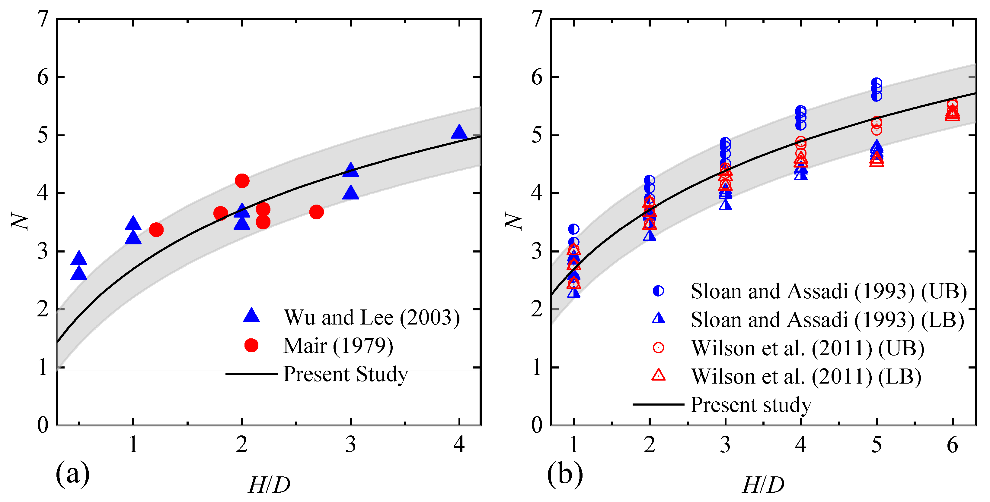
4.1. D Tunnel Stability Analysis

Firstly, predictions of plane–strain (2D, L / D ) tunnel stability made by cylindrical cavity contraction solutions (k = 1) are compared with those experimental results of Mair [5] and Wu and Lee [6], as shown in Figure 3a. The figure shows that the experimental results are well contained within the predictions of finite solution (Equation (16)) and infinite solution (Equation (17)). These two analytical solutions are also compared with typical stability numbers computed from lower and upper bound limit analyses (see Figure 3b).
It is shown that the plane–strain stability numbers calculated by Sloan and Assadi [8] and Wilson, et al. [10], for tunnels with soil and geometry parameters γ D / s u [ 0 , 3 ] and H / D [ 1 , 6 ] are also satisfactorily bracketed by the infinite and finite cavity contraction solutions which locate close to the UB and LB, respectively. It can also be seen, from Figure 3, that the mean values of the stability numbers calculated by finite and infinite solutions are in good agreement with the experimental and simulated (FELA) data, and thus, Equation (18) is recommended here to predict the 2D tunnel stability.

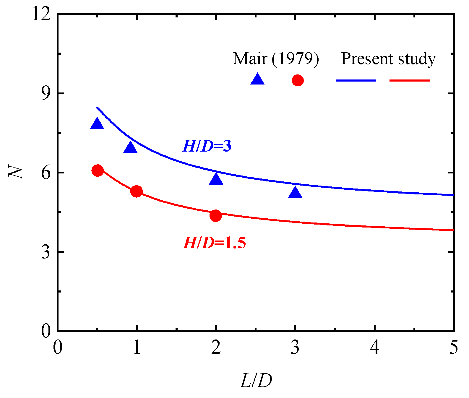
4.2. D Tunnel Stability Analysis: L/D ≥ 0.5

4.2.1. Assumptions and Theory

In 3D conditions, the tunnel stability would be affected by the tunnel face and then the stability number is relevant to L/D. The 3D tunnel behaviour would roughly lie within the contraction of a spherical cavity and a cylindrical cavity. For simplification, we assume that:
(a)
Equation (18) still holds in 3D conditions, but the shape factor k varies with L/D. Although the collapse mechanism for a tunnel heading is much more complicated than that for a 2D tunnel, Equation (18) is still adopted for 3D tunnel stability analysis because of its simplification, clearness and sound theoretical basis.
(b)
The tunnel heading stability is exactly modelled by a spherical cavity contraction (k = 2) when L/D = 0.5. With L/D increasing from 0.5 to ∞, the tunnel collapse model would change from a spherical cavity to a cylindrical cavity and the shape factor would decrease from 2 to 1.
(c)
The shape factor with L/D is determined following Liang [36], who investigated the ellipsoidal cavity expansion problem and presented a similar expression of k with the length-to-width ratio of a rectangular (i.e., L/D in the present paper) by the conformal mapping method. The relationship between k and L/D can be written as:
k = 2 L / D 0.5 L / D + 0.5 , L / D 0.5
and we chose this relationship mainly because there is only this equation available in the literature without losing simplification. Under the above assumptions, the 3D tunnel stability ( L / D 0.5 ) can then be assessed by substituting Equation (19) into Equation (18).

4.2.2. Comparison of Predicted Stability Numbers with Centrifuge Model Tests Results

Figure 4 shows the comparison of stability numbers with various L/D derived from cavity contraction solution (Equations (18) and (19)) and centrifuge model tests of Mair [5]. The model tests were conducted in 3D semi-circular apparatus (Main Series II in [5]) at an average acceleration of 118g. The tunnel excavation was modelled by gradually reducing the internal supporting pressure, which was provided by an airbag was recorded during the whole unloading process. The saturated Speswhite clay is used in the tests of Main Series II, and the undrained shear strength is kept constant in this series. It can be seen again the predicted (Equation (18)) and measured values (model tests of Mair [5]) match well with each other, which shows the reasonability of the cavity contraction method in predicting 3D tunnel stability.

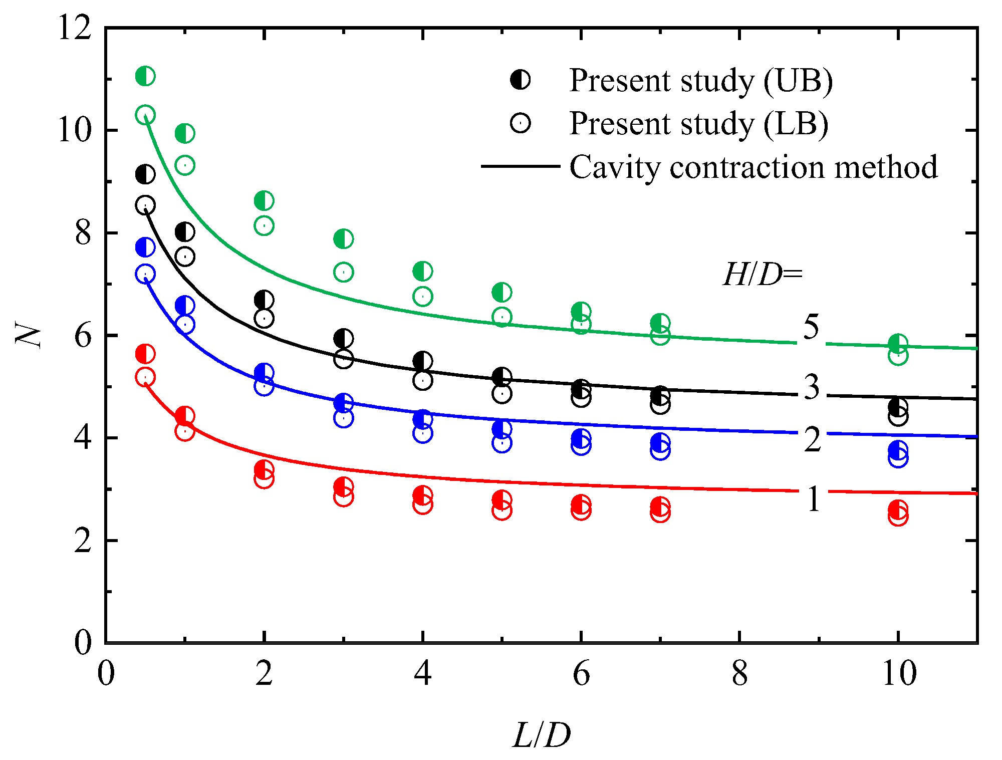
4.2.3. Comparison of Predicted Stability Numbers with FELA Results

In order to enlarge the database and further demonstrate the reliability of cavity contraction theory in the prediction of the tunnel heading stability, a new series of 3D numerical simulations are conducted in this paper, with the aid of the FELA software Optum G3. The influence of L/D and H/D on the stability number is focused in this series, which is an extension of Sloan [37] for 3D tunnel stability. In the numerical model, the vertical displacement of the bottom, and the horizontal displacement of the two sides are restricted. The minimum distances from the tunnel centre to the bottom and right/left sides are large enough to eliminate the influence of the possible boundary effect. In the lined zone, the linings are modelled by a smooth, rigid element, and in the unlined zone the supporting pressure σ T is optimized in the LB and UB limit analysis. The soil is set as the weightless Tresca material, and default material parameters are adopted since these parameters are believed not to affect the undrained tunnel stability [9]. Adaptative meshes are applied in calculation and the initial and final mesh numbers are 1000 and 10,000, respectively. It has been pre-tested that the mesh densities can satisfy the calculation accuracy.
Figure 5 shows the tunnel stability number calculated by Optum G3 and the cavity contraction method (Equation (18)). It is shown that the theoretical results derived by Equation (18) agree well with numerical results when H/D ≤ 3 but underestimate the tunnel stability when H/D = 5. It means the tunnel may not collapse when the plastic zone expands to the ground surface because of the arching effect, and some errors may also be induced from the simplified definition of k, as shown in Equation (19).

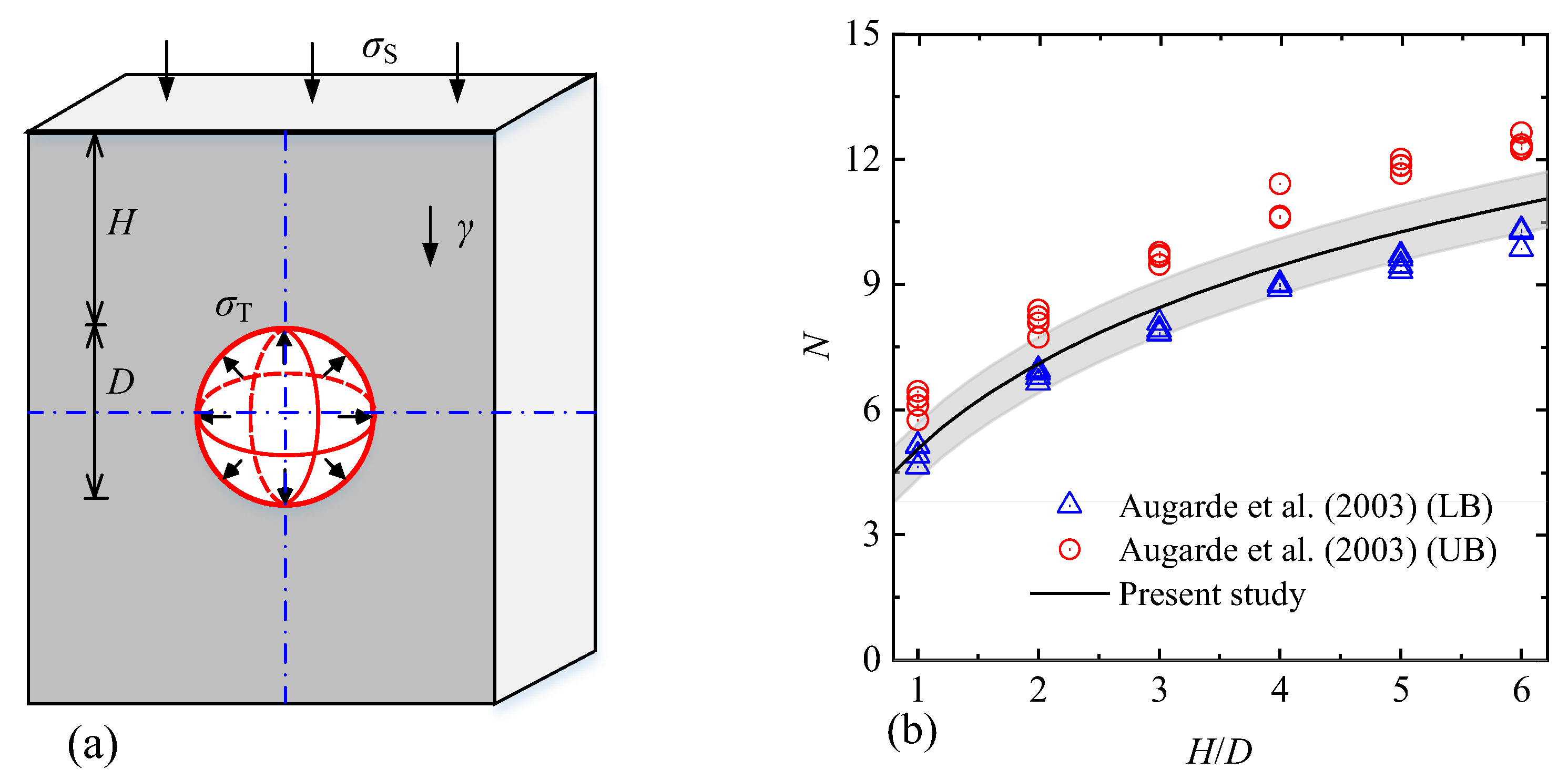
4.3. Sinkhole Stability Analysis

Augarde, et al. [15] investigated the undrained stability of a shallow sinkhole by the FELA method, where the sinkhole was idealized as a sphere (cover depth is H and the diameter is D), as shown in Figure 6a. The soil was assumed to be homogenous and uniform with γ D / s u [0, 3]. Similarly, to predict the sinkhole stability, the spherical cavity contraction solution (k = 2) is applied and the predicted and simulated (FELA) stability numbers are depicted in Figure 6b. Predictions by the spherical cavity solution are in reasonable agreement with the upper and lower bound results of Augarde, et al. [15].

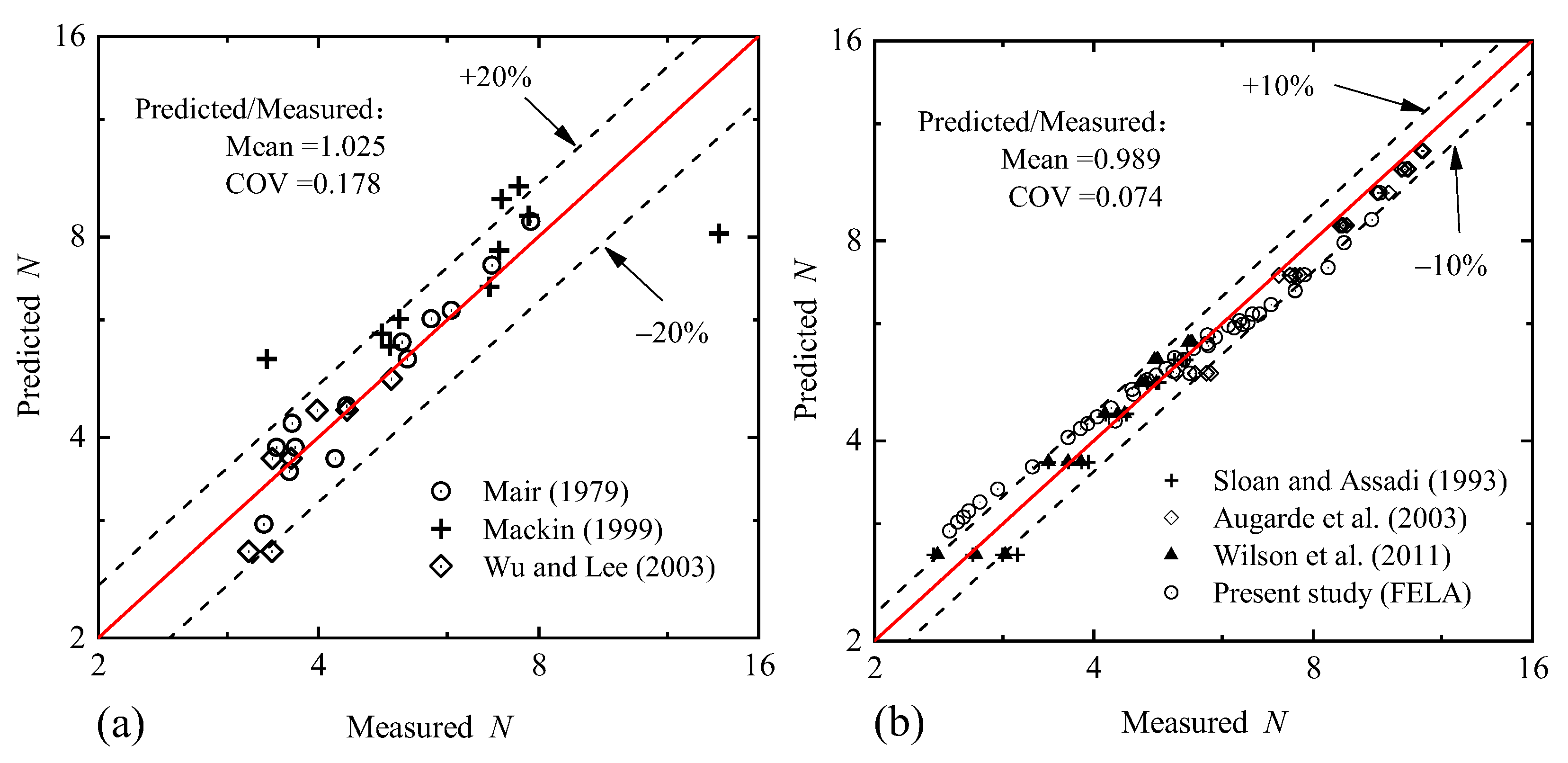
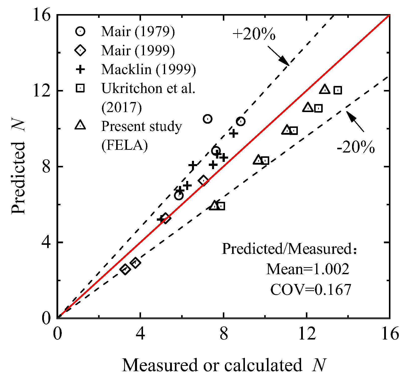
4.4. Database Establishment and Error Analysis

To thoroughly and quantitively assess the reliability of the proposed method, a database consisting of 22 centrifuge model tests, 10 field tests, and 62 FELA results on the shallow tunnel stability in clays is assembled as shown in Table 1. It needs to be noted that only the results satisfying H/D < 6 and L/D ≥ 0.5 are selected to meet the requirement of shallow tunnels. The original references of in situ results were not easily available but were summarised in Macklin [32]. For FELA results, only the average values of lower and upper bounds are recorded.
Stability numbers calculated by cavity contraction solutions (Equations (18) and (19)) are plotted versus those measured (tests in the field/laboratory) and simulated results (FELA), as shown in Figure 7 on a logarithmic scale. Figure 7a shown that the cavity contraction method gives a mean of 2.5% overestimation of the stability number than that measured in the field/laboratory. The coefficient of variation (COV) is 0.178, which is mainly caused by the scatter of field test results [32]. This may be caused by the uncertainty of complex geological conditions, stress history, measuring error and so on. In Figure 7b, when comparing with simulated stability numbers calculated by the FELA method, the cavity contraction solutions give a very good estimation of tunnel stability with the COV = 7.4%, which indicates the reliability of cavity contraction in predicting the tunnel heading stability. However, cavity contraction solutions seem to overestimate the tunnel stability at a lower N (usually for shallow tunnels) but underestimate the tunnel stability at a higher N. The overpredictions are mainly because the term of (H + 0.5D) in Equation (1) results in a higher N for very shallow tunnels. On the other hand, the cavity contraction method is developed under the framework of static analysis and thus tends to give lower bound results for tunnel stability, which is why the underestimation is observed for a larger N. Furthermore, the abovementioned reasons such as the simplified definition of k, the definition of the tunnel collapse, and the axisymmetric assumption, also play a role in the prediction accuracy of tunnel stability.
Although many factors seem to put a limit on the power of the cavity contraction method, the comparison with measured/simulated results indicates this simple method can still give a rather accurate prediction of tunnel stability in clays.

4.5. 3D Tunnel Stability Analysis: 0 ≤ L/D ≤ 0.5

In the case of L/D < 0.5, Equation (18) is still adopted here but the shape factor k needs to be re-defined. It is assumed k decreases linearly with L/D and k = k0 at L/D = 0 (i.e., tunnel face). Therefore, the shape factor k for L / D [0, 0.5] can be written as:
k = 4 2 k 0 L / D + k 0 , 0 L / D < 0.5
The factor k 0 should be determined by the least-squares method, with the database listed in Table 2.
It should be noted that many studies have focused on tunnel face stability by numerical simulations. However, most of them only gave the upper bound results or conducted calculations in plane strain conditions, which rendered the “real” stability number unavailable and these results are excluded.
To determine k 0 , an error function f is defined as:
f = i = 1 m N pre N 0 2
where N 0 is the stability number in the database (Table 2) and N pre is the predicted N by Equations (18) and (20); m is the total number of the data in Table 2. The derivation of the error function is:
f k 0 = 2 i = 1 m N pre N T 0 2 ln 2 H D + 1 + 1 k 0 + 1 2
and k 0 should be the root of Equation (22) and can be calculated as k 0 = 2.36 after substituting the data in Table 2 into Equation (22). Then the shape factor which is the function of L/D can be summarized as:
k = 2 L / D 0.5 L / D + 0.5 , L / D 0.5 2.36 0.72 L / D ,   0   L / D < 0.5
When 0 ≤ L/D < 0.5, the predicted versus measured (or calculated) stability number N is shown in Figure 8. It is found that the theoretical results agree well with the database in Table 2, which means k 0 = 2.36 is reasonable in the stability analysis of a tunnel face.

5. Conclusions

This paper investigated the undrained stability of shallow tunnels/sinkholes in clay. Simple methods for the prediction of tunnel/sinkhole stability were established based on the cavity contraction theory. The accuracy of the new methods was validated by comparing them with an assembled database consisting of 22 centrifuge model tests, 10 field tests, and 62 FELA results. It was found that the new methods give a 2.5% overestimation of the stability number when compared with model test results, and is in a very good agreement with the FELA results, which suggests that they can be used for the preliminary stability analysis of tunnels/sinkholes in clays.
Note that this paper focused on the short-term stability of tunnels/sinkholes in clays. Meanwhile, for the sake of simplicity in the analytical analysis, the soil ground was assumed to be homogeneous and isotropic. Consequently, the new methods may not be suitable for the analysis of tunnels/sinkholes in soils with a great depth-variation of strength.

Author Contributions

Conceptualization, H.Y. and X.S.; methodology, H.Q. and W.C.; software, W.C. and H.L.; validation, H.Q., J.C. and L.K.; formal analysis, X.W.; data curation, H.Q., X.S. and J.Z.; writing—original draft preparation, H.Q. and W.C.; writing—review and editing, G.Y.; supervision, X.S.; project administration, X.S. All authors have read and agreed to the published version of the manuscript.

Funding

This research received no external funding.

Institutional Review Board Statement

Not applicable.

Informed Consent Statement

Not applicable.

Data Availability Statement

Not applicable.

Conflicts of Interest

The authors declare no conflict of interest.

References

  1. Davis, E.; Gunn, M.; Mair, R.; Seneviratine, H. The stability of shallow tunnels and underground openings in cohesive material. Géotechnique 1980, 30, 397–416. [Google Scholar] [CrossRef]
  2. Anagnostou, G.; Kovári, K. The face stability of slurry-shield-driven tunnels. Tunn. Undergr. Space Technol. 1994, 9, 165–174. [Google Scholar] [CrossRef]
  3. Mair, R.J.; Taylor, R.N. Prediction of Clay around Tunnels Uing Plasticity Solutions. In Predictive Soil Mechanics, Proceedings of the Wroth Memorial Symposium, Oxford, UK, 27–29 July 1992; Thomas Telford: Oxford, UK, 1993; pp. 449–463. [Google Scholar]
  4. Mair, R.J.; Taylor, R.N. Theme lecture: Bored tunnelling in the urban environment. In Proceedings of the Fourteenth International Conference on Soil Mechanics and Foundation Engineering, Hamburg, Germany, 6–12 September 1997; Balkema: Rotterdam, The Netherland, 1999; pp. 2353–2385. [Google Scholar]
  5. Mair, R.J. Centrifugal Modelling of Tunnel Construction in Soft Clay; University of Cambridge: London, UK, 1979. [Google Scholar]
  6. Wu, B.; Lee, C. Ground movements and collapse mechanisms induced by tunneling in clayey soil. Int. J. Phys. Model. Geotech. 2003, 3, 15–29. [Google Scholar] [CrossRef]
  7. Sloan, S.; Assadi, A. Undrained stability of a square tunnel in a soil whose strength increases linearly with depth. Comput. Geotech. 1991, 12, 321–346. [Google Scholar] [CrossRef]
  8. Sloan, S.W.; Assadi, A. Stability of Shallow Tunnels in Soft Ground; Predictive soil mechanics. Proceeding of the Wroth Memorial Symposium, Oxford, UK, 27–29 July 1992; Thomas Telford: London, UK, 1993; pp. 644–663. [Google Scholar]
  9. Augarde, C.E.; Lyamin, A.V.; Sloan, S.W. Stability of an undrained plane strain heading revisited. Comput. Geotech. 2003, 30, 419–430. [Google Scholar] [CrossRef]
  10. Wilson, D.W.; Abbo, A.J.; Sloan, S.W.; Lyamin, A.V. Undrained stability of a circular tunnel where the shear strength increases linearly with depth. Can. Geotech. J. 2011, 48, 1328–1342. [Google Scholar] [CrossRef]
  11. Mollon, G.; Dias, D.; Soubra, A.H. Continuous velocity fields for collapse and blowout of a pressurized tunnel face in purely cohesive soil. Int. J. Numer. Anal. Methods Geomech. 2013, 37, 2061–2083. [Google Scholar] [CrossRef] [Green Version]
  12. Huang, M.; Li, S.; Yu, J.; Tan, J.Q.W. Continuous field based upper bound analysis for three-dimensional tunnel face stability in undrained clay. Comput. Geotech. 2018, 94, 207–213. [Google Scholar] [CrossRef]
  13. Osman, A.; Mair, R.; Bolton, M. On the kinematics of 2D tunnel collapse in undrained clay. Géotechnique 2006, 56, 585–595. [Google Scholar] [CrossRef] [Green Version]
  14. Keawsawasvong, S.; Ukritchon, B. Undrained basal stability of braced circular excavations in non-homogeneous clays with linear increase of strength with depth. Comput. Geotech. 2019, 115, 103180. [Google Scholar] [CrossRef]
  15. Augarde, C.E.; Lyamin, A.V.; Sloan, S.W. Prediction of undrained sinkhole collapse. J. Geotech. Geoenviron. Eng. 2003, 129, 197–205. [Google Scholar] [CrossRef] [Green Version]
  16. Huang, M.; Tang, Z.; Zhou, W.; Yuan, J. Upper bound solutions for face stability of circular tunnels in non-homogeneous and anisotropic clays. Comput. Geotech. 2018, 98, 189–196. [Google Scholar] [CrossRef]
  17. Ukritchon, B.; Yingchaloenkitkhajorn, K.; Keawsawasvong, S. Three-dimensional undrained tunnel face stability in clay with a linearly increasing shear strength with depth. Comput. Geotech. 2017, 88, 146–151. [Google Scholar] [CrossRef]
  18. Klar, A.; Osman, A.S.; Bolton, M. 2D and 3D upper bound solutions for tunnel excavation using ‘elastic’flow fields. Int. J. Numer. Anal. Methods Geomech. 2007, 31, 1367–1374. [Google Scholar] [CrossRef]
  19. Zhang, F.; Gao, Y.F.; Wu, Y.X.; Zhang, N. Upper-bound solutions for face stability of circular tunnels in undrained clays. Géotechnique 2017, 68, 76–85. [Google Scholar] [CrossRef]
  20. Sloan, S. Lower bound limit analysis using finite elements and linear programming. Int. J. Numer. Anal. Methods Geomech. 1988, 12, 61–77. [Google Scholar] [CrossRef]
  21. Sloan, S. Upper bound limit analysis using finite elements and linear programming. Int. J. Numer. Anal. Methods Geomech. 1989, 13, 263–282. [Google Scholar] [CrossRef]
  22. Sloan, S.; Assadi, A. Undrained stability of a plane strain heading. Can. Geotech. J. 1994, 31, 443–450. [Google Scholar] [CrossRef]
  23. Wilson, D.W.; Abbo, A.J.; Sloan, S.W.; Lyamin, A.V. Undrained stability of a square tunnel where the shear strength increases linearly with depth. Comput. Geotech. 2013, 49, 314–325. [Google Scholar] [CrossRef]
  24. Mair, R.J. Tunnelling and geotechnics: New horizons. Géotechnique 2008, 58, 695–736. [Google Scholar] [CrossRef] [Green Version]
  25. Yu, H.-S. Cavity Expansion Methods in Geomechanics; Kluwer Academic Publishers: Dordrecht, The Netherlands, 2000. [Google Scholar]
  26. Mo, P.-Q.; Yu, H.-S. Undrained Cavity-Contraction Analysis for Prediction of Soil Behavior around Tunnels. Int. J. Geomech. 2017, 17, 04016121. [Google Scholar] [CrossRef] [Green Version]
  27. Yu, H.-S.; Rowe, R.K. Plasticity solutions for soil behaviour around contracting cavities and tunnels. Int. J. Numer. Anal. Methods Geomech. 1999, 23, 1245–1279. [Google Scholar] [CrossRef]
  28. Xu, C.; Xia, C. A new large strain approach for predicting tunnel deformation in strain-softening rock mass based on the generalized Zhang-Zhu strength criterion. Int. J. Rock Mech. Min. Sci. 2021, 143, 104786. [Google Scholar] [CrossRef]
  29. Zhang, Q.; He, W.; Zhang, H.-Y.; Wang, H.-Y.; Jiang, B.-S. A simple numerical procedure for the elasto-plastic coupling finite strain analysis of circular tunnels in strain-softening rock masses. Comput. Geotech. 2021, 130, 103921. [Google Scholar] [CrossRef]
  30. Mo, P.-Q.; Marshall, A.M.; Fang, Y. Cavity Expansion–Contraction-Based Method for Tunnel–Soil–Pile Interaction in a Unified Clay and Sand Model: Drained Analysis. Int. J. Geomech. 2021, 21, 04021055. [Google Scholar] [CrossRef]
  31. Wroth, C.P. The interpretation of in situ soil tests. Géotechnique 1984, 34, 449–489. [Google Scholar] [CrossRef] [Green Version]
  32. Macklin, S. The prediction of volume loss due to tunnelling in overconsolidated clay based on heading geometry and stability number. Ground Eng. 1999, 32, 30–33. [Google Scholar]
  33. Broms, B.B.; Bennermark, H. Stability of clay at vertical openings. J. Soil Mech. Found. Div. 1967, 93, 71–94. [Google Scholar] [CrossRef]
  34. Caquot, A.; Kerisel, J. Traité de Mécanique des Sols; Gauthier-Villars: Paris, French, 1966. [Google Scholar]
  35. Bolton, M.D. A Guide to Soil Mechanics; Macmillan: London, UK, 2003. [Google Scholar]
  36. Liang, H. Advances in Ellipsoidal Cavity Expansion with Tresca Material; China University of Mining and technology: Xuzhou, China, 2010. [Google Scholar]
  37. Sloan, S.W. Geotechnical stability analysis. Géotechnique 2013, 63, 531–572. [Google Scholar] [CrossRef] [Green Version]
Figure 1. Schematic of a tunnel heading and the cavity contraction model: (a) schematic of a tunnel heading; (b) the cavity contraction model.
Applsci 11 09059 g001
Figure 2. Distribution of the elastic and plastic zone.
Applsci 11 09059 g002
Figure 3. Comparison of predicted stability numbers with 2D centrifuge model tests and FELA results: (a) model tests; (b) FELA results.
Applsci 11 09059 g003
Figure 4. Comparison of predicted stability numbers with 2D centrifuge model tests.
Applsci 11 09059 g004
Figure 5. Comparison of predicted stability numbers with 3D FELA results.
Applsci 11 09059 g005
Figure 6. Sinkhole stability: (a) calculation model; (b) comparison of predicted stability numbers with FELA results.
Applsci 11 09059 g006
Figure 7. Measured versus predicted stability number: (a) model tests; (b) FELA results.
Applsci 11 09059 g007
Figure 8. Measured versus predicted stability number for 0 ≤ L/D < 0.5.
Applsci 11 09059 g008
Table 1. Database of the tunnel/sinkhole stability number (L/D ≥ 0.5).
Author(s)YearNumber of DataL/DH/DNotation
Mair [5]19796plane strain1~3centrifuge model tests
Mair [5]197970.5~31.5/3
Macklin [32]1999100.67~51.65~5.9in situ tests
Wu and Lee [6]20039plane strain0.5~4centrifuge model tests
Sloan and Assadi [8]199320plane strain1~5FELA
Augarde, et al. [15]200324sphere1~6
Wilson, et al. [10]201118plane strain1~6
Present study2021450.5~101~5
Table 2. Database of the tunnel stability number (0 ≤ L/D < 0.5).
Author(s)YearNumber of DataL/DH/DNotation
Mair [5]1979401~3.5centrifuge model tests
Mair and Taylor [4]1999400.25~1.5
[32]197380~0.40.8~2.9in situ tests
Ukritchon, et al. [17]2017501~5finite element method
Present study2021501~5FELA
Publisher’s Note: MDPI stays neutral with regard to jurisdictional claims in published maps and institutional affiliations.

