1. Introduction
All over the world, we are faced with a growing cumulative population, the development of large industries, and the evolution of the advanced transportation sector, which have been steadily contributing to the increasing demand for electricity. This is leading to pressure on electric utility operators to provide the required demand for electricity as the years goes on. The new development of a transmission system is one of the opportunities for utilities to sustain and stabilise a country’s rapid growth. However, issues are associated with the new development of transmission lines involving technical, environmental, and financial feasibility [
1,
2,
3,
4,
5,
6]. Some of the concerns that can be critically relevant in the permitting process are transmission lines are visual impact, property devaluation, suspected health effects from EMF, impact on land use, impact on ecological systems, and environmental impact of the transmission line construction and maintenance [
7,
8,
9]. The environmental aspects are a significant concern issue in the new transmission system development as it mainly involves exploration of gazetted areas and forest reserves, especially in Malaysia.
Therefore, increased utilisation of existing transmission lines is of interest to electric utility operators throughout the world in order to accommodate the increasing electricity demand. According to [
10], there are several options of asset management decision to increase utilisation of existing transmission lines such as uprating, upgrading, refurbishment, or life expansion and expansion. In recent years, various studies have been carried out to increase the power transfer capability with the uprating options. Uprating is known as increasing the electrical characteristics of a transmission line due to higher electrical capacity [
10]. There are several uprating methods that have been implemented around the world by either increasing the current carrying of its conductor or by increasing its operating voltage level [
11,
12]. The uprating methods are, namely, current and voltage uprating. According to Conseil International des Grands Réseaux Electriques (CIGRE) Technical Brochure 353 reveals that the current uprating techniques include installing higher capacity of conductors, additional conductors, active line rating systems, increasing conductor tension, adopting probabilistic ratings, and redesigning high surge impedance, meanwhile, voltage uprating techniques include, for instance, increasing electrical strength and conductor attachments [
10]. A previous study in [
13] revealed that the voltage uprating significantly delivered much higher power transfer due to the reduction of electrical losses rather than current uprating.
Voltage uprating is one of the most effective solutions and strategic approaches to asset management decisions. It could be completed at substantially less cost than the new development of transmission lines, and it is considered to have a shorter lead time [
13]. In previous work [
14], multiple techniques have been used to uprate the existing 41.6 kV sub-transmission lines to 115 kV with minor modifications, such as re-insulation, reconductoring, midspan spacer, and a pole-top bracket for centre phase installations in order to resolve technical issues (i.e., electrical clearance requirement). A previous study on voltage uprating of 275 kV existing transmission line revealed that the modification of phase assembly insulation fulfilled electrical clearances of the 400 kV line and its transmission line ready before the peak winter demands [
15]. In Japan, the existing 66 kV transmission line faced two main technical issues to uprate to 154 kV line that involved clearance around tower and insulation between conductors in span, and it was found that the proposed techniques of insulator supported jumper and phase-to-phase jumper succeeded to fulfill the electrical clearance requirements [
16]. According to [
10], the different technique of voltage uprating was used by converting from double circuit to single circuit in order to achieve adequate safety margin of electrical clearances from the original level voltage of 230 kV to new level voltage of 500 kV lines requirement. Meanwhile, another study reported that a major challenge for voltage uprating is to provide sufficient air clearance for the new level of voltage, however, this study found that by adjusting insulator length and its creepage distance had achieved sufficient electrical clearances of the new voltage lines’ needs [
13].
In recent years, the country of Malaysia has been growing steadily, especially in several leading sectors, and has indirectly required sufficient power supply capability. On the other hand, transmission lines are the backbone for power transfer and one of the crucial assets for electric utility operators to maintain and be fit to operate [
17]. However, it was noticed that the transmission lines are fully exposed to environmental factors, including transient overvoltages, i.e., lightning activities [
18,
19,
20,
21]. This is portrayed where adverse weather, which represents lightning-related events, is one of the causes of transmission line interruptions.
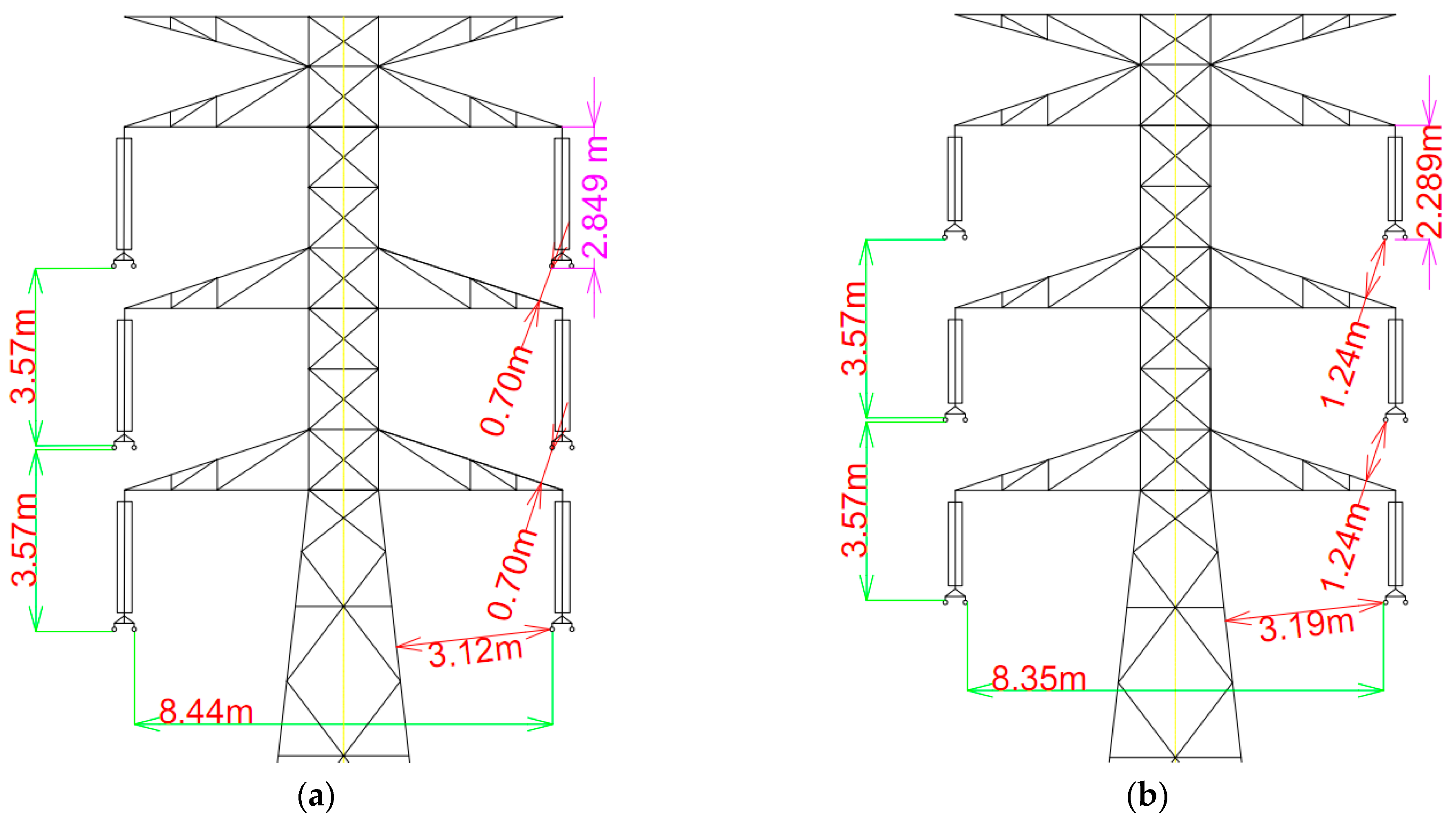
In Malaysia, a study regarding the uprating of the 132 kV transmission line proposed current uprating techniques. It was mainly focused on the reconductoring, i.e., conductor type, to improve conductor sag [
22]. However, there is still a lack of knowledge regarding the voltage uprating of the existing transmission lines in Malaysia. In this paper, the main contribution is to propose the voltage uprating method associated with techniques and processes on the existing 132 kV transmission lines. In this study, a significant concern of voltage uprating is a technical issue, including a phase-to-earth electrical clearance. The study demonstrated that the voltage uprating of the existing 132 kV transmission line is likely to be considered a minimal structural modification in order to fulfill electrical clearances requirements. However, it is worth mentioning that voltage uprating is a preeminent option rather than new transmission line development. The FEM simulations were carried out on the proposed voltage uprating model by considering transient overvoltages and power frequency magnitude to examine the withstand capabilities under various conditions (i.e., still air and wind conditions) on the insulation strength. The simulations results were compared with the estimated critical flashover voltage (CFO) as the benchmark.
3. Results and Discussion
The insulation strength of the phase-to-earth was a significant concern issued, and it shall experience a comprehensive evaluation. The proposed transmission model is usually exposed to transient overvoltages and power frequency, and subsequently, it could suffer from the most significant voltage and highest electrical stresses. Thus, the simulation by using FEM subjected at the front time of the BIL waveform was measured. The simulations results will comprehensively compare with the estimated CFOas the worst insulation strength benchmark before the existing transmission line adequate uprate to 275 kV transmission line.
The voltage profile at the minimum available electrical under still air (L1, L2 and L3), normal wind (L4, L5 and L6), and extreme wind (L7, L8, and L9) conditions at the top, mid, and bottom section crossarm was measured. In this study, the voltage profile overlay of the BIL, BIL + 10% and BIL + 25% at different structures of the crossarm and conditions showed a similar propagation pattern. For the backflashover cases, the voltage profile overlay of the proposed tower model under BIL, is shown in
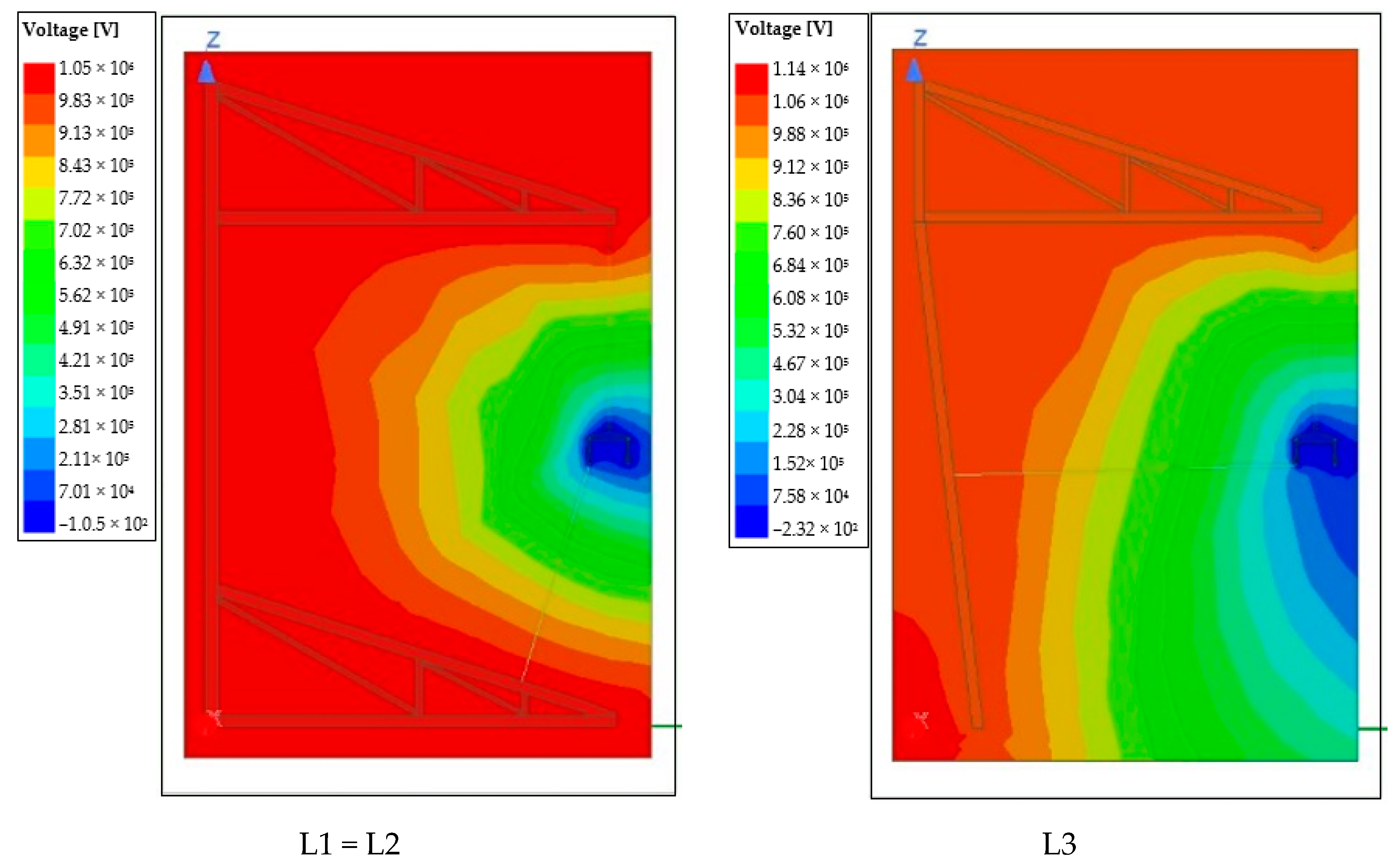
Figure 10. It is demonstrated that the highest voltage profile is initiated at the steel structure proposed tower and slightly decreases towards the phases of the conductor. It is believed that the decrement of voltage profile is due to propagating in different materials. Meanwhile,
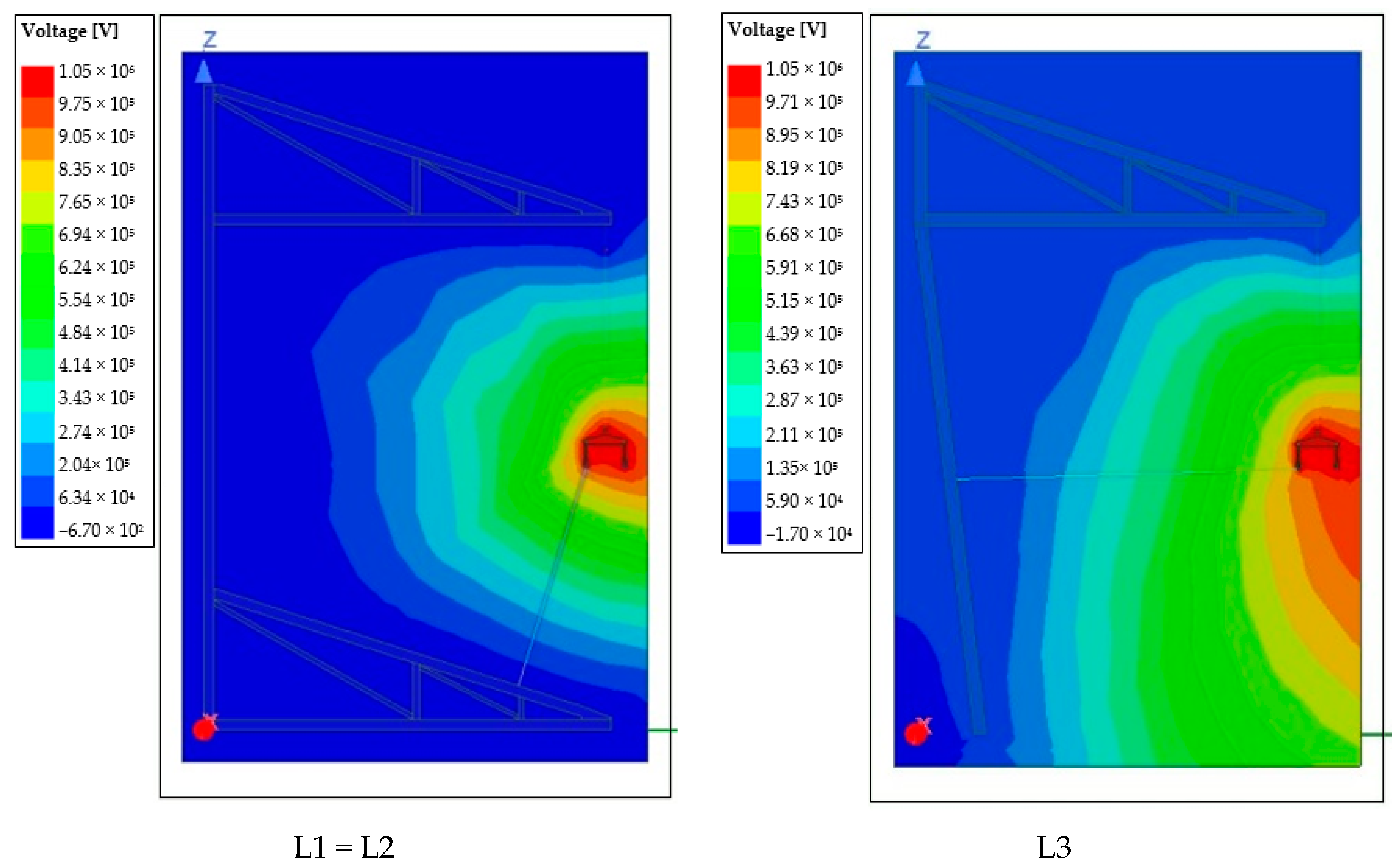
Figure 11 shows the shielding failure events in which voltage profile overlay starts initiation at the phases conductor and slowly reduces voltage stress once near the steel body structure.
3.1. Effect of Voltage Uprating for 132 kV Transmission Tower on the Voltage Profile under Still Air
Figure 12 shows the voltage magnitude at the L1, L2 and L3 with the different voltage stresses under backflashover and shielding failure events. For the backflashover event, it was found the voltage stresses, i.e., BIL and BIL + 10% at L1, L2 and L3, remained lower than the estimated CFO of 1089 kV, as can be seen in
Figure 12a. However, at 1.8 m of electrical clearance, the voltage stress at L1 and L2 for BIL + 25% remained higher than the estimated CFO for negative lightning. The voltage stress, i.e., BIL + 25% at the L3, was relatively close to the estimated CFO. The percentage of the difference on estimated CFO between simulations of voltage stresses, i.e., BIL, and BIL + 10%, was between 3.8% to 23.9%. It is believed that the insulation strength under lightning impulse is sufficient to operate of 275 kV transmission line throughout the requirement of the electrical clearance.
For the shielding failure under the case study, all L1, L2 and L3 experience significant insulation strength to withstand switching and lightning overvoltages, as shown in
Figure 12b. The percentage difference of estimated CFO for negative lightning between different BIL was between 30.7% and 71.3%, as summarised in
Table 10.
3.2. Effect of Voltage Uprating for 132 kV Transmission Tower on the Voltage Profile under Normal Wind Condition
The normal wind condition demonstrates a slight movement of the suspension string insulator due to environmental factors that could directly or indirectly influence the insulation strength. Malaysia’s electric utility operator has considered the 15° swing angles of the suspension string insulator as the normal wind condition. In this study, the minimum availability of electrical clearances for 15° swing angles was 2.07 m of phase-to-earth. There was a slight reduction of phase-to-earth electrical clearance between still air and normal wind condition, and its percentage difference was 13.8%.
For backlflashover under the case study, the voltage magnitude at L4, L5 and L6 under, i.e., BIL and BIL + 10% of voltage stresses are significantly lesser than the estimated CFO. At 1.8 m, the minimum electrical clearances, the BIL + 25% at L4, L5 and L6 shows exceeded the estimated CFO, as shown in
Figure 13a. The percentage of increment between the estimated CFO and L4, L5 and L6 under BIL + 25% are 4.7 and 6.9%, as summarised in
Table 11.
The voltage magnitude shows sufficient electrical clearances for shielding failure events even the L4, L5, and L6 stresses with BIL, BIL +10%, and BIL +25%.
Figure 13b shows clearly at 2.0 m of electrical clearances at phase conductor to structure steadily remains lower than estimated CFO.
It is believed the reduction of electrical clearances is due to normal wind conditions, which lead slight decrease in insulation strength. However, it is noticed that the insulation strength could withstand almost 2.0 m of electrical clearances even voltage stresses up to BIL + 25% were applied.
3.3. Effect of Voltage Uprating for 132 kV Transmission Tower on the Voltage Profile under Extreme Wind Condition
Under extreme wind conditions, the string suspension swings by 57°, and its electrical clearance is significantly lower than still air and normal wind conditions. The percentage of difference in electrical clearances between under still air and extreme wind conditions is between 58.3% and 68.8% at the different crossarm sections, as summarised in
Table 12. It is believed that a normal operating voltage of 132 kV uprating the transmission line could lead to flashover due to insufficient electrical clearance. The withstand voltage of the power frequency is much lower than transient overvoltages withstand voltages. Hence, the withstand voltage of the power frequency was considered in this study.
The simulations results clearly show that a similar trend of stresses and voltage profiles was obtained for all cases. Both cases under BIL, BIL +10%, and BIL +25% at different crossarm sections, none of the cases experienced high stress or having maximum voltage magnitude exceeds the CFO for the distances that could potentially give the 50% of having the flashover as can be seen in
Figure 14. The insulation strength of the proposed voltage uprating of the 132 kV transmission under extreme wind conditions benefits withstanding capability. The electrical clearance of the phase-to-earth under extreme conditions is almost double the required minimum electrical clearance of 0.51 m for the power frequency needed for 275 kV transmission line operation. Meanwhile, the percentage of the difference between the estimated CFO and all cases ranges from 19.2 to 68.7 %. It is worth mentioning that the margin could be sufficient for load operating conditions.
4. Conclusions
In conclusion, the existing 132 kV transmission lines under the case study were proposed to uprate to the new voltage level of 275 kV using the voltage uprating method. The techniques involve in voltage uprating are by increasing insulation strength and improving air conductor clearances. It is found that the voltage uprating of the existing 132 kV transmission lines fulfilled all the electrical clearances such as phase-to-earth, phase-to-phase and phase-to-ground with consideration of still air, normal wind, and extreme wind conditions. It was also revealed the electrical clearances of phase-to-phase and phase-to-ground are almost double the required minimum requirement needed for 275 kV transmission lines operation. It was believed the margin of electrical clearances ought to be sufficient for operating maximum load conditions.
A simulation study was carried out to evaluate the insulation strength of the proposed model by considering transient overvoltages, power frequency, and several conditions. Based on the simulations results under still air and normal wind conditions, it is found the voltage magnitude at BIL, and BIL +10% during backflashover events are much lower than the estimated CFO. For backflashover and extreme wind conditions under the case study, no voltage magnitude at all BIL was found to be exceeded the estimated CFO that could potentially cause flashover. Meanwhile, for shielding failure events under still and wind conditions, there is a significant difference in the percentage between the estimated CFO and all level BIL cases are ranging from 15.9 to 71.3%. It is worth to mention that the proposed voltage uprating of the existing 132 kV transmission line satisfies the insulation strength at BIL for all cases and is believed fit to operate for a 275 kV transmission line.


 ,
, 


