Abstract
Taking a 1000 MW turbine generator as the research object, the short-circuit fault in electrical disturbance is analyzed. Since it is very difficult to carry out fault analysis experiments and research on actual systems, simulation analysis is one of the more effective means of electrical fault diagnosis; the simulation’s results approach the actual behavior of the system and are ideal tools for power system analysis, and can provide an empirical basis for practical applications. The short-circuit fault model of the SIMULINK power system is built to analyze the two types of faults of generator terminals short-circuit and power grid short-circuit. The impact load spectrum, fault current and speed fluctuation between low-voltage rotors were extracted and analyzed. The conclusion is that the impact value of electromagnetic torque at the generator terminal is greater than that on the power grid side. The impact value of a two-phase short-circuit at the generator terminal is the largest, and that of a three-phase short-circuit on the power grid side is the smallest. The transient impulse current of a three-phase short-circuit at any fault point is greater than that of a two-phase short-circuit; the impulse current of the grid side short-circuit is much greater than that of the generator terminal short-circuit; the speed fluctuation and fluctuation difference caused by the three-phase short-circuit in the grid side are the largest. The alternating frequency of the transient electromagnetic force of the four kinds of faults avoids the natural frequency of the torsional vibration of the shaft system, and the torsional resonance of the shaft system in the time domain of the short-circuit fault will not appear. However, after the fault is removed, the residual small fluctuation torque in the system has a potential impact on the rotor system. This research shows an analysis of the structural integrity and safe operation of turbine generator units after a short-circuit fault, which can not only be applied to engineering practice, but also provide a theoretical basis for subsequent research.
1. Introduction
A steam turbine generator set is the core component of power energy production, and at present, the main power energy production structure in China is still dominated by thermal power, which is gradually developing into large units with high capacity and high parameters. With the gradual increase in the unit capacity, the rotor system is also developing towards a more complex, long-axis system, so the torsional vibration of turbine generator units is becoming a problem that cannot be ignored. Once a torsional vibration fault occurs, it will cause irreversible damage to the rotor, causing major accidents and huge economic and property losses. Therefore, research on torsional vibration has great theoretical and engineering application value. The analysis and calculation of shaft torsional vibration is the basis of shaft design and the safety analysis of turbo-generator units.
The analysis and calculation of shaft torsional vibration characteristics can be summarized as the analysis of dynamic response and inherent characteristics. The analysis methods for the inherent characteristics of torsional vibration mainly include the transfer matrix method, the characteristic root analysis method, the Lagrange method and the equivalent impedance method [1,2]. There are also new and improved algorithms, such as the stiffness coefficient and inertia coefficient method proposed by Chow J.H. [3], based on the least square method. Fairbairn et al. [4] proposed a method for identifying the modal parameters of rotor shafting, and the number of variables needed in the identification process was the same as that of the identified modes. Li et al. [5] proposed a two-channel active damping control measure. One is a proportion integration differential damping term with frequency difference, which is used to reduce the torsional vibration caused by the frequency difference between the fan and shafting; the other adopts the torsional vibration angle as the feedback signal, and an additional damping term is formed by the bandpass filter and trap filter. The strategy can increase the electromagnetic torque and suppress the torsional vibration of the drive chain. Finally, modeling and simulation using Matlab/Simulink show that this method can effectively suppress the torsional vibration of the drive chain without affecting power generation. Masayuki et al. [6,7] assessed a simple tool for the analysis of the torsional vibration of the rotor shaft of a turbine generator, which is interconnected with a power system with self-commutated converters. Tang et al. [8] used a Riccati transfer matrix and Holzer method to calculate the inherent characteristics of the torsional vibration of rotating machinery shafting, compiled the corresponding program, and introduced the method of reducing the order of the model. The correctness of the model reduction method and calculation program was verified by calculating the natural frequency and vibration mode of the torsional vibration of subsynchronous resonance simulator shafting. Zhao et al. [9,10,11] investigated the free vibration behaviors of a functionally graded (FG) disk–shaft rotor system, which was reinforced with graphene nanoplatelets (GPL) resting on elastic supports. Liu et al. [12,13,14] deduced the torsional vibration model of the shafting with dynamic frequency based on the consideration of the dynamic conditions of the shafting, studied the dynamic frequency problem of the torsional vibration of the shafting of a 300 MW turbo-generator unit, and concluded that the torsional vibration of the shafting of the turbo-generator unit at the existing rotational speed can be ignored. Zhao et al. [15,16,17] shed important light on the design of a novel graphene-reinforced blade–shaft system offering remarkably improved dynamic performance. Pan et al. [18,19] studied the influence of the change in non-harmonic parameters on the vibration characteristics of a bladed disk system, and obtained the conclusion that the vibration mode change trends of the bladed disk system and those of the bladed disk were basically the same. Kundur et al. [20,21,22] gave a method for system control and nonlinear simulation in a power system simulator used on the object virtual network integrator of UBC. The definition and classification of power system stability were introduced. Zhao et al. [23,24,25,26,27,28,29] studied the rubbing of a mistuned bladed disk system with blades of variable thickness, and an elastically supported shaft-variable thickness blade-coupled finite element model was established. Yuan et al. [30] studied the optimized arrangement of the vibration damping in a dissonant bladed disk system by establishing a centralized parameter model. According to different intelligent optimization algorithms, a new optimization arrangement method was proposed. Machowski et al. [31,32] proposed that the model of phase-shifting transformer can be divided into an isotropic part and an anisotropic part. The isotropic part can be included in the network model, and the relevant admittance matrix can be inversed by the process assigned to the symmetric matrix. Navid et al. [33,34,35] proposed a six-phase motor saturation CPVBR model, which contains the main flux saturation, achieving magnetic decoupling and constant RL grafting. This new magnetic decoupling CPVBR (DCPVBR) model has many advantages, which can be easily interfaced with inductance and/or power electronic circuit components, and can be realized in common simulation programs. Zhao et al.’s [36,37] improved parallel algorithm constructed a graphics processing unit based on a compute unified device architecture, and its performance was analyzed. The results show that using optimization results can reduce the amplitude and localization of the forced vibration response of a bladed-disk system. At the same time, optimization based on a compute unified device architecture framework can improve computing speed. Sun Hetai [38] expounded the importance of torsional vibration research for a turbo-generator set, analyzed the main causes and types of torsional vibration in a turbo-generator set, and focused on a method for testing the torsional vibration of a turbo-generator shaft system. Kimbark et al. [39,40,41,42] studied how to improve the system stability without the risk of subsynchronous resonance, and analyzed double imbalance experiments. Dome [43] gave a description and mathematical treatment method for obtaining a modulated RF power with good conversion efficiency from the commonly used DC source. The method adopted is to modify the load line of the saturated RF amplifier so as to take care of the positive peak, and to mesh the negative peak of the amplifier. Sajjad et al. [44] analyzed the influence of the protection device on each overvoltage index. It was also found that only considering the amplitude of the transient overvoltage is not enough to ensure the safety of a transformer in a frequent switching inrush current. Isidoro et al. [45,46] provided algorithmic proof of a theorem by D. K. Wagner, according to which every almost-planar graph can be reduced to the graph K3, 3 by some sequence of series/parallel reductions and delta–wye exchanges, such that the reduction sequence is formed by almost-planar graphs.
Taking a 1000 MW turbine generator set as the research object, a system model of the turbine generator set is built based on SIMULINK. The ode23tb algorithm is used to simulate and analyze the faults of the two-phase and three-phase short-circuit at the generator terminals, and the two-phase and three-phase short-circuit at the grid side through the synchronous generator module and the multi-mass steam turbine module based on the flux linkage equation [47]. The transient electromagnetic impact torque and short-circuit current fluctuation under four fault conditions were extracted and analyzed; the analysis results can provide a database corresponding to the short-circuit fault involved in the electrical disturbance in the turbo-generator set [48,49].
2. Solving of Torsional Vibration Natural Frequency of Shafting
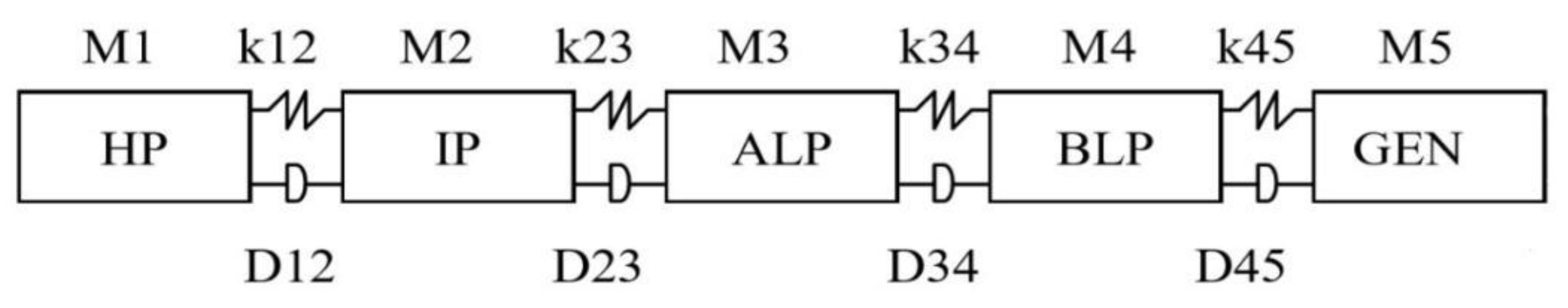
The natural frequency analysis of the torsional vibration of the turbo-generator set is the basic content of torsional vibration research in engineering. The Block Lanczos method for solving torsional natural frequency can also meet the needs of practical engineering in terms of accuracy and calculation convergence rate. The research object is decomposed into a multi-stage and multi-degree-of-freedom spring-damping system, and the turbine generator set can be simplified as shown in Figure 1.
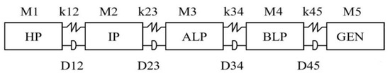
Figure 1.
Turbo-generator with multiple degrees of freedom system.
Under the premise of the normal operation of the oil system, the friction damping of the turbine generator rotor is very small, and the damping effect can be ignored. The second-order differential equation of dynamics is
The differential form solution of Formula (18) can be expressed as
Factorization is performed by the Cholesky method, and is rewritten as
Equation (20) can be expressed as , where is the lower triangular matrix (;; ), converting matrix A to the lower triangular matrix.
where , satisfying , where the matrix is a triangular matrix that can be expressed as
After calculation, the eigenvectors and eigenvalues of the characteristic equation shown in Equation (1) correspond to (natural frequency) and (vibration mode vector) of the studied elastic system, respectively.
The first three low-order torsional vibrations in practical engineering comprise the main monitoring range. As can be seen from Table 1, the natural frequency of the first-order torsional vibration of the unit is 14.5 Hz, the natural frequency of the second-order torsional vibration is 26.5 Hz, the natural frequency of the third-order torsional vibration is 34 Hz, and the natural frequency of the fourth-order torsional vibration is 61.9 Hz. Therefore, the rotor system precludes the natural frequency of the torsional vibration at the working frequency of 50 Hz, so there is no power frequency resonance.

Table 1.
The solution result of torsional vibration natural frequency.
3. Construction of Electrical Short-Circuit Fault Model
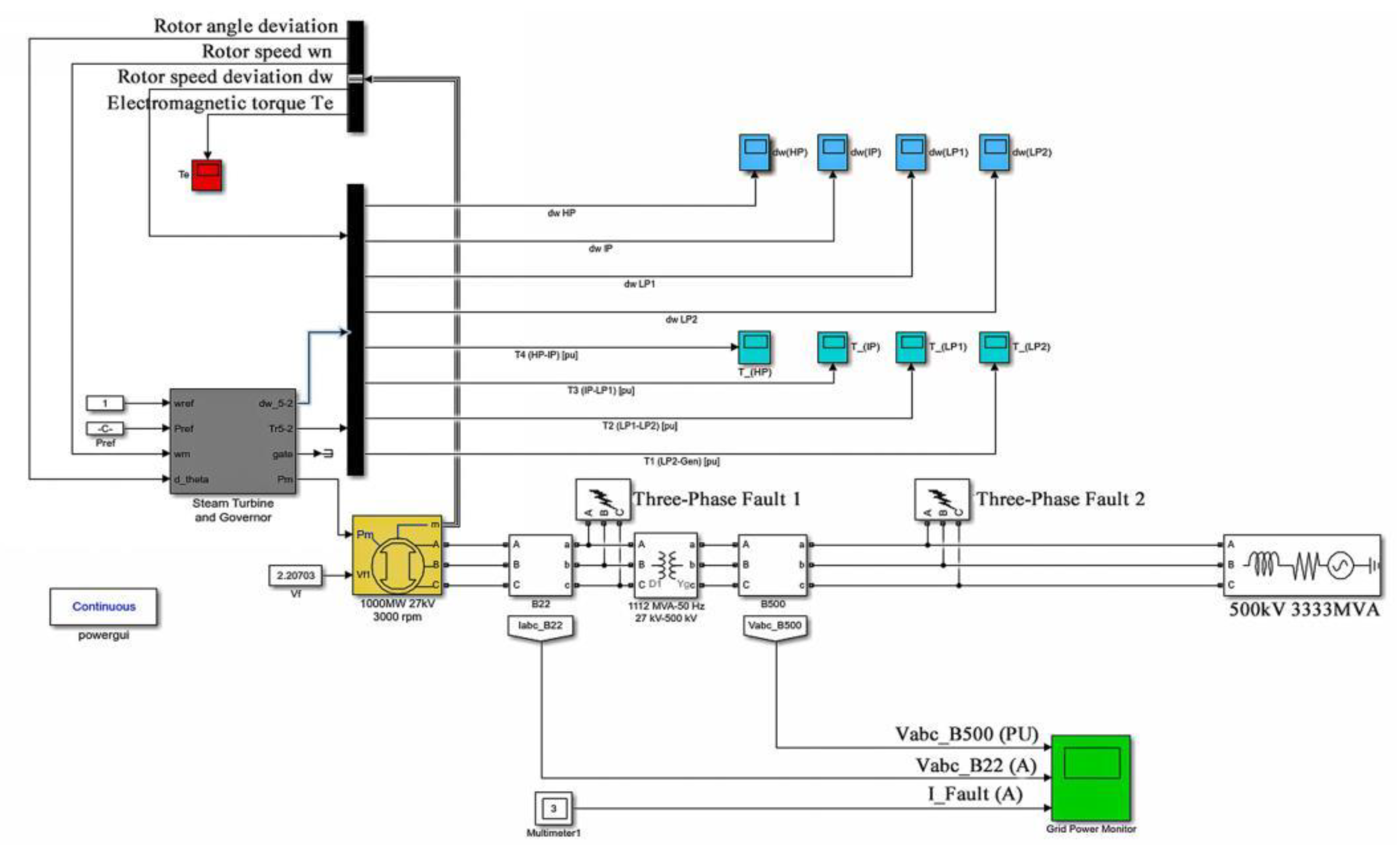
3.1. SIMULINK Electric Short-Circuit System Simulation Model
The most common fault in power systems is a short-circuit. Short-circuits are mainly divided into three-phase short-circuits, two-phase short-circuits, single-phase short-circuits. The probability of a three-phase short-circuit is not high, but it is the most dangerous fault in a power system. The most common fault is a single-phase grounding short-circuit, accounting for about 65–70% of total short-circuit faults. MATLAB is used for modeling and simulation analysis, which avoids the complicated and long programming process, and the simulation results are close to the actual behavior of the system, so this is an ideal tool for power system analysis. It is convenient, practical and flexible, providing an effective research platform for power system researchers. Simulink is attached to MALAB as a tool library, which is a software package for modeling and simulating dynamic system. It provides a block diagram modeling interface for users, which can complete the modeling of continuous systems, discrete systems, and continuous and discrete mixed linear and nonlinear systems. It also supports the simulation and analysis of the dynamic performance of multi-rate systems with multiple sampling rates. MATLAB is an engineering calculator represented by matrix operation. The integrated SIMULINK model library is embedded with the Simscape Component and Specialized Technology module library, which is mainly developed for power system simulation, including an electromechanical system module, a power module, a controller switching library, etc. [50]. The electrical short-circuit fault model of a 1000 MW turbine generator set is built by calling the synchronous generator model and steam turbine model in the Simscape Component calculation library, as shown in Figure 2. The power generation model takes an actual 1000 MW unit as the research object, and builds the overall power system simulation circuit, including the steam turbine, synchronous generator, transformer, and other main modules. The right side is provided with a constant 500 kV AC power supply to simulate the power grid. On the left side, the turbine and generator are coaxial through the series module of steam turbine and synchronous generator, which constitutes the actual power production turbine generator model. The generator output is 27 kV AC, and the transformer module is boosted to the same grid voltage. The line contains two fault points, three-phase fault 1 and three-phase fault 2, which are the short-circuit fault point of the generator terminals and the short-circuit fault point of the line of the power grid, respectively.
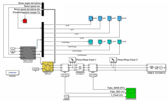
Figure 2.
Short-circuit fault simulation circuit system.
3.2. SIMULINK Turbine Generator Unit Model
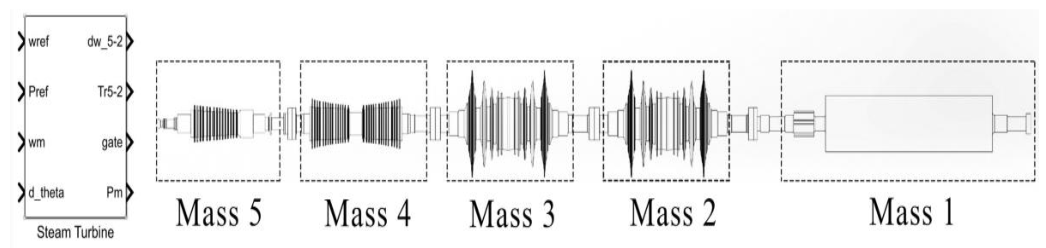
The model of the 1000 MW turbine generator set is built by the steam turbine module embedded in the SIMULINK Toolbox. The module includes the complete steam turbine system and generator system, and integrates five mass blocks, corresponding to the high-pressure rotor, the medium-pressure rotor, two low-pressure rotors and the generator rotors of the turbine generator set, all connected together through the coupling. Coupling refers to a device that connects two shafts or shafts with rotary parts, which rotates in the transmission from motion into power and which does not disconnect under normal conditions. Sometimes, it is also used as a safety device to prevent the connected parts from being subjected to excessive load, which plays the role of overload protection. Couplings can be divided into rigid couplings and flexible couplings. The five mass blocks are connected by rigid couplings. There is no relative displacement in the radial and axial directions of the two rotors, which is conducive to keeping the rotor center unchanged, as shown in Figure 3.

Figure 3.
Turbo-generator simulation module.
Several mass blocks are connected by the transfer function, involving boundary parameters including the turbine volume time constant, inter-rotor torque transfer factor, inter-rotor coupling stiffness coefficient and rotor inertia [51]. The simulation input parameter boundary of a 1000 MW unit is given in Table 2.
Table 2.
Input parameters of steam turbine simulation module.
The short-circuit faults are transiently analyzed, and the factors that do not consider the work of the boiler and the influencing factors of the regulating system are treated as steady-state constants. The transfer mode of work torque between the rotors of each cylinder is shown in Figure 4, in which the output parameters Tt_2-Tt_5 are the torque transfer between the rotors [52].
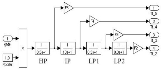
Figure 4.
Power transmission mode of each rotor of turbo-generator.
3.3. SIMULINK Synchronous Generator Model
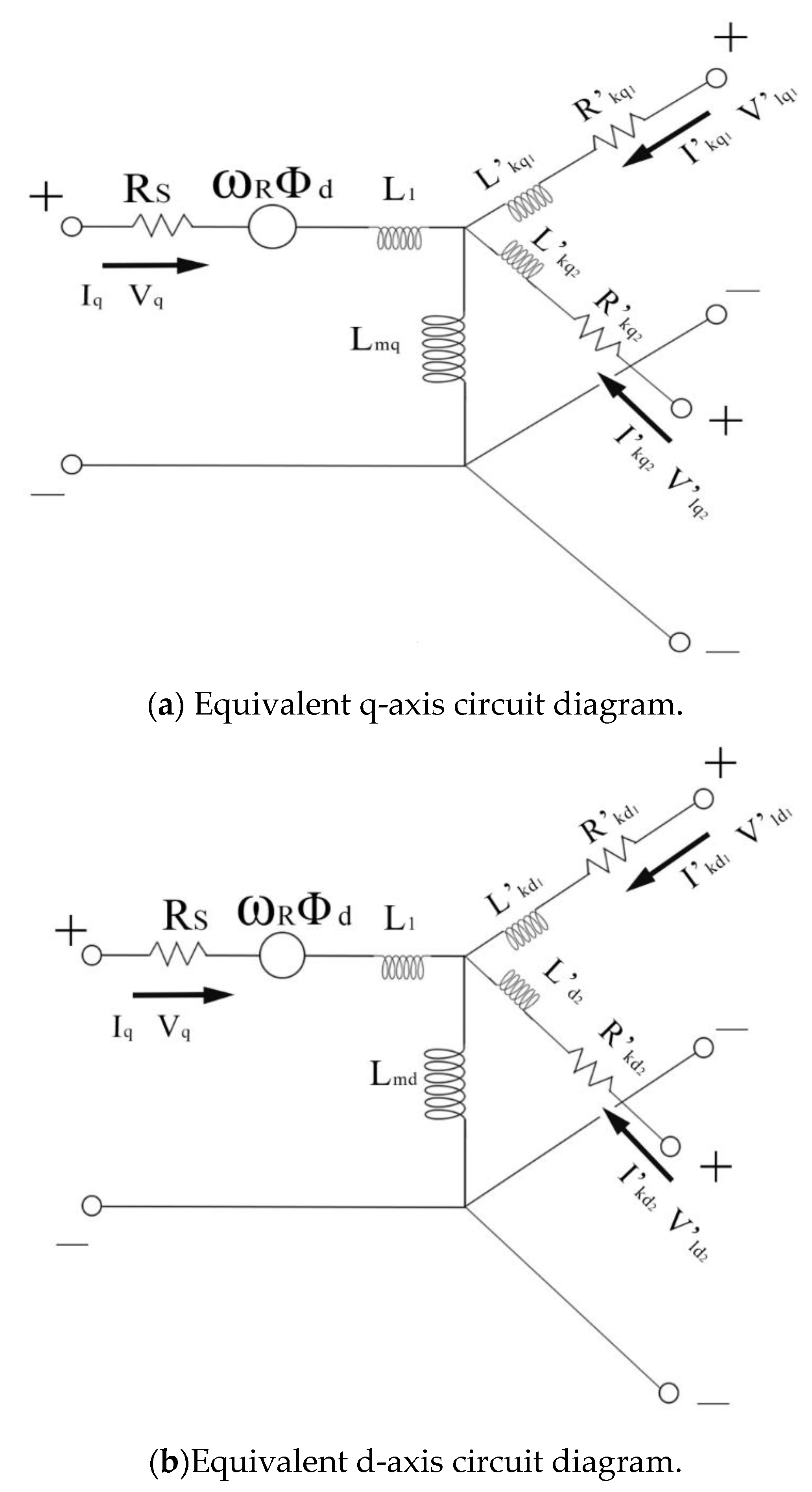
The load part of the rotor system uses the synchronous machine module embedded in the SIMULINK Toolbox, which considers the dynamic characteristics of stator, excitation and winding damping. The equivalent d-axis and q-axis circuits of the model are shown in Figure 5.

Figure 5.
Synchronous generator model equivalent circuit diagram.
In Figure 5, R and Rs represent the generator rotor and stator, respectively. L and Lm represent leakage inductance and excitation inductance, respectively. f and k represent excitation and damping windings, respectively [53,54]. The synchronous generator model is represented by the sixth-order state space model, and the corresponding equation is
The basic equation of the synchronous generator can be expressed as
In Equation (12), Va, Vb and Vc are the voltage of the three-phase winding generator, Vf is the voltage of excitation winding, and i is the resistance of each phase of the three-phase winding of stator a, b, c. is the total magnetic chain of each phase winding, is the derivative of the above magnetic chain to time, and the flux equation corresponding to the synchronous generator can be expressed as
In Equation (13), Laa, Lbb and Lcc denote each phase of the self-inductance coefficient, and Lac, Lab and Lfd are the interphase and axial mutual inductance coefficients. In the actual situation, the spatial position between the stator winding and the magnetic field is always undergoing dynamic change, and the self-inductance and mutual inductance of the stator winding are also constantly changing. By using Park transformation and a per-unit system, it is determined that the synchronous speed is 1, and the basic equation of the synchronous generator is equivalent to the following equation:
In Equations (14)–(22), xad represents the d-axis armature reaction reactance. Rx represents the corresponding parameters for the rotor. Based on the above theoretical consideration, this synchronous model is used to simulate the QFSN-1000-2 generator, and the corresponding boundary parameters are shown in Table 3.
Table 3.
TQFSN-1000-2 synchronous generator module’s input parameters.
4. Electrical Short-Circuit Fault Simulation Analysis
4.1. Simulation Analysis of Generator Terminals Two-Phase Short-Circuit
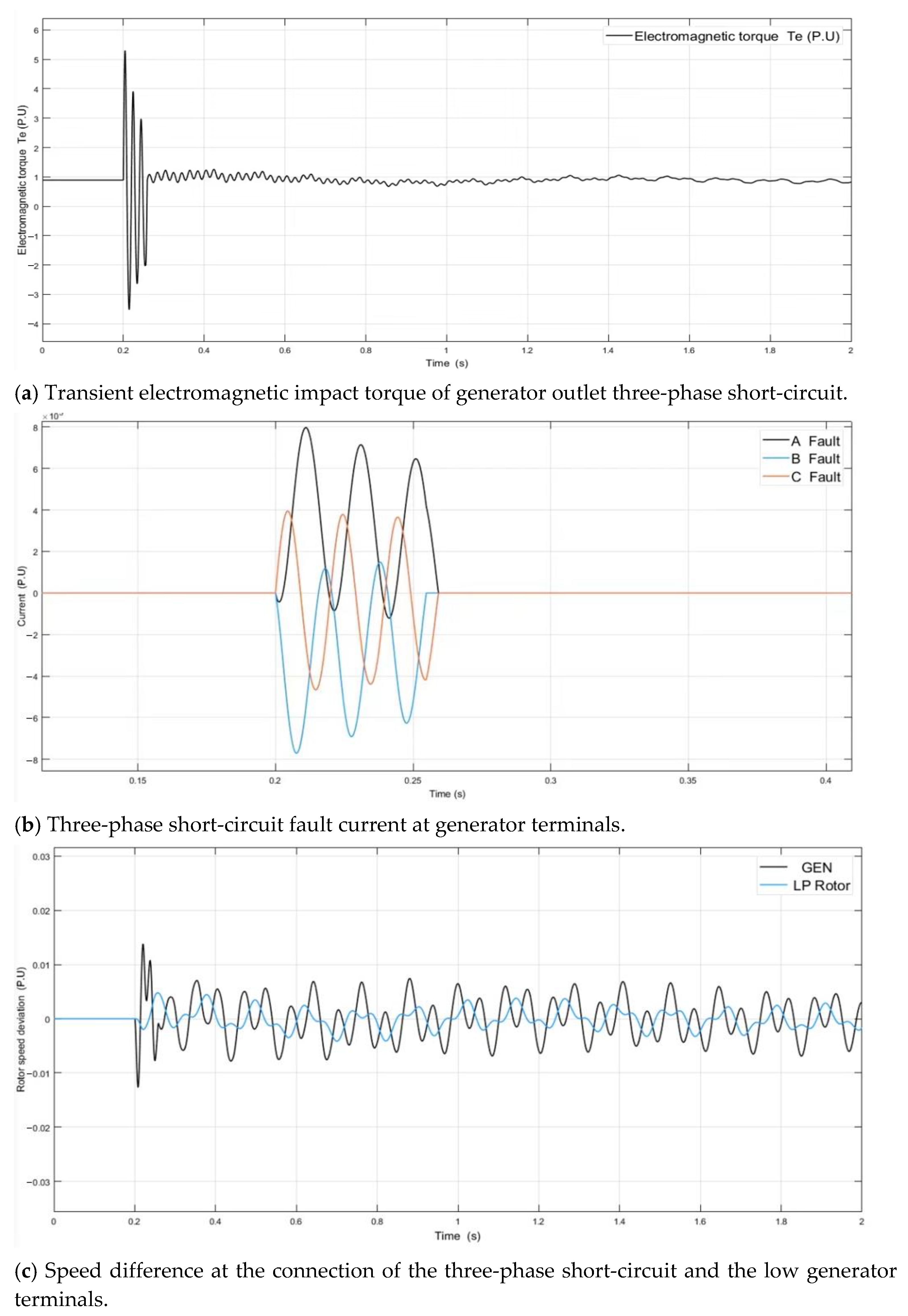
The generator outlet short-circuit fault is realized by the three-phase fault module in the SIMULINK Toolbox, and the position is shown in Figure 1. The generator terminals short-circuit fault 1. The generator is set to impart 80% load before the fault occurs, and the system’s simulation time domain is 2 s. The short-circuit fault between phases A and B occurs at 0.2 s, and it is removed at 0.25 s. The short-circuit time is 0.05 s. The algorithm ode23tb is used to solve the unit value of electromagnetic torque, fault current and velocity difference at the connection of the low-voltage generator under the transient fault, as shown in Figure 6 [55,56].
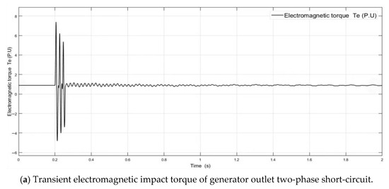
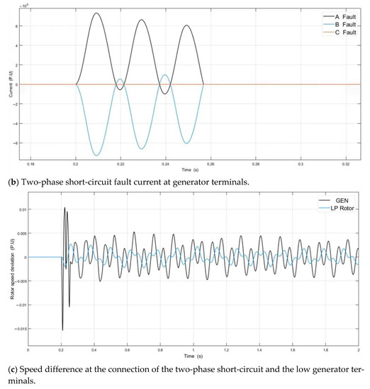
Figure 6.
Characteristic curve of generator terminal’s two-phase short-circuit fault.
Figure 6a shows that the transient electromagnetic torque of the generator undergoing a short-circuit fault is about 7 times that under stable conditions, and the short-circuit current of the fault phase circuit also changes instantaneously, as shown in Figure 6b. In the fault time domain, speed fluctuation appears at the connection between the low-voltage rotor and the generator rotor, and the speed oscillation reaches its maximum value at the moment of fault removal, as shown in Figure 6c.
Since the impulse excitation obtained by the SIMULINK simulation is a per unit value, it is not beneficial to the subsequent quantitative analysis of transient dynamics. The nominal values of torque and current calculated by the simplified load flow module in the SIMULINK Power GUI module are shown in Table 4 [57]. The calculation of the given reference parameters shows that the maximum value of transient alternating electromagnetic torque generated by a two-phase short-circuit reaches 2.14 × 10⁷ Nm.
Table 4.
Known value under 80% load of generator.
4.2. Simulation Analysis of Generator Terminal’s Three-Phase Short-Circuit
The position of the three-phase short-circuit at the generator terminals is the same as that of the two-phase short-circuit. The short-circuit fault form is changed to the three-phase short-circuit at the generator terminals, and the cut-off time remains unchanged. Similarly, the ode23tb algorithm is used to solve the transient electromagnetic and short-circuit fault current of the generator, as shown in Figure 7.
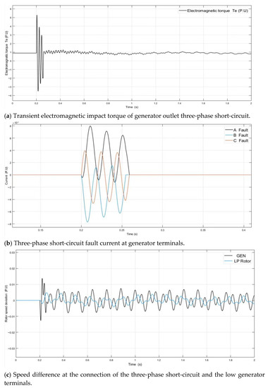
Figure 7.
Characteristic curve of generator terminal’s three-phase short-circuit fault.
For example, in Figure 7a,b (in contrast to Figure 6a,b), there is a visible generator terminal three-phase short-circuit transient current impulse, the value of which is greater than the two-phase short-circuit, but the transient electromagnetic torque is less than the generator terminal’s two-phase short-circuit. Compared with the generator two-phase short-circuit, the low-frequency oscillation duration of the electromagnetic torque after the three-phase short-circuit fault is removed is longer, and the frequency of the transient alternating electromagnetic impact torque is lower than that of the two-phase short-circuit. Figure 7c shows that the transient fluctuation in the speed difference between the low-voltage rotor and the generator is greater than that of the two-phase short-circuit fault at the generator terminals. The maximum transient speed fluctuation is 39 rpm, and after the fault is removed, the speed fluctuation cannot immediately return to the steady state.
4.3. Simulation Analysis of Two-Phase Short-Circuit on the Power Grid Side
After the short-circuit fault position is moved to the transformer, the line resistance is ignored to simulate the short-circuit fault of the power grid near the generator.
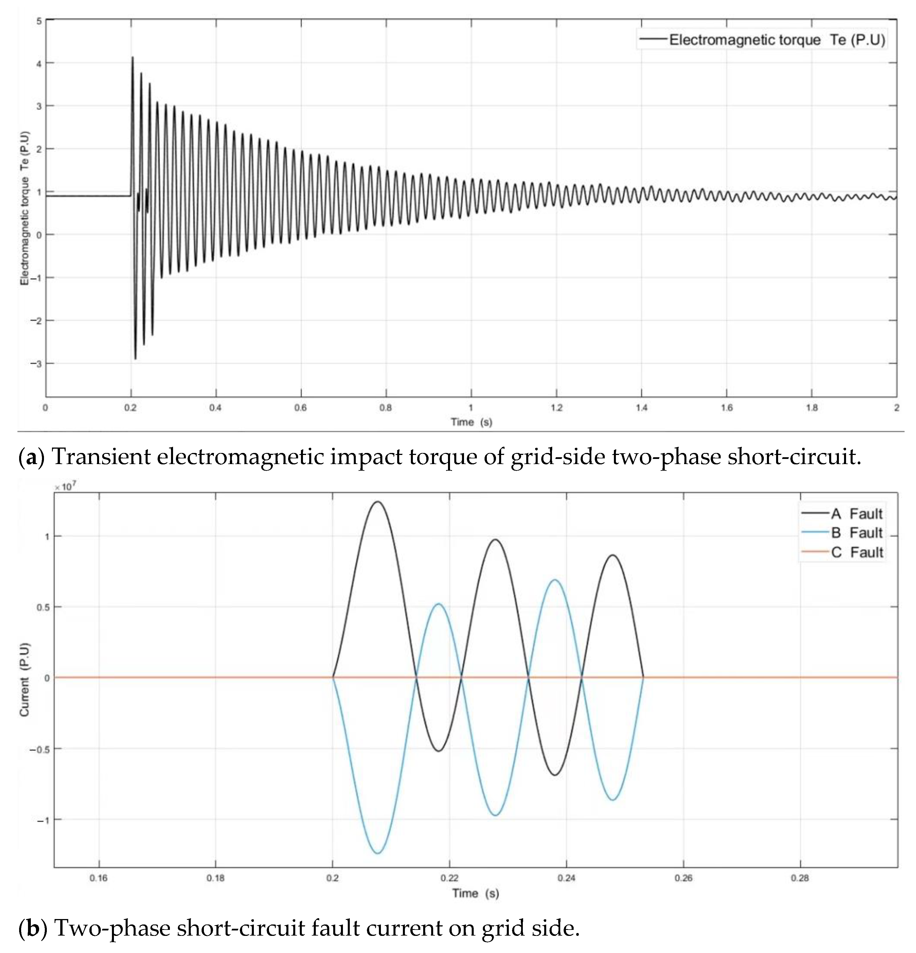
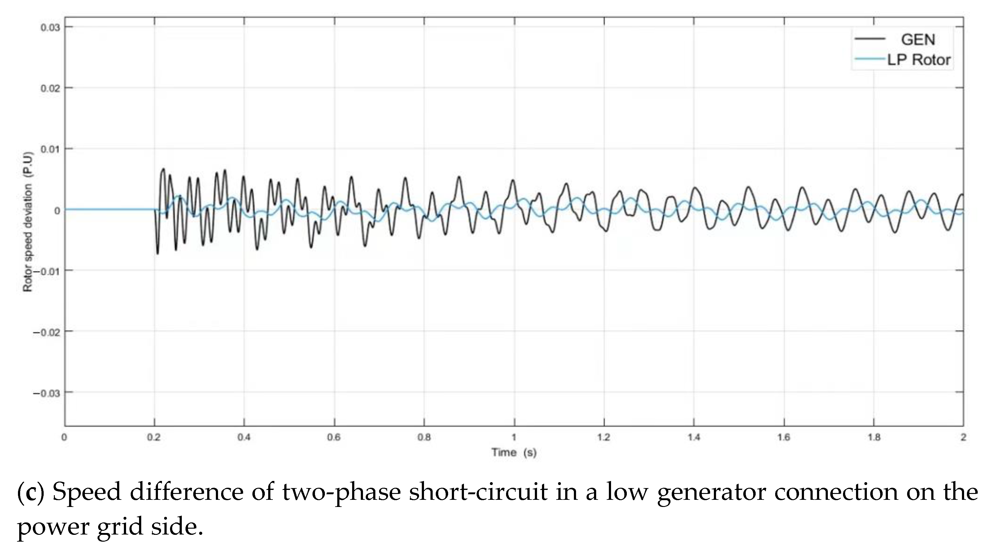
In order to control the boundary variables, the boundary setting of the grid-side short-circuit fault module is consistent with the above setting, and the cut-off time and simulation algorithm are consistent. The transient electromagnetic impact torque and fault current fluctuation under grid-side short-circuit fault conditions are obtained as shown in Figure 8.
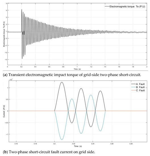
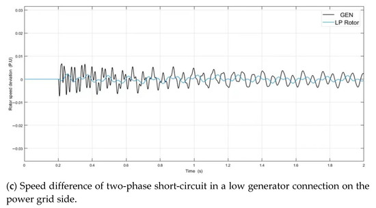
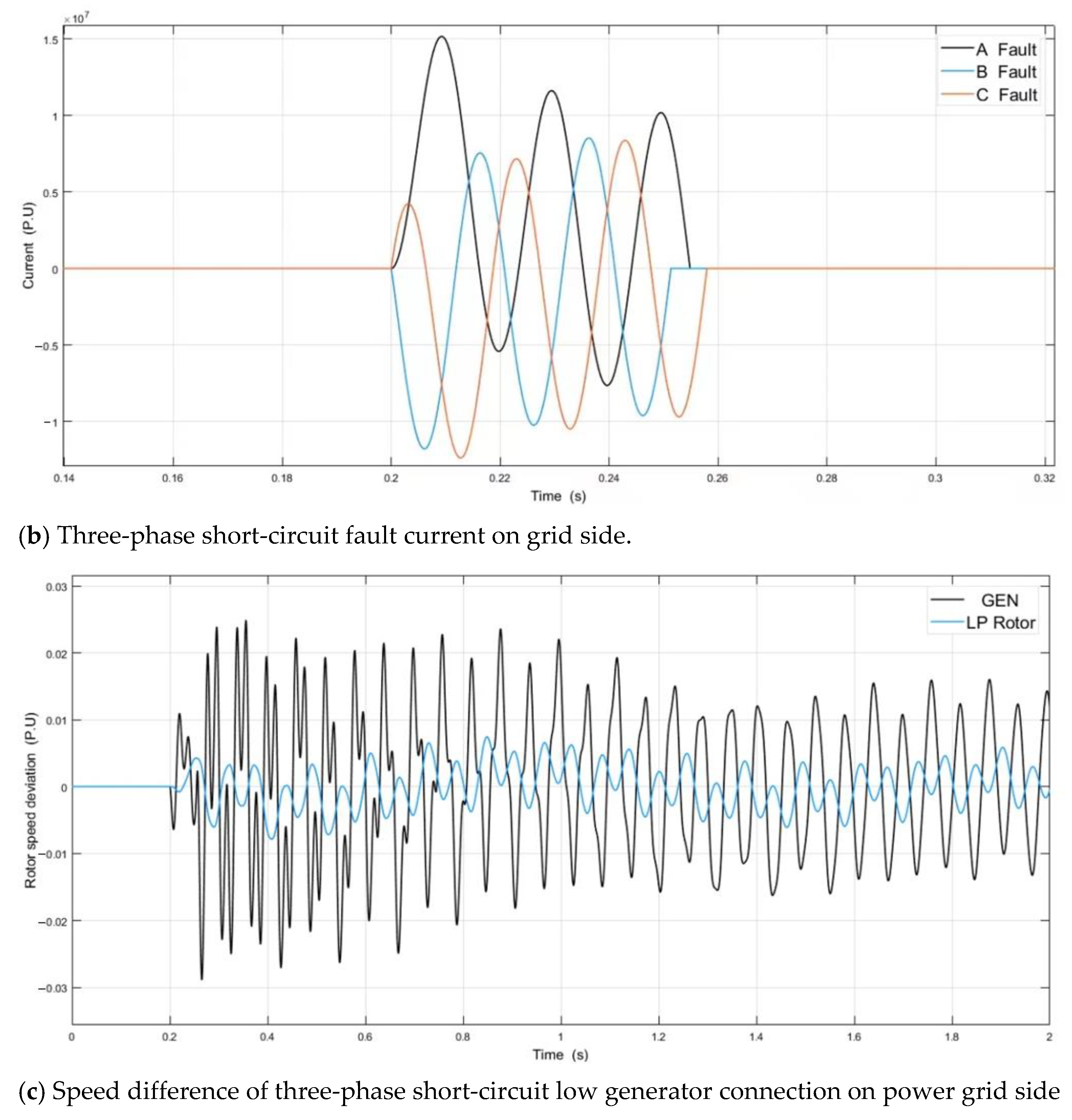
Figure 8.
Characteristic curve of two-phase short circuit fault.
Combined with the simulation results of the generator terminal’s short-circuit fault, in Figure 8a, the transient electromagnetic impact torque of the grid-side two-phase short-circuit is lower than that of the generator terminal’s two-phase short-circuit by 43.7%, and the maximum forward transient impact generated during the period is as much as 1.35 × 10⁷ N∙m. The amplitude of the power grid fluctuation is greater than that of the generator terminal’s short-circuit, and the duration is longer. The fault impulse current is much larger than the generator terminal’s two-phase short-circuit, as shown in Figure 8b.
Figure 8c shows that the speed fluctuation frequency of the connection between the low-voltage rotor and the generator is higher than that of the generator terminal’s short-circuit fault, but the transient speed difference is less than that of the generator terminal’s short-circuit fault, and the maximum fluctuation is below 30 rpm.
4.4. Simulation Analysis of Three-Phase Short-Circuit on the Power Grid Side
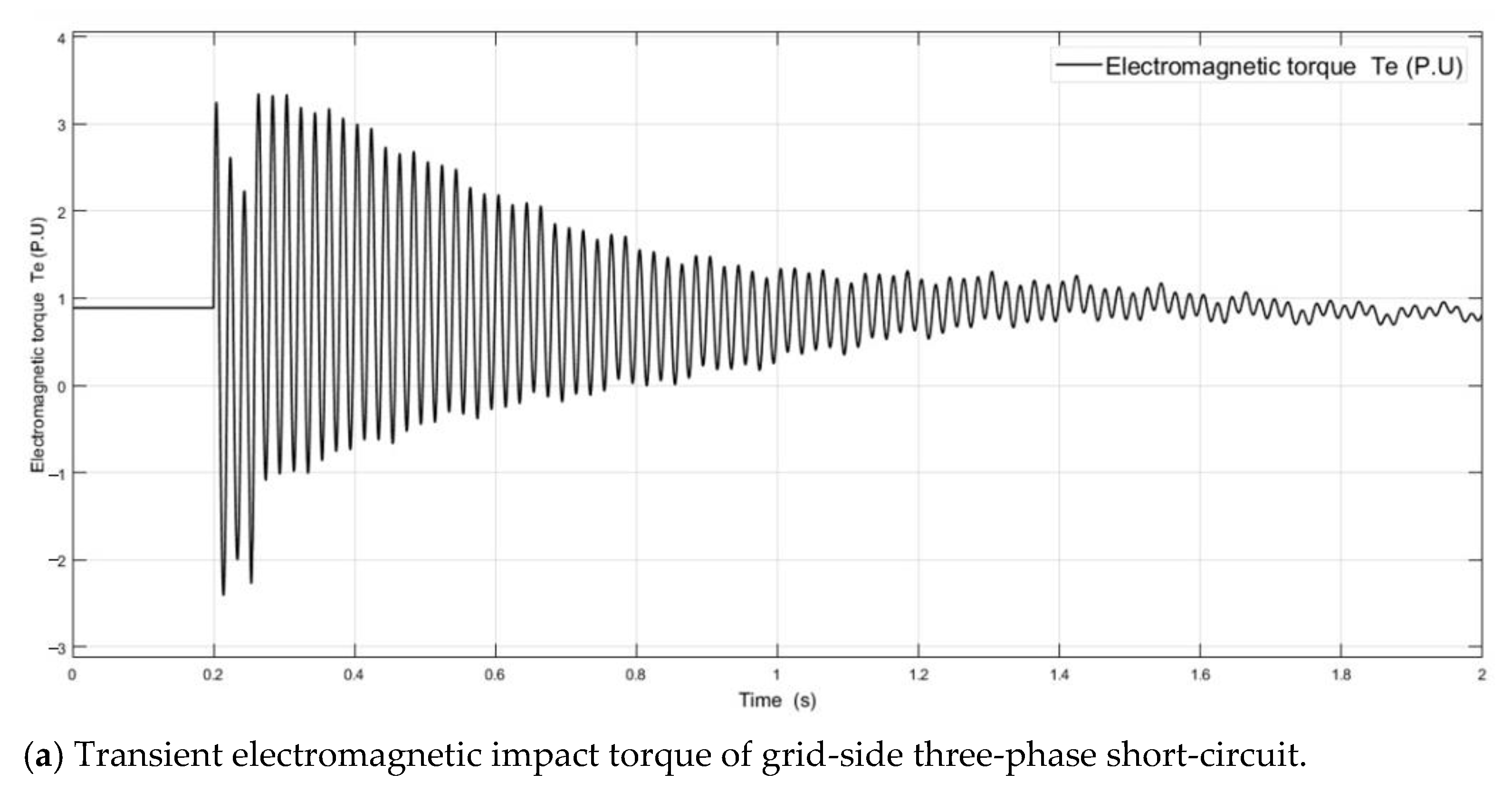
The grid-side short-circuit fault variable is changed to a three-phase short-circuit, while the fault cutting time and ode23tb solver are unchanged. The transient electromagnetic impact torque and short-circuit fault current of the generator are obtained as shown in Figure 9.

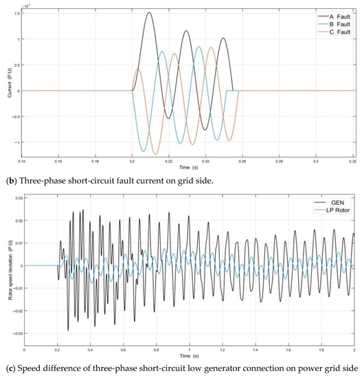
Figure 9.
Characteristic curve of three-phase short circuit fault.
As shown in Figure 9a,b, the electromagnetic transient impact torque of the three-phase short-circuit fault on the grid side is less than that of the two-phase short-circuit fault on the grid side, so the amplitude of the transient electromagnetic torque fluctuation generated at the lifting time is greater than that of the two-phase short-circuit fault on the grid side. The subsequent attenuation disturbance time is longer than the generator terminal’s short-circuit fault time.
Figure 9c shows that the speed fluctuation between the low-voltage rotor and the generator rotor after the fault shock is the most severe of the four short-circuit faults, which is twice as large as the two-phase short-circuit on the grid side. The fluctuation frequency is similar to the previous fault, and cannot immediately return to the steady state; the maximum transient speed fluctuation is more than 60 rpm.
5. Analysis of Short-Circuit Fault Simulation Data
5.1. Electromagnetic Torque Analysis of Short-Circuit Fault
The simulation results for the above four short-circuit faults are shown in Figure 10, for the maximum transient electromagnetic alternating torque.
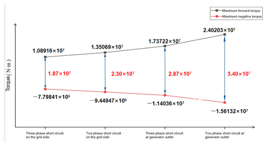
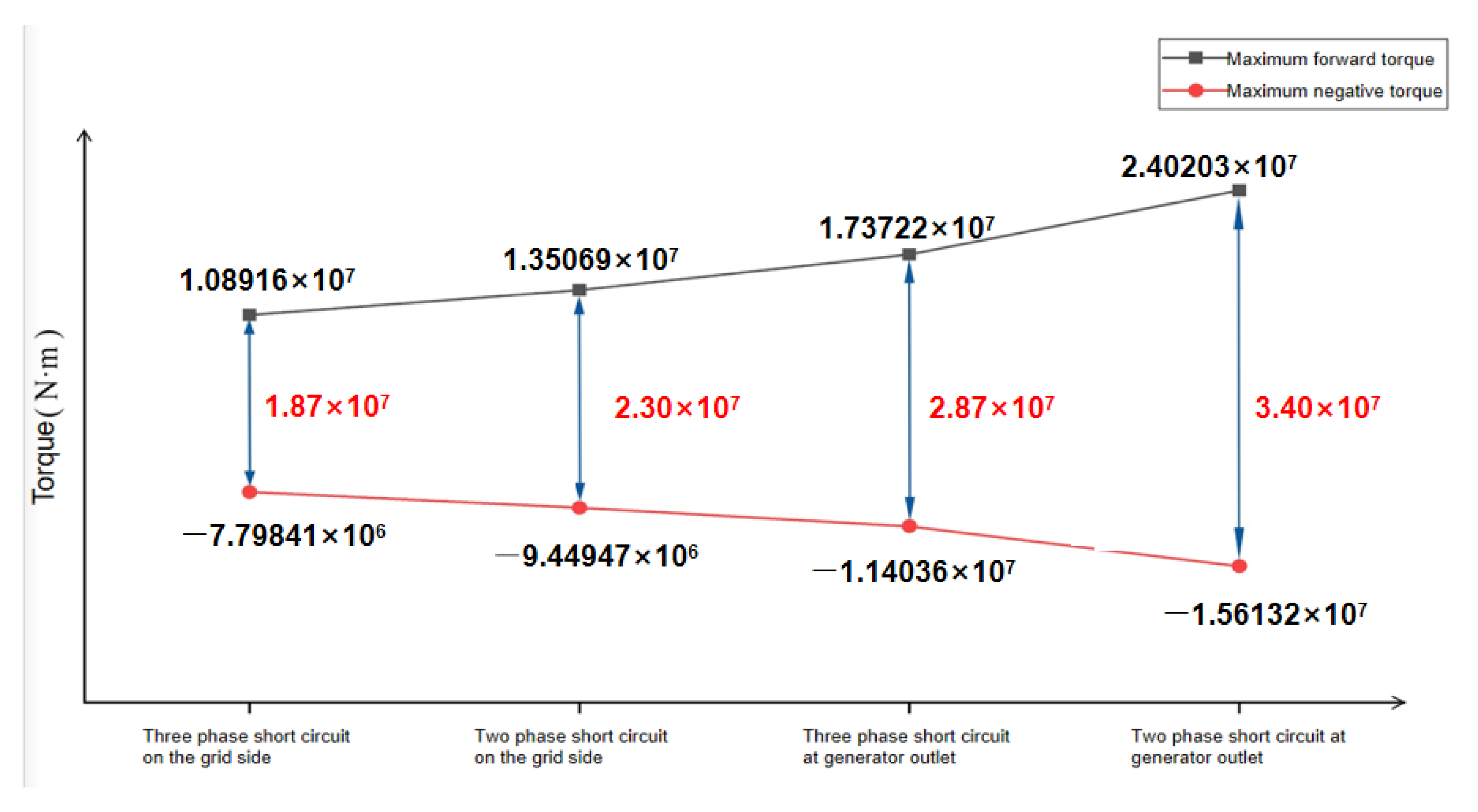
Figure 10.
Maximum alternating electromagnetic impulse torque under different short-circfaults.
It can be seen that the transient electromagnetic alternating impact caused by a two-phase short-circuit fault at the generator terminals is the largest. The transient alternating impact value of the three-phase short-circuit fault on the grid side is the smallest. The transient electromagnetic alternating impact caused by generator terminal short-circuit is greater than the short-circuit fault in the power grid. At the same fault location, the transient electromagnetic impact torque caused by the two-phase short-circuit is greater than that caused by a three-phase short-circuit.
We extracted four short-circuit fault time domains’ (0.2–0.25 s) alternating torque frequencies; as shown in Table 5, the frequency fluctuation range is about 50 Hz (power frequency). In the short-circuit fault analyzed above, the frequency of the transient electromagnetic impact torque precludes the natural frequency of the torsional vibration of shafting. Therefore, in the excitation time domain of four short-circuit faults, the resonance of the torsional vibration of shafting will not occur. After the short-circuit impact fault, the system still needs a period of small-amplitude alternating torque fluctuation to return to the steady state. After the fault is removed, the residual torque fluctuation in the system affects shaft excitation.
Table 5.
Known value under 80% load of generator.
5.2. Short-Circuit Fault Current Analysis
The maximum values of the four kinds of fault current impulse are extracted, and a curve is drawn, as shown in Figure 11.
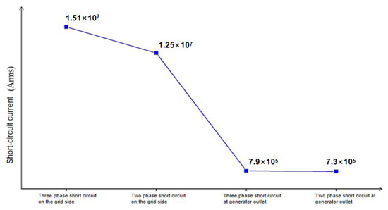
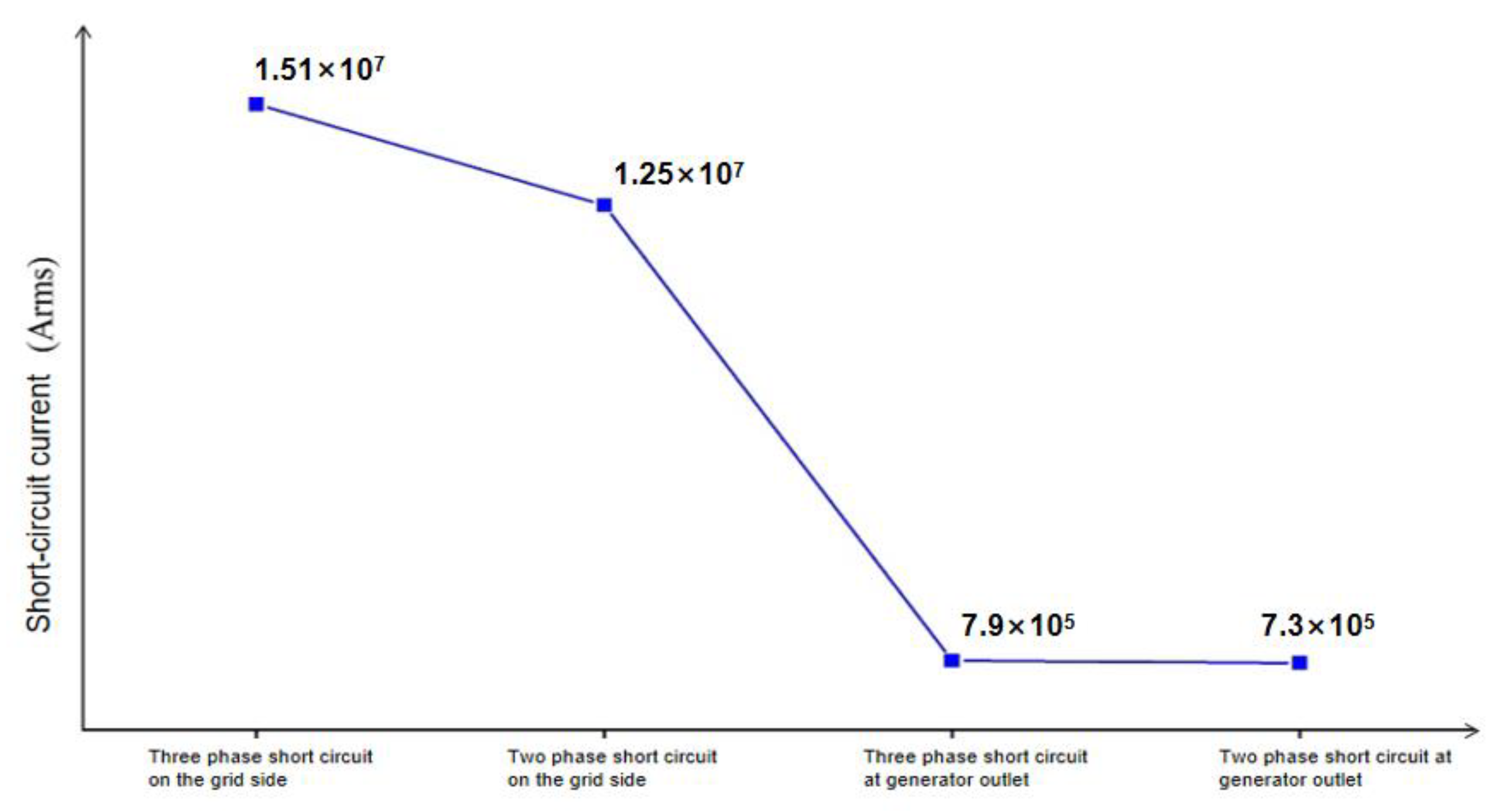
Figure 11.
Maximum impulse current under different short-circuit faults.
The impact current generated by a three-phase short-circuit at different fault locations is greater than that of a two-phase short-circuit, and the impact current generated by the grid’s short-circuit fault is much larger than the impact current generated by the generator terminal’s short-circuit fault. A short-circuit fault occurring near the mechanical power grid has a more severe impact on the power grid than the generator terminal’s short-circuit fault.
5.3. Analysis of Speed Difference at a Low-Frequency Connection of the Short-Circuit Fault
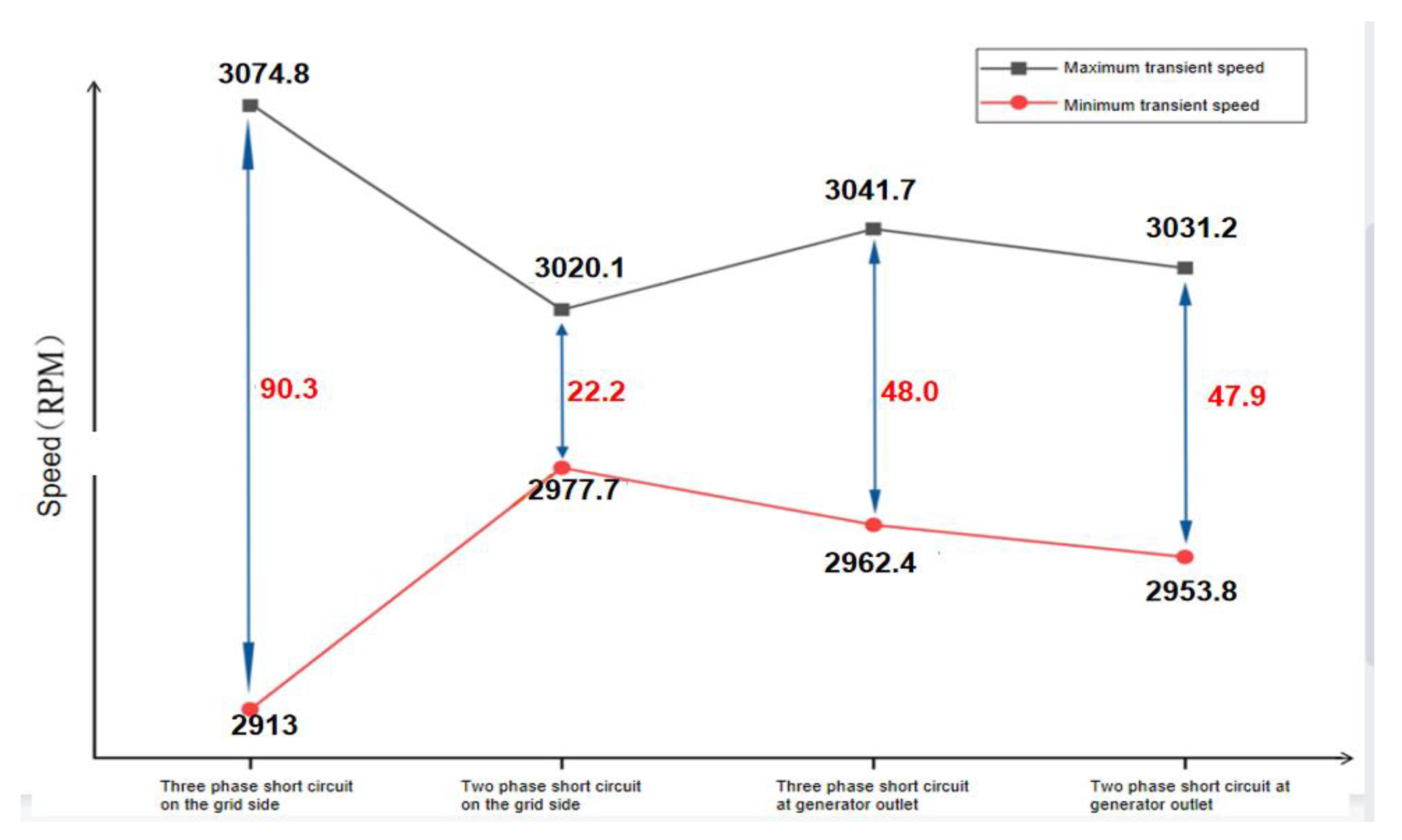
The simulation results of the speed difference between the low-voltage rotor and the generator rotor show that the transient speed difference caused by the three-phase short-circuit on the grid side is the largest, and the transient extremum fluctuation is 74.8 rpm. In contrast, the speed fluctuation caused by the two-phase short-circuit on the grid side is the smallest, and the transient extreme fluctuation is 20 rpm. The velocity fluctuation under the above four short-circuit fault conditions is shown in Table 6, and the corresponding velocity fluctuation curve is shown in Figure 12.
Table 6.
Known value under 80% load of generator.
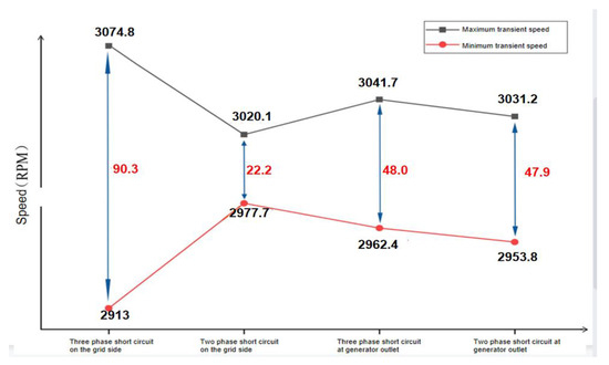
Figure 12.
Speed deviation of steam turbine and generator under different short-circuit faults.
Of the four short-circuit fault conditions affecting the speed fluctuation, the positive speed fluctuation and transient speed difference generated by the grid-side three-phase short-circuit are the largest. The difference between the speed fluctuations caused by the two-phase short-circuit on the grid side and the transient speed is the smallest.
6. Conclusions
Taking a 1000 MW turbo-generator unit as the research object, a system model of a 1000 MW turbo-generator unit based on MATLAB/SIMULINK is built. The ode23tb algorithm is used to simulate and analyze the faults of two-phase and three-phase short-circuits at generator terminals, and two-phase and three-phase short-circuits at the grid side through the synchronous generator module and the multi-mass steam turbine module based on flux linkage equation. The transient electromagnetic impact torque and short-circuit current fluctuation under four fault conditions are extracted and analyzed; the simulation results are close to the actual behavior of the system, providing a database for subsequent research and a reference for fault diagnosis for practical engineering.
- In terms of the transient electromagnetic torque impact value, the two-phase short-circuit fault of the generator terminals was the largest, the three-phase short-circuit fault of the grid side was the smallest, and the electromagnetic torque impact value of the generator terminals under fault was greater than that of the grid side. The transient electromagnetic impact torque caused by a two-phase short-circuit at the same fault point was greater than that caused by a three-phase short-circuit;
- The transient impulse current under three-phase short-circuit at any fault point is greater than that under two-phase short-circuit. The impact current of a grid-side short-circuit fault is much larger than the generator terminals’ short-circuit fault. The speed fluctuation between rotors and the fluctuation difference caused by the three-phase short-circuit on the grid side are the largest;
- Four kinds of fault with transient electromagnetic force alternating frequencies, excluding the natural frequency of the unit shaft torsional vibration, will not give rise to short-circuit fault time domain shaft torsional resonance. However, the potential impact of the residual small fluctuation of torque in the rotor system after the fault is removed needs further analysis.
Author Contributions
Conceptualization, H.P. and T.Z.; methodology, H.P. and Y.W.; software, Y.W.; validation, H.P.; formal analysis, Y.W.; investigation, H.P. and T.Z.; resources, H.P.; data curation, Y.W.; writing—original draft preparation, H.P.; writing—review and editing, Y.W.; visualization, Z.P. and Y.F.; supervision, T.Z.; project administration, Z.P. and T.Z.; funding acquisition, H.P. and T.Z. All authors have read and agreed to the published version of the manuscript.
Funding
This research was funded the National Natural Science Foundation of China, grant number 51805076, U1708255 and 51775093, National Science and Technology Major Project of China, grant number J2019-I-0008-0008, and the Fundamental Research Funds for the Central Universities of China, grant number N2105013; China Postdoctoral Science Foundation, grant number 2019M661125, Doctorate Start Foundation of Liaoning Provincial, grant number 20180540077, Scientific Research Funding Project of Liaoning Education Department, grant number Jl-2003, Science and Technology Program of Shenyang, grant number 20-206-4-16, Science and Technology Innovation Team Support Program of Shenyang middle-aged and young people, grant number RC190342.
Institutional Review Board Statement
Not applicable.
Informed Consent Statement
Not applicable.
Data Availability Statement
Data sharing not applicable.
Conflicts of Interest
The authors declared no conflict of interest.
References
- Song, M.H.; Pham, X.D.; Vuong, Q.D. Torsional Vibration Stress and Fatigue Strength Analysis of Marine Propulsion Shafting System Based on Engine Operation Patterns. J. Mar. Sci. Eng. 2020, 8, 613. [Google Scholar] [CrossRef]
- Rajkiran, U.; Vinoth, A.; Jegadeesan, K.; Shravankumar, C. Lateral and torsional vibration analysis of composite shaft. IOP Conf. Ser. Mater. Sci. Eng. 2020, 912, 022040. [Google Scholar] [CrossRef]
- Chow, J.H.; Javid, S.H.; Sanchez-Gasca, J.J.; Bowler, C.E.J.; Edmonds, J.S. Torsional model identification for turbine-generators. IEEE Trans. Energy Convers. 1986, 4, 83–91. [Google Scholar] [CrossRef]
- Fairbairn, R.E.; Jennings, G.D.; Harley, R.G. Turbogenerator torsional mechanical modal parameter identification from on-line measurements. IEEE Trans. Power Syst. 1991, 6, 1389–1395. [Google Scholar] [CrossRef]
- Li, Z.Y.; Tian, S.J.; Zhang, Y.F.; Li, H.; Lu, M. Active Control of Drive Chain Torsional Vibration for DFIG-Based Wind Turbine. Energies 2019, 12, 1744. [Google Scholar] [CrossRef] [Green Version]
- Masayuki, W.; Hiroyuki, I.; Kazuma, S.; Yasunori, M.; Yoshihisa, U.; Yoshihide, K. Analysis of Turbine Generator Shaft Torsional Vibration Caused by Self-Commutated Converters. Electr. Eng. Jpn. 2015, 193, 9–17. [Google Scholar]
- Masayuki, W.; Ueno, Y.; Yasunori, M.; Hiroyuki, I.; Yoshihisa, U.; Yasuhiro, U. A Dynamical Model for Customer’s Gas Turbine Generator in Industrial Power Systems. IFAC Proc. Vol. 2009, 42, 203–208. [Google Scholar]
- Tang, G.J.; Chen, X.J. Analysis of torsional vibration inherent characteristics of rotating machinery shafting. Steam Turbine Technol. 2010, 52, 339–341, 344. [Google Scholar]
- Zhao, T.Y.; Cui, Y.S.; Pan, H.G.; Yuan, H.Q.; Yang, J. Free vibration analysis of a functionally graded graphene nanoplatelet reinforced disk-shaft assembly with whirl motion. Int. J. Mech. Sci. 2021, 197. [Google Scholar] [CrossRef]
- Zhao, T.Y.; Yuan, H.Q.; Yang, W.J.; Sun, H.G. Genetic particle swarm parallel algorithm analysis of optimization arrangement on mistuned blades. Eng. Optim. 2017, 49, 2095–2116. [Google Scholar] [CrossRef]
- Zhao, T.Y.; Jiang, Z.Y.; Zhao, Z.; Xie, L.Y.; Yuan, H.Q. Modeling and free vibration analysis of rotating hub-blade assemblies reinforced with graphene nanoplatelets. J. Strain Anal. Eng. Des. 2021. [Google Scholar] [CrossRef]
- Liu, J.H.; Huang, S.H.; Lu, J.D. Dynamic frequency study on torsional vibration of large turbo-generator shaft. Therm. Power Eng. 2005, 3, 234–238, 328–329. [Google Scholar]
- Liu, J.H.; Huang, S.H.; Lu, J.D. Research on torsional vibration frequency of single mass disk rotor. J. Huazhong Univ. Sci. Technol. (Nat. Sci. Ed.) 2005, 8, 12–15. [Google Scholar]
- Liu, J.H.; Huang, S.H.; Lu, J.D. Dynamic frequency problem of torsional vibration of turbine mechanical shafting. Shanghai Steam Turbine 2003, 4, 237–239. [Google Scholar]
- Zhao, T.Y.; Ma, Y.; Zhang, H.Y.; Pan, H.G.; Cai, Y. Free vibration analysis of a rotating graphene nanoplatelet reinforced pre-twist blade-disk assembly with a setting angle. Appl. Math. Model. 2021, 93, 578–596. [Google Scholar] [CrossRef]
- Zhao, T.Y.; Jiang, L.P.; Pan, H.G.; Yang, J.; Sritawat, K. Coupled free vibration of a functionally graded pre-twisted blade-shaft system reinforced with graphene nanoplatelets. Compos. Struct. 2020, 262, 113362. [Google Scholar] [CrossRef]
- Zhao, T.Y.; Ma, Y.; Zhang, H.Y.; Yang, J. Coupled Free Vibration of Spinning Functionally Graded Porous Double-Bladed Disk Systems Reinforced with Graphene Nanoplatelets. Materials 2020, 13, 5610. [Google Scholar] [CrossRef]
- Pan, H.G.; Wu, Y.S.; Zhao, T.Y. Study on Influence of Multi-Parameter Variation of Bladed Disk System on Vibration Characteristics. Appl. Sci. 2021, 11, 3084. [Google Scholar] [CrossRef]
- Pan, H.G.; Wu, Y.S.; Zhou, J.N.; Fu, Y.M.; Liang, X.; Zhao, T.Y. Free Vibration Analysis of a Graphene-Reinforced Porous Composite Plate with Different Boundary Conditions. Materials 2021, 14, 3879. [Google Scholar] [CrossRef]
- Kundur, P.; Paserba, J.; Ajjarapu, V.; Goran, A.; Anjan, B.; Claudio, C.; Nikos, H.; David, H.; Alex, S.; Carson, T.; et al. Definition and Classification of Power System Stability. IEEE Trans. Power Syst. 2004, 19, 1387–1401. [Google Scholar]
- Mazana, A.; Jose, R.M.; Luis, R.L.; Kundur, P. Multilevel MATE for Efficient Simultaneous Solution of Control Systems and Nonlinearities in the OVNI Simulator. IEEE Trans. Power Syst. 2006, 21, 1250–1259. [Google Scholar]
- Venkata, S.S.; Sukumar, B.; Jason, S.; Kundur, P. Continue Your Learning. IEEE Power and Energy Mag. 2010, 8, 36–43. [Google Scholar] [CrossRef]
- Zhao, T.Y.; Cui, Y.S.; Wang, Y.Q.; Pan, H.G. Vibration characteristics of graphene nanoplatelet reinforced disk-shaft rotor with eccentric mass. Mech. Adv. Mater. Struct. 2021, 1–21. [Google Scholar] [CrossRef]
- Zhao, T.Y.; Yang, Y.F.; Pan, H.G.; Zhang, H.Y.; Yuan, H.Q. Free vibration analysis of a spinning porous nanocomposite blade reinforced with graphene nanoplatelets. J. Strain Anal. Eng. Des. 2021, 56, 574–586. [Google Scholar] [CrossRef]
- Zhao, T.Y.; Liu, Z.F.; Pan, H.G.; Zhang, H.Y.; Yuan, H.Q. Vibration Characteristics of Functionally Graded Porous Nanocomposite Blade-disk-shaft Rotor System Reinforced with Graphene Nanoplatelets. Appl. Compos. Mater. 2021, 28, 717–731. [Google Scholar] [CrossRef]
- Zhao, T.Y.; Wang, Y.X.; Yu, Y.X.; Cai, Y.; Wang, Y.Q. Modeling and vibration analysis of a spinning assembled beam–plate structure reinforced by graphene nanoplatelets. Acta Mech. 2021, 1–17. [Google Scholar] [CrossRef]
- Zhao, T.Y.; Wang, Y.X.; Pan, H.G.; Yuan, H.Q.; Cai, Y. Nonlinear forced vibration analysis of spinning shaft-disk assemblies under sliding bearing supports. Math. Methods Appl. Sci. 2020. [Google Scholar] [CrossRef]
- Zhao, T.Y.; Wang, X.Y.; Pan, H.G.; Gao, X.S. Analytical solution for vibration characteristics of rotating graphene nanoplatelet-reinforced plates under rub-impact and thermal shock. Adv. Compos. Lett. 2020, 29. [Google Scholar] [CrossRef]
- Zhao, T.Y.; Li, H.G.; Sun, H.G. Parallel intelligent algorithm analysis of optimization arrangement on mistuned blades based on compute unified device architecture. Proc. Inst. Mech. Eng. Part G J. Aerosp. Eng. 2018, 233, 2207–2218. [Google Scholar] [CrossRef]
- Li, Z.J.; Zhao, T.Y.; Kou, H.J.; Zhang, H.; Yuan, H.Q. Vibration characteristics of multi-stage blade–disk–shaft integrated structure with three-dimensional crack. J. Vib. Eng. Technol. 2021, 9, 597–611. [Google Scholar] [CrossRef]
- Kacejko, P.; Machowski, J. Modelling of phase shifting transformers in short circuit calculations. Prz. Elektrotechniczny 2017, 93, 1–5. [Google Scholar]
- Gryszpanowicz, K.; Machowski, J.; Robak, S. Overload emergency state control of transmission network based on generation curtailment. Prz. Elektrotechniczny 2016, 92, 275–280. [Google Scholar]
- Navid, A.; Seyyedmilad, E.; Juri, J.; Hermann, W.D. Saturable and Decoupled Constant-Parameter VBR Model for Six-Phase Synchronous Machines in State-Variable Simulation Programs. IEEE Trans. Energy Convers. 2019, 34, 1868–1880. [Google Scholar]
- Navid, A.; Seyyedmilad, E.; Mehrdad, C.; Juri, J.; Hermann, W.D. Constant-Parameter Voltage-Behind-Reactance Model of Six-Phase Synchronous Machines. IEEE Trans. Energy Convers. 2017, 32, 548–559. [Google Scholar]
- Navid, A.; Seyyedmilad, E.; Mehrdad, C.; Juri, J.; Hermann, W.D. Voltage-behind-reactance model of six-phase synchronous machines considering stator mutual leakage inductance and main flux saturation. Electr. Power Syst. Res. 2016, 138, 155–164. [Google Scholar]
- Zhao, T.Y.; Li, G.B.; Pan, H.G.; Yuan, H.Q. Dynamic characteristics analysis for vehicle parts based on parallel optimization algorithm with CUDA. Eng. Comput. 2021, 38, 3622–3642. [Google Scholar] [CrossRef]
- Cai, Y.; Liu, Z.F.; Zhao, T.Y.; Yang, J. Parameter Interval Uncertainty Analysis of Internal Resonance of Rotating Porous Shaft–Disk-Blade Assemblies Reinforced by Graphene Nanoplatelets. Materials 2021, 14, 5033. [Google Scholar] [CrossRef]
- Sun, H.T. Discussion on shafting torsional vibration of large turbo-generator sets. Therm. Power Gener. 2004, 1, 42–44; 54–88. [Google Scholar]
- Kimbark, E.W. Correction of IEEE Published Paper Suppression of Ground-Fault Arcs on Single-Pole-Switched EHV Lines bv Shunt Reactors. IEEE Power Eng. Rev. 1986, 6, 25. [Google Scholar] [CrossRef]
- Kimbark, E.W. Experimental analysis of double unbalances. Electr. Eng. 1935, 54, 205. [Google Scholar] [CrossRef]
- Kimbark, E.W. How to improve system stability without risking subsynchronous resonance. IEEE Trans. Energy Convers. 1977, 96, 1608–1619. [Google Scholar] [CrossRef]
- Kimbark, E.W. Power System Stability [Books and Reports]. IEEE Power Eng. Rev. 1995, 15, 40. [Google Scholar] [CrossRef]
- Dome, R.B. High-Efficiency Modulation System. Proc. IEEE 1938, 26, 963–982. [Google Scholar] [CrossRef]
- Ghasemi, S.; Allahbakhshi, M.; Behdani, B.; Tajdinian, M.; Popov, M. Probabilistic analysis of switching transients due to vacuum circuit breaker operation on wind turbine step-up transformers. Electr. Power Syst. Res. 2020. [Google Scholar] [CrossRef]
- Isidoro, G.; Gustavo, S.A. Delta-Wye Transformations and the Efficient Reduction of Almost-Planar Graphs. Electron. Notes Discret. Math. 2017, 62, 129–134. [Google Scholar]
- Isidoro, G.; Gustavo, S.A. An algorithm for delta–wye reduction of almost-planar graphs. Discret. Appl. Math. 2020, 285, 631–641. [Google Scholar]
- Juan, L.; Duarte, M.; Ospina, H.; González, Q. Dynamic Modeling and Simulation of an Underactuated System. J. Phys. Conf. Ser. 2017, 850, 012005. [Google Scholar]
- Duart, J.L.; Montero, B.; Ospina, P.A.; González, E. Dynamic Modeling and Simulation of a Rotational Inverted Pendulum. J. Phys. Conf. Ser. 2017, 792, 012081. [Google Scholar] [CrossRef] [Green Version]
- Fan, Y.F.; Lin, H. Application of MATLAB/SIMULINK in power system simulation. J. Xinjiang Univ. (Nat. Sci. Ed.) 2004, 2, 205–207. [Google Scholar]
- Rehman, A.U.; Chen, Y.; Wang, L. Simulation using MATLAB/SIMULINK on rotor winding inter-turn fault in DFIG/2016 IEEE International Conference on Dielectrics (ICD). IEEE 2016, 1, 506–509. [Google Scholar]
- Jiang, J.; Li, W.F.; Wang, X.J.; Sun, Q.; Wei, Q. Modal analysis of shaft system and spring foundation of turbine-generator unit model based on substructure method. Steam Turbine Technol. 2018, 60, 123–126. [Google Scholar]
- Liang, P.; Fan, L.L.; Long, X.F. The application of nonlinear model in vibration fault prediction of turbine generator sets. J. South China Univ. Technol. (Nat. Sci. Ed.) 2006, 6, 122–126. [Google Scholar]
- He, C.B.; Gu, Y.J.; Yang, K. Overview of torsional vibration model and algorithm of turbo-generator set. J. North China Electr. Power Univ. 2003, 2, 56–60. [Google Scholar]
- Wang, N.; Liang, Z.Q. The transfer matrix calculation method of natural frequency of rotor system and its MATLAB implementation. J. Sichuan Univ. Technol. (Nat. Sci. Ed.) 2006, 2, 55–59. [Google Scholar]
- Nazolin, A.L.; Polyakov, V.I.; Gnezdilov, S.G. Diagnostics of Shaft Trains of Large Turbine Sets for Integrity Using Torsional Vibration Measurements. Therm. Eng. 2020, 67, 25–35. [Google Scholar] [CrossRef]
- Briz, F.; Degner, M.W.; Lorenz, R.D. Analysis and design of current regulators using complex vectors. IEEE Trans. Ind. Appl. 2000, 36, 817–825. [Google Scholar] [CrossRef] [Green Version]
- Arumuga, T.; Muthukumar, D.; Saji, K.S. Matlab Simulation for Fault Analysis of Electrical Circuit on Hyperspectral Signal Processing. Int. J. Eng. Adv. Technol. (IJEAT) 2019, 9, 343–350. [Google Scholar]


Publisher’s Note: MDPI stays neutral with regard to jurisdictional claims in published maps and institutional affiliations. |
© 2021 by the authors. Licensee MDPI, Basel, Switzerland. This article is an open access article distributed under the terms and conditions of the Creative Commons Attribution (CC BY) license (https://creativecommons.org/licenses/by/4.0/).