Abstract
It is difficult to measure elastic modulus simply and accurately in the testing of mechanical properties of materials. Combined with static tensile method, this paper presents a method for measuring elastic modulus of materials based on air-coupled ultrasonic nondestructive testing. Firstly, the 1–3 piezoelectric composite material and the matching material of low acoustic impedance are self-made, and 400 kHz air-coupled ultrasonic transducer is fabricated. Then, the performance of the transducer is tested, and the insertion loss and bandwidth of −6 dB are −33.5 dB and 23.4%, respectively. Compared with the traditional instrument for measuring elastic modulus, the measurement of elastic modulus of carbon steel rod material is realized in this paper, and the measured results are in agreement with the accepted value. In addition, from the angle of relative uncertainty, how to reduce the measurement error by improving the device is analyzed. It can be shown that the method has high linearity, high symmetry, and good stability and repeatability. This paper provides a new way for the selection and design of measuring instrument components.
1. Introduction
Within the elastic limit, the stress and strain of an elastic body become directly proportional, and its ratio is called elastic modulus, also known as Young’s modulus or tensile modulus. Macroscopically, elastic modulus indicates the ability of solid material to resist deformation. Microscopically, the elastic modulus reflects the strength of the bond between atoms. In engineering application, the elastic modulus of materials plays an important role in the application, modification and microstructure study of materials. No matter studying the static or dynamic characteristics of mechanical components [1], the measurement of elastic modulus is of great significance for studying the mechanical properties, state and life of materials [2,3]. The size of elastic modulus is related to the type of material, temperature and other factors [4]. With the continuous progress of technology, all kinds of machinery and precision instruments have higher and higher requirements for the mechanical properties of materials, which put forward higher requirements for accurately measuring the elastic modulus of different materials in different application environments.
In general, both the resonance method and the static method can measure the elastic modulus of the material [5,6,7]. Resonance method is suitable for measuring samples with large elastic modulus, and can also be applied to measure the elastic modulus of materials at high temperature [8,9]. In 2013, Bahr O et al. [10] used the resonance method to measure the elastic modulus of fireproof concrete materials at different temperatures, and re-established the relationship curve between the characteristics of high-temperature fireproof materials and temperature changes. In 2019, Gregorova E et al. [11] measured the change of elastic modulus of aluminum ceramic materials during heating and cooling. The static method is suitable for measuring materials with large elongation, but it is difficult to measure brittle materials and materials at different temperatures. The key of this method is to detect the micro-shape of material caused by external force. At present, the measurement methods of material microform variables mainly include optical measurement, electrical measurement and so on. Optical measurement methods [12,13,14,15,16,17,18,19] include optical lever method [12], diffraction method [13,14], digital optical speckle method [15,16], etc. The principle of electrical measurement is that when the size of metal material changes, its resistance value also changes. In this way, by measuring the change of resistance, the micro-shape variable of the sample can be calculated. Because electrical measurement depends on the conductivity of the material, this method is only suitable for metal materials. In contrast, the static tensile test device used in this paper has the advantages of simple structure and operation, stable performance and high precision. It has wide application value in designing all kinds of testing instruments.
Ultrasonic testing is an important nondestructive testing technology. It can evaluate the properties and defects of materials [20,21,22] by detecting the changes of reflected or transmitted ultrasonic wave signals. Parveen N et al. [23] detected the creep characteristics of Nimonic C263, and analyzed the creep deformation behavior and fracture mechanism of nickel-based superalloy. Xia et al. [24] used ultrasonic phased array method to measure the propagation velocity of ultrasonic in brass, and then calculated the elastic modulus of brass. Dalibor Kocab et al. [25] measured the static and dynamic elastic moduli of AAS composites, and carried out ultrasonic characterization of the elastic moduli and compressive strength properties of the materials.
The traditional ultrasonic testing technology needs to fill the coupling agent between the ultrasonic transducer and the sample to realize the effective propagation of acoustic signal when measuring elastic modulus. However, the existence of coupling agent limits the application of static stretching method, which requires a new ultrasonic nondestructive testing [26,27,28,29]. With the rapid development of air-coupled ultrasonic transducer preparation technology [30,31,32,33], air-coupled ultrasonic non-destructive testing technology, which is completely non-contact and non-invasive, has gradually become a research hotspot [34,35]. In this paper, a high-performance flat type air-coupled ultrasonic transducer is designed and fabricated by using homemade 1–3 piezoelectric composite material and double matched layer structure, and its performance is tested and characterized. On this basis, the elastic modulus of carbon steel rod material is effectively measured. Furthermore, how to improve the accuracy of elastic modulus measurement to reduce the measurement error is discussed from the angle of influencing the relative uncertainty.
2. Design of High-Performance Flat Air-Coupled Ultrasonic Transducer
Piezoelectric ultrasonic transducer is a kind of device which realizes the conversion of electrical energy and mechanical energy based on the piezoelectric effect and inverse piezoelectric effect of piezoelectric materials. The key problem in the design of high-performance air-coupled ultrasonic transducer is how to effectively solve the acoustic impedance mismatch between the piezoelectric material and the transmission medium air.
In this paper, the 1–3 piezoelectric composite material and matching materials of low voice impedance are self-made, and the optimization design of matching layer thickness of air-coupled ultrasonic transducer with double matching layer structure is completed.
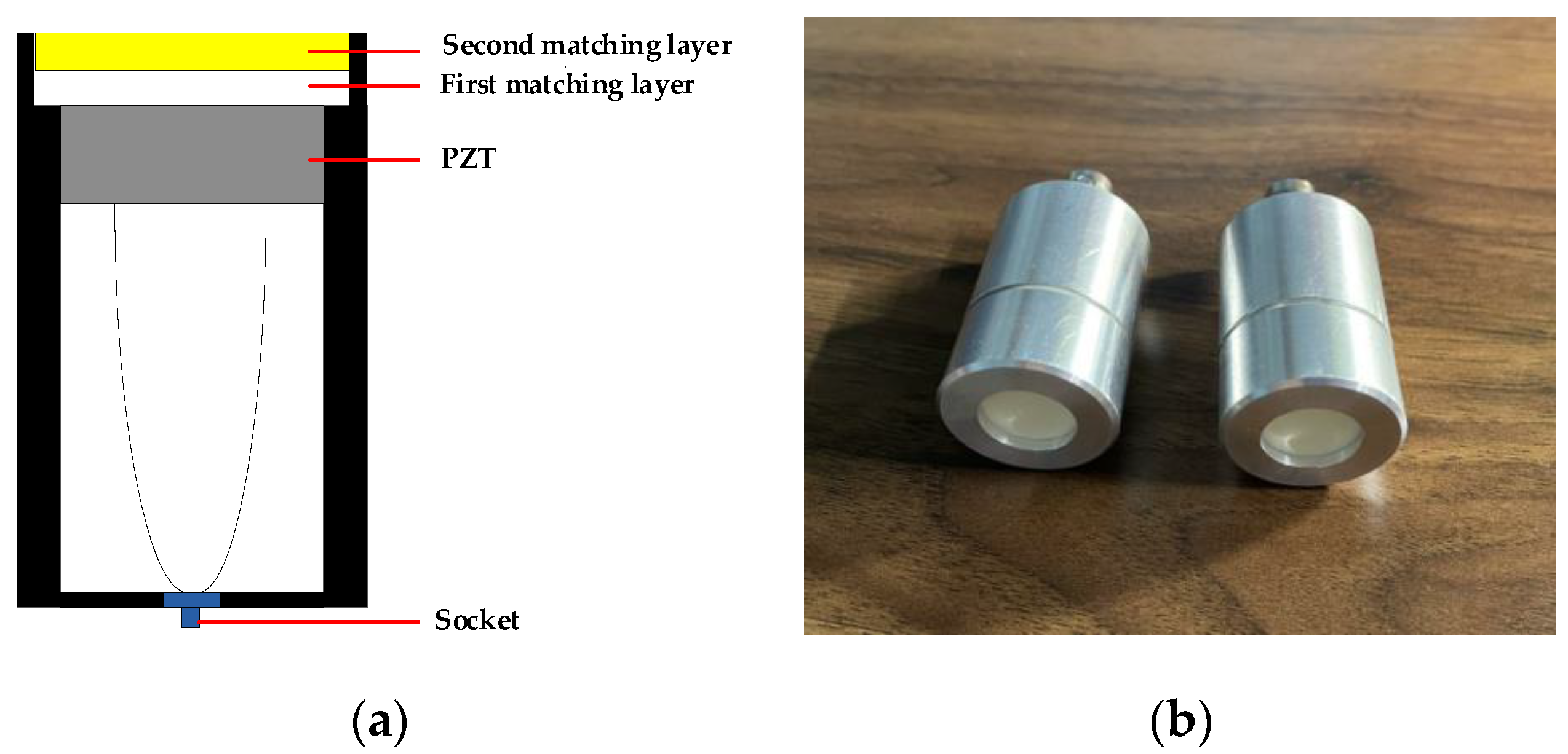
In Figure 1, the 1–3 piezoelectric composite vibrator selected in this paper has a radius of 6.5 mm, a thickness of 3.2 mm, and a piezoelectric ceramic column size of 1.6 * 1.6 * 3.2 mm3. The Matching Layer 1 material is a polymer of hollow glass beads and epoxy resin, which is self-developed by mixing epoxy resin and hollow glass beads in a certain proportion. This polymer has low acoustic attenuation coefficient and low acoustic impedance, and its characteristics (such as density, acoustic velocity, etc.) parameters can be adjusted (by adjusting the proportion and diameter of hollow glass beads, etc.), so it is an ideal matching material for piezoelectric air-coupled ultrasonic transducer. The material of Matching Layer 2 is a low density porous material purchased. The specific parameters of matched materials are shown in Table 1.

Figure 1.
Schematic diagram (a) and physical diagram (b) of air-coupled ultrasonic transducer.

Table 1.
Physical parameters of the matched material.
Compared with the acoustic impedance characteristics of the matching material, the thickness of the matching layer has a more significant impact on the matching effect [36]. In practical application, the thickness of the quarter wavelength matching layer is not the best matching layer thickness, which needs to be obtained through experiments on the basis of theoretical calculation. The optimal matching layer thicknesses of Matching Layer 1 and Matching Layer 2 obtained by this method are 1.24 mm and 0.50 mm respectively, and a 400 kHz air-coupled ultrasonic transducer with a diameter of 13 mm is designed.
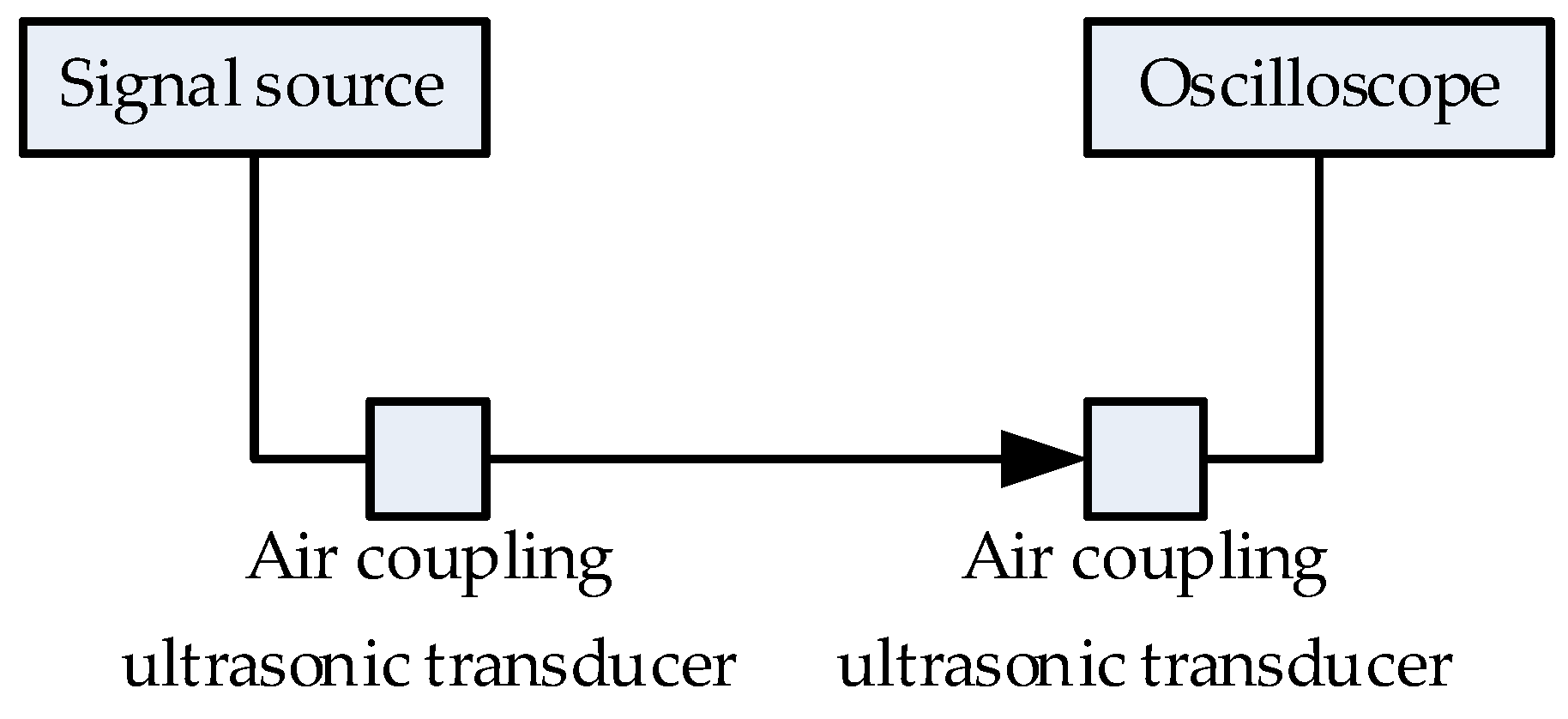
The performance of the transducer is evaluated by using the one-shot, one-take mode. Specifically, a Tek TDS3012C oscilloscope is used to test the reflected or transmitted signals without the use of a power amplifier by stimulating a single square wave signal at the same operating frequency as the air-coupled ultrasonic transducer from the signal source RIGOL DG1022Z. During the test, the transmitting voltage is 10 Vpp and the length of the air column between the transmitting/receiving ultrasonic transducers is 50 mm. The schematic diagram of the test equipment and its results are shown in Figure 2 and Figure 3 respectively.
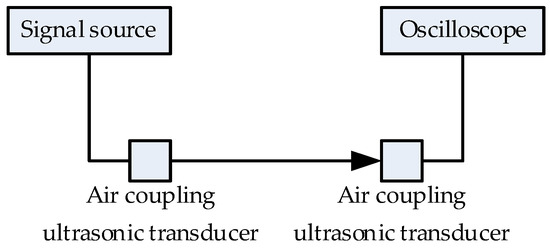
Figure 2.
Schematic diagram of one-shot, one-take mode test.

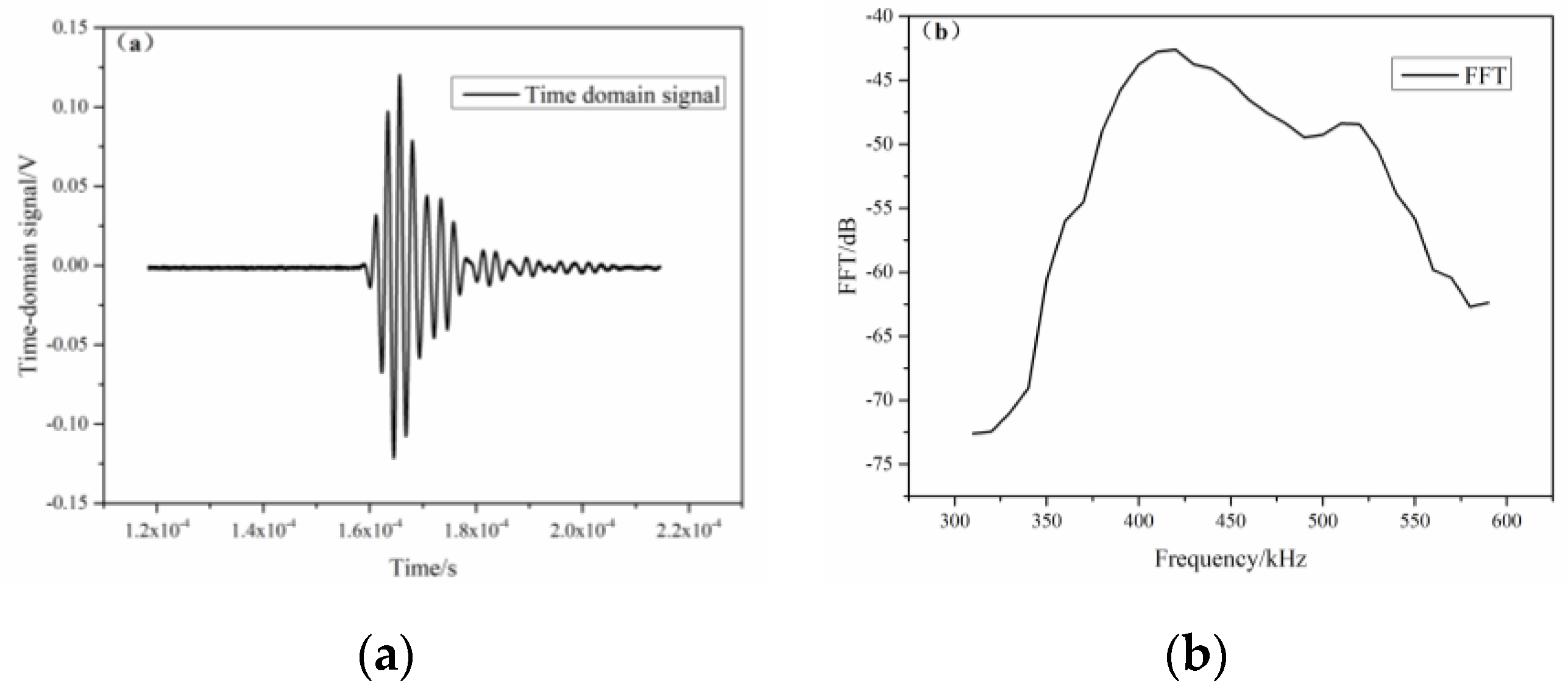
Figure 3.
The test results of air-coupled ultrasonic transducer are shown in the figure. (a) Time domain signals; (b) frequency domain signal.
In addition, Equations (1) and (2) are used to calculate the insertion loss and 6 dB bandwidth.
Among them, is the peak-to-peak value of the pulse-echo signal received by the ultrasonic transducer, and is the peak-to-peak value of the excitation voltage applied to the ultrasonic transducer. and are the high frequency point and low frequency point corresponding to the maximum peak drop of 6dB in the frequency domain respectively, and is the working frequency of the ultrasonic transducer. Finally, the insertion loss and −6 dB bandwidth are calculated to be −33.5 dB and 23.4%, respectively.
3. Measurement of Elastic Modulus of Materials Based on Air-Coupled Ultrasonic Nondestructive Testing
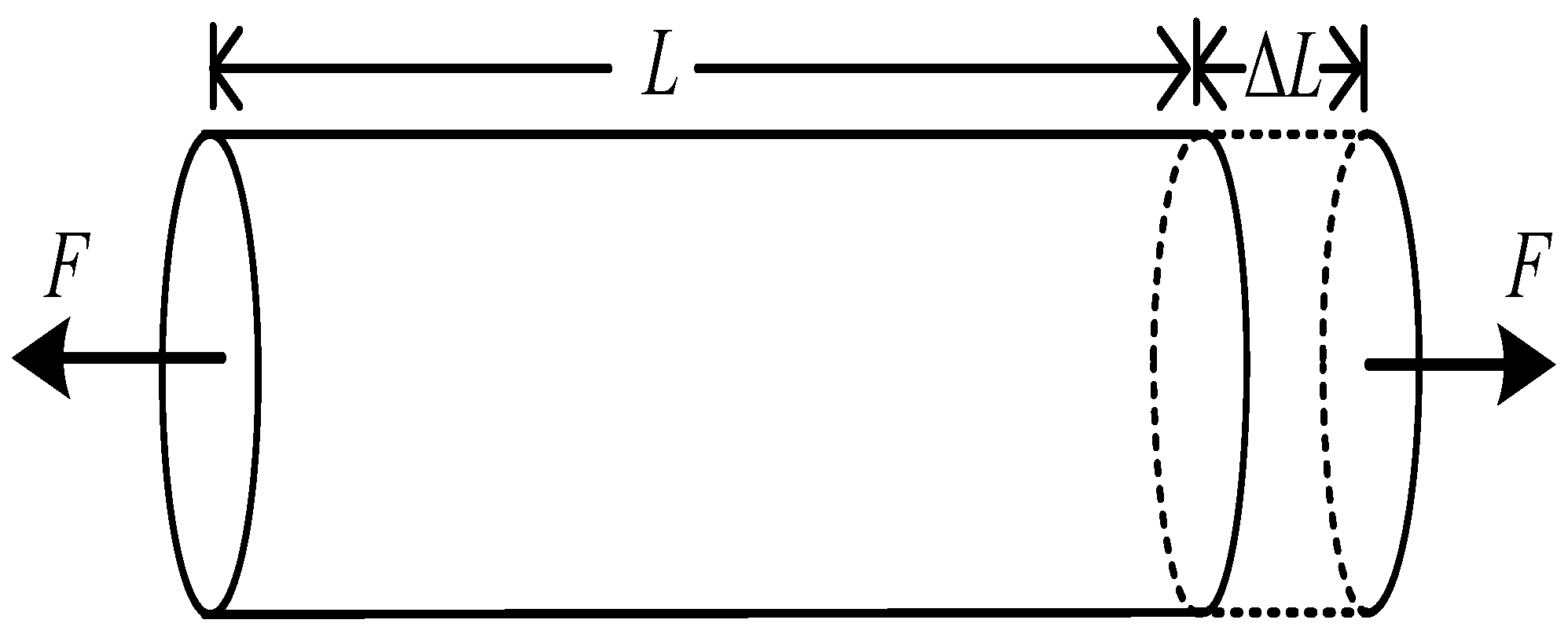
Based on static tensile method, the elastic modulus is tested. As shown in Figure 4, the bar object will be elongated or shortened by external force along the length direction, that is, deformation occurs.
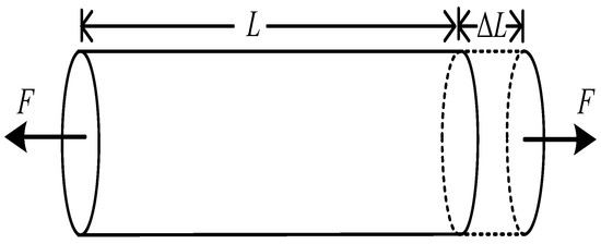
Figure 4.
Schematic diagram of the deformation of a bar when subjected to external forces along the length direction.
Let the cross-sectional area of the wire be S and the length be L. The bar is extended ΔL by an external force F applied along its length. Within the elastic limit of a body, according to Hooke’s law:
In Equation (3), the proportional coefficient E is the elastic modulus of the material, which depends only on the nature of the material itself and has nothing to do with F, L and S. L is measured by general measuring tools such as meter stick and tape measure, F is measured by digital tension sensor, and S can be obtained by measuring its diameter d.
After substituting for Equation (3), it becomes:
In Equation (4), the micro-shaped variable ΔL is measured by a high frequency air-coupled ultrasonic transducer. In order to reduce the measurement error, the minimum step size can be set as half of the wavelength corresponding to the working frequency of the transducer in the specific measurement. If the measurement step is n half-wavelength, then:
After substituting Equation (5) into Equation (4), we obtain:
4. Experimental Results and Analyses
4.1. Deployment of the Experimental Environment
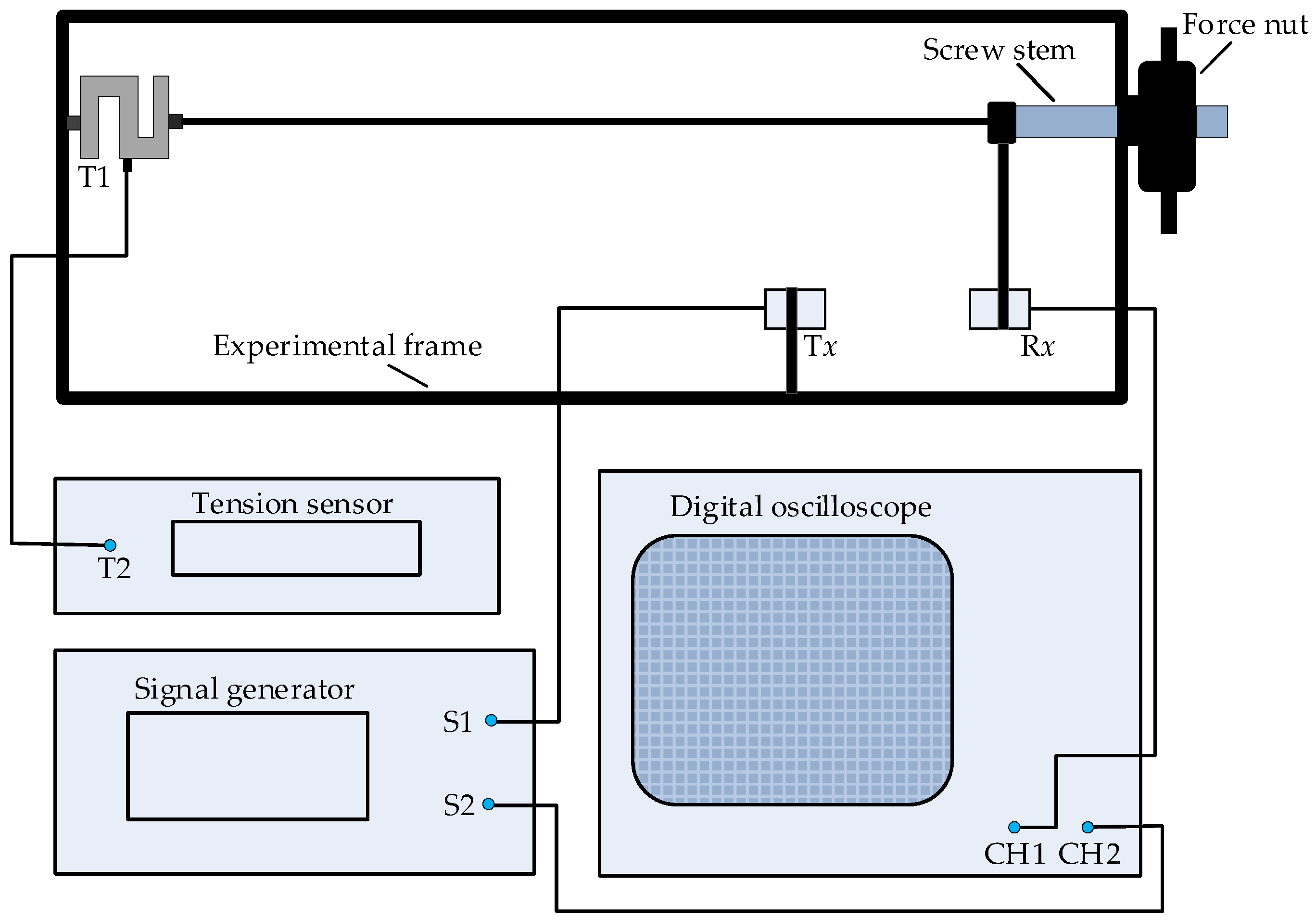
The schematic diagram of elastic modulus measurement is shown in Figure 5, which includes experimental frame, tension sensor, air-coupled ultrasonic transducer, dual-channel signal generator and digital oscilloscope.

Figure 5.
Schematic diagram of an instrument for measuring elastic modulus of materials.
In Figure 5, the experimental frame is the main platform for the measurement of elastic modulus. In the frame, one end of the sample is clamped by the left chuck, and is connected with the tension sensor T1 fixed on the frame, the other end is clamped by the right chuck, and is connected with the screw through the frame. The screw is fitted with a force nut. The nut adopts rotating force to apply external force, which is simple, intuitive and stable. The digital tension meter T2 shows the tension value of the sample under test. This method is simple, intuitive and stable to apply after-force. The air-coupled ultrasonic transducers Tx and Rx are fixed on the frame and the screw and kept horizontally aligned. Among them, the transducer Tx is connected with S1 channel on the double-channel signal generator, the transducer Rx is connected with the digital oscilloscope CH1, and the signal generator S2 channel is connected with the digital oscilloscope CH2.
Specifically, sine continuous wave signals of 400kHz and 3Vpp are added to signal generator S1 and S2 channels at the same time, and the transmitting transducer Tx converts the sine wave signals from signal generator S1 channel into ultrasonic signals of the same frequency. After converting the received acoustic signal into sinusoidal signal by receiving transducer Rx, the results are displayed by digital oscilloscope CH1 channel. At the same time, the sine wave signal from S2 channel of signal generator is displayed through CH2 channel of digital oscilloscope.
Next, the ultrasonic wave from Tx travels through the medium to Rx. At this point, there is a certain phase difference between the transmitted signal and the received signal. As shown in Figure 6, is the phase difference between the two. By changing the distance between Tx and Rx, the change of can be observed.
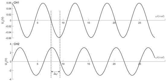
Figure 6.
The phase difference pattern of two harmonic vibrations.
The relationship between phase difference and angular frequency , propagation time , acoustic speed , distance between Tx and Rx, and wavelength is as follows:
According to Equation (7), to change the phase difference by πphases, the distance must change correspondingly by half wavelength /2. For the phase difference to change by 2π phases, the distance must change by a corresponding wavelength .
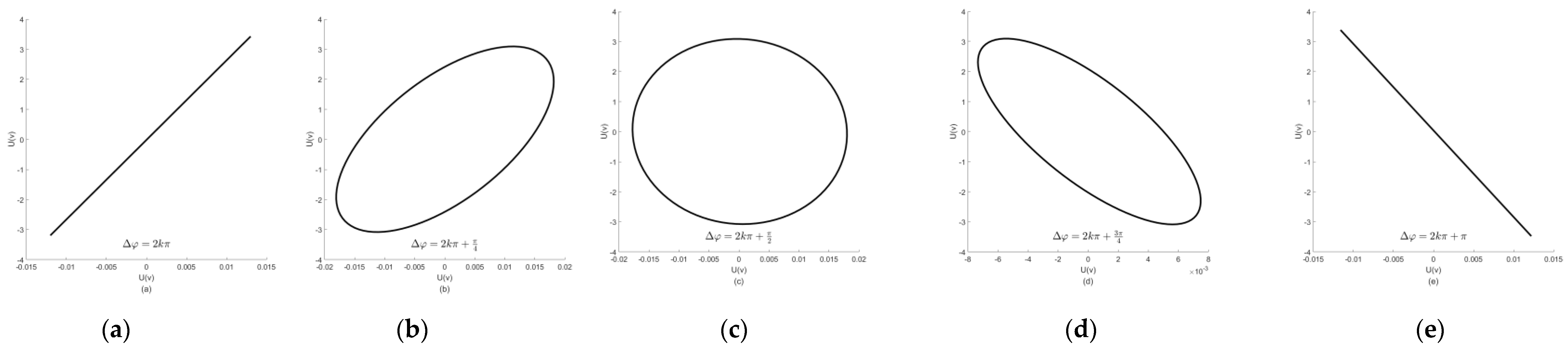
Set the operation mode of the oscilloscope to ‘X-Y’, then the transmitted and received waves are added to the ‘X’ and ‘Y’ deflector plates of the oscilloscope respectively. In this way, the two harmonic oscillations are superimposed vertically to each other to form the Lissajous—Figure on the fluorescent screen. If we move Rx continuously in the same direction, then changing the distance between Tx and Rx will change the phase difference between the two vibrations. When the phase difference of the two vibrations changes from 0 to π, it can be seen on the screen that the graph changes from a positive straight line to an ellipse and then to a negative straight line, as shown in Figure 7. Here, the elongation of the sample material ΔL is equal to /2.
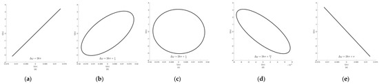
Figure 7.
Lissajous—Figure for a specific phase difference. (a) ; (b) ; (c) ; (d) ; (e) .
In Figure 7, k is a natural number. Before the experiment, a tension of about 20 N is applied on the sample metal wire to straighten the metal wire where it might have been bent, and then the force nut is adjusted until the oscilloscope displays the figure as shown in Figure 7a. At this point, the tension value displayed by the tension sensor is recorded and the wire elongation ΔL is recorded as 0. We slowly rotate the force nut again, increase the tension on the sample, and make the receiving transducer Rx move /2 until the oscilloscope displays the graph as shown in Figure 7e. Next, the tension sensor value is recorded again. This is repeated until the receiving transducer Rx moves to 5/2. After the tension is slowly increased at about 2N, the nut is slowly rotated in the opposite direction to reduce the force. Count from the receiving transducer Rx moving to 5/2. Each time the wavelength /2 of Rx are moved, a group of data is recorded until ΔL is equal to 0.
4.2. Results of the Measurement
The length L and diameter d of the sample are measured six times with tape measure and spiral micrometer respectively. After taking the average and calculating its uncertainty, the results as shown in Table 2 are obtained.
Table 2.
The length and diameter of the sample.
At the same time, Table 3 shows the data of specimen elongation ΔL and corresponding tension when increasing and decreasing force.
Table 3.
Elongation ΔL and corresponding tension data.
As the ultrasonic frequency f is equal to 400 kHz and the room temperature t is equal to 25.6 °C during the test, the acoustic velocity v and wavelength of ultrasonic wave propagation in the air can be obtained as follows:
According to Table 3, can be obtained by using the method of successional difference.
The average value of the elastic modulus of the tested samples is:
Take the confidence probability P = 95%, and the relative uncertainty and total uncertainty of the tested samples are [37,38]:
The final elastic modulus of the sample is:
The results shown in Equation (11) are in good agreement with the elastic modulus of 196~206 GPa carbon steel described in literature [37]. The relative uncertainty of measurement results is mainly contributed by the measurement errors of sample diameter and micro-shape variables. On the one hand, the sample diameter d is measured by a first-level spiral micrometer with an instrument error of 0.004 mm. The main reasons for the large error are the low precision of the instrument and the uneven thickness of the sample. On the other hand, the measurement error of ΔL is mainly caused by the low resolution of Lissajous—Figure displayed by oscilloscope and the wavelength measurement error of ultrasonic wave propagating in air.
4.3. Contrast Experiments
In order to further verify the effectiveness of the method, the results of this paper are compared with those obtained in references [14,16]. Since both references [14,16] and this paper use static tensile method to measure elastic modulus, experimental data are relatively comparable. The comparison results are shown in Table 4.
Table 4.
The comparison results.
In Table 4, in terms of the measurement of sample micro-shape variables under external forces, the minimum step length of micro-shape variables measured by digital laser speckle method in literature [16] is about 0.088 mm. Although the measured results are consistent with the standard values, the relative uncertainty is large. The main reasons for this result are that the laser beam intensity in the experiment is not uniform in space, there are stray light on the scattering object surface and the defects of the algorithm. In literature [14], Fraunhoffer single-slit diffraction is used to measure micromorphic variables. Although the uncertainty of measurement results is not evaluated in literature [14], the measurement accuracy of the shape variable is the highest, which benefits from the minimum force increase interval applied to the sample.
In this paper, the minimum step size of the self-made air-coupled ultrasonic transducer is about 0.43 mm, and the relative uncertainty of the measurement results is better than that of literature [16]. Different from references [14,16], this paper adopts the method of symmetry measurement of tension increase and tension decrease on the sample to reduce the measurement error. The experimental results show that the method and the device used have high linearity and symmetry, good stability and repeatability.
5. Conclusions
In this paper, the mismatch of acoustic impedance between piezoelectric material and air in air-coupled ultrasonic transducer is effectively solved by using 1–3 piezoelectric composite material and double matching structure. The results of performance characterization test show that the air-coupled ultrasonic transducer has low insertion loss and good bandwidth, which can meet the specific application requirements.
In the process of measuring the elastic modulus of carbon steel, an optimized air-coupled ultrasonic transducer is used to measure the micro-shape variable of carbon steel under the action of external tension by static tensile method. The minimum step size measured is half the length of the sound wave in air, which is about 0.43 mm. At the same time, the measurement range is related to the elastic limit of the sample itself. The maximum distance measured is about 2.17 mm, and the effective measurement range of elastic modulus of the material is less than 600 GPa. On the one hand, the method and related devices have the advantages of high linearity and symmetry, good stability and repeatability. On the other hand, due to the influence of the tested material’s own length, cross-sectional area, elastic limit and elastic modulus, the distance of the experimental measurement is not large.
Further research is needed on how to combine the analysis of relative uncertainty with the selection of reading microscope, high performance and high frequency transducer and other high-precision instruments to make the measurement of elastic modulus of samples more accurate.
Author Contributions
Conceptualization, J.C. and X.W.; data curation, J.C. and H.W.; formal analysis, J.C. and X.Y.; methodology, L.Z.; software, J.C. and X.W.; supervision, J.C.; writing—original draft, J.C.; writing—review and editing, J.C. and L.Z. All authors have read and agreed to the published version of the manuscript.
Funding
This research was funded by the National Key Research and Development Program of China (Grant No. 2016YFC0104802) and the Young Teachers Research Development Fund project Z0035 of Southeast University Chengxian College.
Institutional Review Board Statement
Not applicable.
Informed Consent Statement
Not applicable.
Data Availability Statement
Not applicable.
Acknowledgments
We wish to thank the National Key Research and Development Program of China (Grant No. 2016YFC0104802) and the Young Teachers Research Development Foundation of Southeast University Chengxian College for their support and all authors for their contributions.
Conflicts of Interest
The authors declare no conflict of interest.
References
- Martinez, J.; Benavente, D.; Garcia, M.A. Comparison of the static and dynamic elastic modulus in carbonate rocks. Bull. Eng. Geol. Environ. 2012, 71, 263–268. [Google Scholar] [CrossRef]
- Brancheriau, L.; Bailleres, H. Natural vibration analysis of clear wooden beams: A theoretical review. Wood Sci. Technol. 2002, 36, 347–365. [Google Scholar] [CrossRef]
- Brancheriau, L.; Bailleres, H.; Guitard, D. Comparison between modulus of elasticity values calculated using 3 and 4 point bending tests on wooden samples. Wood Sci. Technol. 2002, 36, 367–383. [Google Scholar] [CrossRef]
- Sha, G. A simultaneous non-destructive characterisation method for grain size and single-crystal elastic constants of cubic polycrystals from ultrasonic measurements. Insight Non-Destruct. Test. Cond. Monit. 2018, 60, 190–193. [Google Scholar] [CrossRef]
- Rouzaud, A.; Barbier, E.; Ernoult, J.; Quesnel, E. A method for elastic modulus measurements of magnetron sputtered thin films dedicated to mechanical applications. Thin Solid Film. 1995, 270, 270–274. [Google Scholar] [CrossRef]
- Zehnder, C.; Peltzer, J.N.; Gibson, K.L.; Korte-Kerzel, S. High strain rate testing at the nano-scale: A proposed methodology for impact nanoindentation. Mater. Des. 2018, 151, 17–28. [Google Scholar] [CrossRef]
- Gianfranco, G.; Giacomo, M.; Giulio, B.; Raffaello, L.; Maurizio, G. Effect of contact stiffness and machine calibration in nano-indentation testing. Procedia Cirp 2018, 78, 208–212. [Google Scholar]
- Bronisław, P.; Paulina, W.; Barbara, L.; Emilia, P.; Jacek, P. Impulse Excitation Technique IET as a non-destructive method for determining changes during the gelcasting process. Ceram. Int. 2016, 42, 3989–3996. [Google Scholar]
- Tripathy, H.; Raju, S.; Hajra, R.N.; Saibaba, S. High temperature elastic properties of reduced activation ferritic-martensitic (rafm) steel using impulse excitation technique. Metall. Mater. Trans. A 2018, 49, 979–989. [Google Scholar] [CrossRef]
- Bahr, O.; Schaumann, P.; Bollen, B.; Bracke, J. Young’s modulus and Poisson’s ratio of concrete at high temperatures: Experimental investigations. Mater. Des. 2013, 45, 421–429. [Google Scholar] [CrossRef]
- Gregorova, E.; Pabst, W.; Necina, V.; Uhlirova, T.; Diblikova, P. Young’s modulus evolution during heating, re-sintering and cooling of partially sintered alumina ceramics. J. Eur. Ceram. Soc. 2019, 39, 1893–1899. [Google Scholar] [CrossRef]
- Xie, Y.; Qin, Y.; Yang, X.; Ye, Q. Modification of human hair Young modulus apparatus by tension method. Phys. Exp. 2018, 38, 51–54. [Google Scholar]
- Meng, Y.; Deng, W.; Qin, P.; Zhou, H.; Chang, X.; Liu, Q.; Fan, D. Small-angle measurement for elastic modulus test based on grating diffraction. Phys. Exp. 2017, 37, 54–57. [Google Scholar]
- Wu, Q.; Wen, Y.; Duan, J.; Zhang, H.; Zhang, X. Application of Fraunhofer single slit diffraction method in the measurement of modulus of elasticity. J. Yunnan Univ. (Nat. Sci. Ed.) 2014, 36, 227–231. [Google Scholar]
- Chen, F.; Brown, G.M.; Song, M. Overview of three-dimensional shape measurement using optical methods. Opt. Eng. 1999, 39, 10–21. [Google Scholar]
- Wang, T.; Cai, X.; Li, Y.; Liang, H. Experimental design of Young’s elastic modulus measured by digital laser speckle. Laser Infrared 2017, 47, 11–14. [Google Scholar]
- Yan, Q.; Chen, Y.; Hu, X.; Zhao, X. Measurement of Young’s modulus of aluminum plate by digital holographic comparison. Coll. Phys. 2018, 37, 25–29. [Google Scholar]
- Ye, T.; Zhou, Y.; Pan, N.; Zhang, Z.; Fang, K.; He, L.; Du, A.; Wang, X. Measuring Yong modulus of wire with optical fiber sensor. Phys. Exp. 2015, 35, 36–38, 42. [Google Scholar]
- Fu, W.E.; Chang, Y.Q.; He, B.C.; Wu, C.L. Determination of Young’s modulus and Poisson’s ratio of thin films by X-ray methods. Thin Solid Film. 2013, 544, 201–205. [Google Scholar] [CrossRef]
- Wu, W. Experimental study on ultrasonic testing of tungsten molybdenum alloys. World Nonferr. Met. 2018, 14, 270–271. [Google Scholar]
- Zhang, L.; He, C.; Zhang, C.; Guo, K.; Du, B. Examples analysis of ultrasonic testing of titanium alloy materials. Phys. Test. Chem. Anal. (Part A Phys. Test.) 2019, 55, 468–473. [Google Scholar]
- Qu, Z.; Wu, L.; An, Y.; Bai, M.; Fang, R.; Yan, D. Development and application of guided wave ultrasonic testing technique. J. Tianjin Univ. Sci. Technol. 2017, 32, 1–8. [Google Scholar]
- Parveen, N.; Murthy, G. Determination of elastic modulus in a nickel alloy from ultrasonic measurements. Bull. Mater. Sci. 2011, 34, 323–326. [Google Scholar] [CrossRef] [Green Version]
- Xia, J.; Sun, N.; Chen, Y. Material elastic modulus measured with ultrasonic phased array. Nondestruct. Test. 2014, 36, 37–39. [Google Scholar]
- Kocab, D.; Topola, L.; Kucharczykova, B.; Possl, P.; Hodulakova, M. Observation of the Development of the Elastic Modulus and Strength in a Polymer-Cement Mortar Using the Acoustic Emission Method. Solid State Phenom. 2018, 272, 76–81. [Google Scholar] [CrossRef]
- Waag, G.; Hoff, L.; Norli, P. Air-coupled ultrasonic through-transmission thickness measurements of steel plates. Ultrasonics 2015, 56, 332–339. [Google Scholar] [CrossRef]
- Wang, X.; Fan, Y.; Tian, W.; Kwon, H.; Kennerly, S.; Claydon, G.; May, A. An Air-Coupled Capacitive Micromachined Ultrasound Transducer for Noncontact Nondestructive Evaluation. In Proceedings of the 2007 SENSORS, IEEE, Atlanta, GA, USA, 28–31 October 2007. [Google Scholar]
- Kelly, S.; Farlow, R.; Hayward, G. Applications of through-air ultrasound for rapid NDE scanning in the aerospace industry. IEEE Trans. Ultrason. Ferroelectr. Freq. Control 2002, 43, 581–591. [Google Scholar] [CrossRef]
- Wang, X.; Fan, Y.; Tian, W.; Kwon, H.; Kennerly, S.; Claydon, G.; May, A. Development of air-coupled ultrasound transducers for nondestructive evaluation. In Proceedings of the 2008 IEEE 21st International Conference on Micro Electro Mechanical Systems, Tucson, AZ, USA, 13–17 January 2008. [Google Scholar]
- Boulm, A.; Ngo, S.; Minonzio, J.G.; Legros, M.; Talmant, M.; Laugier, P.; Certon, D. A capacitive micromachined ultrasonic transducer probe for assessment of cortical bone. IEEE Trans. Ultrason. Ferroelectr. Freq. Control 2016, 61, 710–723. [Google Scholar] [CrossRef] [Green Version]
- Rao, L. Study on Air-Coupled Lamb Waves Imaging Detection for Impact Damage of Composite Laminates. Master’s Thesis, Nanchang Hangkong University, Nanchang, China, 2017. [Google Scholar]
- Wei, Q.; Jin, C.; Zhou, J.; Zhou, Z.; Sun, G. Application of air-coupled ultrasonic technology for nondestructive testing of aerospace composites. Non-Destruct. Test. 2016, 38, 6–11. [Google Scholar]
- Khairi, M.; Ibrahim, S.; Yunus, M.; Faramarzi, M. Contact and non-contact ultrasonic measurement in the food industry: A review. Meas. Sci. Technol. 2016, 27, 012001. [Google Scholar] [CrossRef]
- Zhou, Z.; Sun, G. New progress of the study and application of advanced ultrasonic testing technology. J. Mech. Eng. 2017, 53, 1–10. [Google Scholar] [CrossRef]
- Stoessel, R.; Krohn, N.; Pfleiderer, K.; Busse, G. Air-coupled ultrasound inspection of various materials. Ultrasonics 2002, 40, 159–163. [Google Scholar] [CrossRef]
- Ye, Z.; Wu, H. Research on the Transducer’s Matching Layer Parameters Optimization. Yadian Yu Shengguang/Piezoelectrics Acoustooptics 2015, 37, 368–372. [Google Scholar]
- Chen, X.; Chen, Y. College Physics Experiment: A Series of Teaching Materials for the Teaching Demonstration Center of College Physics Experiment; Higher Education Press: Beijing, China, 2015. [Google Scholar]
- Liu, G.; Mao, A.; Sun, H.; Liu, L. Evaluation of uncertainty in elastic modulus measurement experiment of steel wire. Silicon Val. 2009, 22, 115. [Google Scholar]

Publisher’s Note: MDPI stays neutral with regard to jurisdictional claims in published maps and institutional affiliations. |
© 2021 by the authors. Licensee MDPI, Basel, Switzerland. This article is an open access article distributed under the terms and conditions of the Creative Commons Attribution (CC BY) license (https://creativecommons.org/licenses/by/4.0/).